P
aulo
R
oberto de
C
arvalho
J
unior
GPU C
ommunication
P
erformance
E
ngineering for the
L
attice
B
oltzmann
M
ethod
C
uritiba
PR
2016
GPU C
ommunication
P
erformance
E
ngineering for the
L
attice
B
oltzmann
M
ethod
Dissertação apresentada como requisito parcial à obtenção do grau de Mestre em Informática no Pro-grama de Pós-Graduação em Informática, setor de Ciências Exatas, da Universidade Federal do Paraná. Área de concentração:Ciência da Computação. Orientador: Prof. Dr. Daniel Weingaertner.
C
uritiba
PR
2016
62 f. : il. color. ; 30 cm.
Dissertação - Universidade Federal do Paraná, Setor de Ciências Exatas, Programa de Pós-Graduação em Informática, 2016.
Orientador: Daniel Weingaertner . Bibliografia: p. 59-62.
1. HPC (Computação). 2. Graphics Processing Unit. 3. CUDA (Computer architecture). 4. Lattice Boltzmann methods. I. Universidade Federal do Paraná. II.Weingaertner, Daniel. III. Título.
port and encouragement during this challenging work. I am truly thank-ful for having her in my life. This work is also dedicated to my par-ents, Rosangela and Paulo, for their encouragement and unconditional love.
I would like to express my sincere gratitude to my advisor, Prof. Dr. Daniel Weingaert-ner, for all opportunities he has given me and for providing me a great support. I am very grateful for his scientific guidance and for the helpful discussions we had.
I would like to thank Prof. Dr. Ulrich Rüde for giving me the opportunity to study at Friedrich-Alexander-Universität Erlangen-Nürnberg for one semester as an exchange student. The period I studied there was very important to my research.
Many thanks to Martin Bauer and Christian Godenschwager for the support with waLBerla, to José Aurimar Sepka Júnior for helping me with some experiments, to the committee members, Prof. Dr. Marco Antonio Zanata Alves and Prof. Dr. Harald Köstler, for the helpful discussion and the improvement suggestions for this work, and to everyone else who gave me technical or administrative support.
Special thanks to my former advisor, Prof. Dr. Alexandre Ibrahim Direne, who could not continue to provide me guidance due to circumstances beyond his control. The period I worked with him on another project was very productive and we had very interesting discussions.
Very special thanks to my wife, Luciene, for her endless support and encouragement during this challenging work, and to my parents, Rosangela and Paulo, for their encouragement and unconditional love.
A crescente importância do uso de GPUs para computação de propósito geral em supercomputadores faz com que o bom suporte a GPUs seja uma característica valiosa de
frameworksde software para computação de alto desempenho como o waLBerla. waLBerla é umframeworkde software altamente paralelo que suporta uma ampla gama de fenômenos físicos. Embora apresente um bom desempenho em CPUs, testes demonstraram que as suas soluções de comunicação para GPU têm um desempenho ruim. Neste trabalho são apresentadas soluções para melhorar o desempenho, a eficiência do uso de memória e a usabilidade do waLBerla em supercomputadores baseados em GPU. A infraestrutura de comunicação proposta para GPUs NVIDIA com suporte a CUDA mostrou-se 25 vezes mais rápida do que o mecanismo de comunicação para GPU disponíveis anteriormente no waLBerla. Nossa solução para melhorar a eficiência do uso de memória da GPU permite usar 55% da memória necessária por uma abordagem simplista, o que possibilita executar simulações com domínios maiores ou usar menos GPUs para um determinado tamanho de domínio. Adicionalmente, levando-se em consideração que o desempenho dekernelsCUDA se mostrou altamente sensível ao modo como a memória da GPU é acessada e a detalhes de implementação, foi proposto um mecanismo de indexação flexível de domínio que permite configurar as dimensões dos blocos dethreads. Além disso, uma aplicação doLattice Boltzmann Method(LBM) foi desenvolvida comkernels
CUDA altamente otimizados a fim de se realizar todos os experimentos e testar todas as soluções propostas para o waLBerla.
Palavras-chave: HPC, GPU, CUDA, Comunicação, Memória, Lattice Boltzmann Method, waLBerla.
The increasing importance of GPUs for general-purpose computation on supercomputers makes a good GPU support by High-Performance Computing (HPC) software frameworks such as waLBerla a valuable feature. waLBerla is a massively parallel software framework that supports a wide range of physical phenomena. Although it presents good performance on CPUs, tests have shown that its available GPU communication solutions perform poorly. In this work, we present solutions for improving waLBerla’s performance, memory usage efficiency and usability on GPU-based supercomputers. The proposed communication infrastructure for CUDA-enabled NVIDIA GPUs executed 25 times faster than the GPU communication mechanism previously available on waLBerla. Our solution for improving GPU memory usage efficiency allowed for using 55% of the memory required by a naive approach, which makes possible for running simulations with larger domains or using fewer GPUs for a given domain size. In addition, as CUDA kernel performance showed to be very sensitive to the way data is accessed in GPU memory and kernel implementation details, we proposed a flexible domain indexing mechanism that allows for configuring thread block sizes. Finally, a Lattice Boltzmann Method (LBM) application was developed with highly optimized CUDA kernels in order to carry out all experiments and test all proposed solutions for waLBerla.
Keywords: HPC, GPU, CUDA, Communication, Memory, Lattice Boltzmann Method, waLBerla.
1 Introduction 1 1.1 Objectives . . . 2 1.2 Contributions . . . 2 2 Background 3 2.1 CUDA . . . 3 2.1.1 GPUDirect . . . 4 2.1.2 CUDA-Aware MPI . . . 5
2.2 Lattice Boltzmann Method . . . 5
2.3 Lid-Driven Cavity . . . 6 2.4 waLBerla Framework . . . 7 2.4.1 Application Structure . . . 8 2.4.2 Framework Architecture . . . 9 3 Literature Review 15 3.1 Optimized Kernels . . . 15 3.2 GPU Communication . . . 15 3.3 HPC Framework Architecture . . . 17
4 GPU Engineering for an HPC Framework 19 4.1 Architecture Overview . . . 19
4.2 GPU Communication Engineering . . . 20
4.2.1 Base Communication Architecture . . . 21
4.2.2 Communication Architecture Extension . . . 21
4.2.3 Data Transfer Details . . . 22
4.3 GPU Memory Engineering . . . 23
4.3.1 Field Memory Management . . . 23
4.3.2 Contiguous Memory Support . . . 24
4.3.3 Field Indexing . . . 26
4.4 Lid-Driven Cavity Application . . . 27
4.4.1 Lid-Driven Cavity Kernels . . . 27
4.4.2 Kernel Synchronization . . . 31
5 Materials and Methods 33 5.1 Hardware and Software . . . 33
5.2 Validation . . . 34
5.3 Performance . . . 37
5.3.1 LBM Kernel Performance . . . 37
5.3.5 Scalability . . . 39
5.4 Memory Usage . . . 41
5.4.1 Memory Efficiency . . . 41
5.4.2 Maximum Domain Size . . . 42
6 Results and Discussion 45 6.1 Validation Results . . . 45
6.2 Performance Results . . . 45
6.2.1 LBM Kernel Performance Results . . . 45
6.2.2 Communication Performance Results . . . 47
6.2.3 Communication Overhead Results . . . 47
6.2.4 Communication Direction Imbalance Results . . . 49
6.2.5 Scalability Results . . . 50
6.3 Memory Usage Results . . . 51
6.3.1 Memory Efficiency Results . . . 51
6.3.2 Maximum Domain Size Results . . . 51
7 Conclusion and Future Work 55 7.1 Conclusion . . . 55
7.2 Future Work . . . 56
2.1 Grid of thread blocks. . . 4
2.2 The D3Q19 lattice model. . . 6
2.3 Representation of the 3D LDC problem. . . 7
2.4 Resulting velocity in theymidplane of a LDC simulation. . . 7
2.5 Class diagram for an application using the base version of waLBerla. . . 10
2.6 fzyxandzyxf memory layouts. . . 11
2.7 Sequence diagram forGhostLayerFieldcopy communication. . . 14
4.1 Class diagram for the new architecture for waLBerla. . . 20
4.2 Preliminary performance comparison between contiguous and pitched memory. 25 4.3 Cell types in the domain of the LDC simulation as defined by the flag field. . . 28
5.1 LDC simulation with 43blocks of 323cells running on a single process. . . 35
5.2 LDC simulation with 43blocks of 323running on 23processes. . . 36
5.3 Memory coalescence of a domain block on GPU forfzyxmemory layout. . . . 40
6.1 Profiles of the velocity componentsVz andVx in the field midplaney =0.5. . . 46
6.2 Streamlines obtained from themultiple nodesvalidation test results. . . 46
6.3 GPU communication performance comparison. . . 47
6.4 Wall-clock time of communication and kernel execution for different block sizes. 48 6.5 Wall-clock of the communication sub-step in different directions. . . 49
6.6 Weak and strong scaling. . . 50
6.7 Memory efficiency for a domain with 2563cells. . . 52
API Application Programming Interface CFD Computational Fluid Dynamics CPU Central Processing Unit
CUDA Compute Unified Device Architecture
DINF Departamento de Informática (Department of Computer Science) DMA Direct Memory Access
DRAM Dynamic Random-Access Memory ECC Error-Correcting Code
GCC GNU Compiler Collection
GPGPU General-Purpose Computing on Graphics Processing Unit GPU Graphics Processing Unit
HPC High-Performance Computing LDC Lid-Driven Cavity
LBM Lattice Boltzmann Method
MFLUPS Million Fluid Lattice Updates per Second MLUPS Million Lattice Updates per Second MPI Message Passing Interface
MRT Multiple Relaxation Time NUMA Non-Uniform Memory Access NVCC NVIDIA CUDA Compiler P2P Peer-to-Peer
PCIe Peripheral Component Interconnect Express PDF Particle Distribution Functions
RAM Random-Access Memory RDMA Remote Direct Memory Access SRT Single Relaxation Time
UFPR Universidade Federal do Paraná (Federal University of Paraná) waLBerla Widely Applicable Lattice Boltzmann from Erlangen
B Total number of blocks that decomposes a domain
Bx Number of domain decomposition blocks in xdirection
By Number of domain decomposition blocks in ydirection
Bz Number of domain decomposition blocks in zdirection
Bα Number of blocks in any axis direction in a cubic decomposition
g Thickness of the ghost layer
ip Index for addressing an element inGPUField’s data pointer
M Total memory allocated byGPUFields
Mc Total size of a cell in bytes
Md Memory allocated by the destinationGPUField
Mf Memory allocated by the flagGPUField
Mgpu Total GPU memory
Ms Memory allocated by the sourceGPUField
N Total number of domain cells
N0 Total number of domain cells, including ghost layer cells
Nx Number of domain cells in xdirection
Nx0 Number of domain cells in xdirection, including ghost layer cells
nx Number of block cells in xdirection
n0x Number of block cells in xdirection, including ghost layer cells
Ny Number of domain cells in ydirection
Ny0 Number of domain cells in ydirection, including ghost layer cells
ny Number of block cells in ydirection
n0y Number of block cells in ydirection, including ghost layer cells
Nz Number of domain cells in zdirection
Nz0 Number of domain cells in zdirection, including ghost layer cells
nz Number of block cells in zdirection
n0z Number of block cells in zdirection, including ghost layer cells
Nα Number of cells in any axis direction in a cubic domain
nα Number of cells in any axis direction in a cubic block s Size in bytes of an element in a field
Introduction
High-Performance Computing (HPC) has gained increasing importance in the last years as it allowed many of the recent advances in science and engineering. The field of Computational Fluid Dynamics (CFD) is among the ones that most benefit from HPC and is of great importance for the industry [14].
The top end HPC systems are commonly referred to as supercomputers and the 500 most powerful of them that are commercially available are listed on TOP500 [44]. The fastest supercomputers in the world are based on cluster architecture, which relies on splitting the application processing among a set of computing nodes that are connected through fast local area networks, e.g. InfiniBand and variations of Gigabit Ethernet.
As the price, performance and energy efficiency of Graphics Processor Units (GPUs) have improved, their adoption in HPC for general purpose computation is increasing significantly in order to fulfill the demands for floating point operations [43]. According to TOP500, as of June 2016, 2 of the top 10 supercomputers use NVIDIA GPUs to accelerate computation: the number 3 system, Titan, and the number 8 system, Piz Daint [45].
Although there are many advantages of using GPUs for general purpose computation on supercomputers, achieving their optimal performance is challenging. Many GPU communication approaches require using CPUs to intermediate the communication steps, resulting in processing overhead, additional latency and intra-node bandwidth consumption. Besides, different commu-nication technologies are used for intra-node and inter-node data transfer, each one with distinct bandwidth and latency. Hence, improving communication performance and balancing processing and communication are still subject of study and discussion.
The Lattice Boltzmann Method (LBM) is a computational fluid dynamics method widely accepted in academia and industry for solving incompressible flows [9]. It has gained increasingly importance as it takes the best advantage of massively parallel supercomputers.
Software frameworks such as waLBerla [6] are available to help the development of LBM applications by providing programming patterns, data structures and routines of common use in HPC. Although waLBerla supports a wide range of physical phenomena and runs on some of the top 10 supercomputers in the world, it currently does not support efficient GPU communication.
This dissertation presents a new communication infrastructure and its associated pro-graming interface for the waLBerla framework in order to improve its performance and usability on GPU-based supercomputers. In addition, an LBM application making use of the developed solutions is also presented.
1.1
Objectives
The general objectives of this dissertation are:
• Evaluate different GPU communication strategies, taking into consideration inter-node, intra-node and intra-GPU scenarios.
• Analyze different mechanisms for improving GPU memory management and efficiency. • Improve waLBerla’s performance, memory usage efficiency and usability on GPU-based
supercomputers with state-of-the-art solutions.
• Develop a distributed parallel LBM application in order to carry out experiments and test all proposed solutions.
1.2
Contributions
The main contributions of this dissertation for the HPC field are:
• A GPU-to-GPU communication infrastructure for stencil-based applications transparently embedded into an HPC framework.
• An efficient GPU memory management mechanism for 3D stencil computation easily accessible by application programmers.
• A flexible mechanism for indexing 4D data on GPU memory and support for contiguous memory.
• Significant speedups in GPU-based LBM simulations using waLBerla.
• Proposal of communication experiments for assessing the distributed GPU communication overhead and bottlenecks.
Background
This chapter provides appropriate background for the solutions proposed in this disserta-tion. CUDA and related technologies such as GPUDirect and CUDA-aware MPI are introduced. The Lattice Boltzmann Method (LBM) as well as the Lid-Driven Cavity (LDC) problem, are briefly presented. Finally, the waLBerla framework and some of relevant details of its architecture are described.
2.1
CUDA
The general-purpose computing on GPU (GPGPU) is currently of great importance for HPC as price, performance and energy efficiency of GPU are improving. NVIDIA GPUs are among the most popular coprocessors on top end HPC systems [44].
Basically, an NVIDIA GPU consists of multiple streaming multiprocessors, each one consisting of multiple processor cores that share a directly connected DRAM as the global memory. The programming model provided by NVIDIA for that architecture is called CUDA (Compute Unified Device Architecture) [24].
CUDA exposes to the programmer a set of language extensions for C, C++and Fortran. In CUDA programming model, part of the program is executed by the host, i.e. the CPU, and part is executed by the device, i.e. GPU. The part of the program executed by the host is usually a sequential program. On the other hand, programs executed by the device are highly parallel. Typically, the host request execution of programs in device by launching kernels. When launching a kernel, the host defines how many threads will execute it. Each thread is executed by a different processor core handling different data. As depicted in Figure 2.1, CUDA threads are grouped in thread blocks and blocks are grouped in grids. Every thread has an index to address it inside a block. Similarly, every block has an index to address it inside a grid. Both indexes are 3-component vectors that can be used for indexing threads and blocks in 1D, 2D or 3D fashion.
The CUDA programming model usually assumes that both the host and the device maintain their own separate memory spaces. However, the CUDA Runtime API [25] provides functions such ascudaMemCpy()andcudaMemCpy3D()for moving data between device and host.
With CUDA Toolkit v6 [26], however, the Unified Memory feature was introduced providing a memory model that simplifies memory management for the application programmer by hiding details of host and device memory spaces. The programmer can use a single managed pointer for accessing data from host or device address space. Data is transparently transfered from an address space to the other. The main drawback of this approach is that kernel synchronization
Figure 2.1: Grid of thread blocks [24].
must always be performed withcudaDeviceSynchronize()after every kernel launch, which harms some optimization strategies.
CUDA Toolkit v7 introduced the concept of independent streams for allowing concur-rent tasks to be executed on GPUs [15]. Commands within a stream execute sequentially, but different streams execute concurrently. Commands that support independent streams include kernel launches and memory copies.
2.1.1
GPUDirect
GPUDirect is a set of CUDA features that allows for efficient data movement between GPUs and network adapters as well as between different GPUs, as long as all devices are connected to the same PCIe (Peripheral Component Interconnect Express) bus [27, 36].
Before the release of the GPUDirect, transferring data from a GPU to a network adapter always required host intervention and at least three buffer copies. First, GPU copies data to a pinned memory buffer on host. Then, host copies data from the pinned buffer to a buffer that is accessible by the network adapter. Finally, the network adapter copies data to its own memory. The GPUDirect 1.0, released in 2010, allows GPUs and network adapters to share the same pinned memory region on host, which eliminates the intermediate memory copy made by the host.
With CUDA Toolkit v4.0, the GPUDirect Peer-to-Peer (P2P) technology was introduced. It allows for high-speed Direct Memory Access (DMA) transfers between GPUs connected on the same PCIe bus. In addition, it allows P2P NUMA-style memory access between GPUs from within CUDA kernels.
CUDA Toolkit v5.0 introduced the GPUDirect RDMA (Remote Direct Memory Access), which completely bypass copy to host memory, allowing RDMA transfers between GPUs and other PCIe devices. As a consequence, CPU bandwidth and latency bottlenecks can be eliminated.
2.1.2
CUDA-Aware MPI
MPI (Message Passing Interface) is a standardized API for communicating data between distributed processes via message passing. It is frequently used to build HPC applications that can scale on computer clusters [28].
Regular MPI implementations can only handle pointers to host memory. Therefore, in order to transmit data stored in a GPU memory using functions such asMPI_Send(), it is required to copy the data into the host memory viacudaMemcpy(). Similarly, when data is received via
MPI_Recv(),cudaMemcpy()must be used again to copy data from the host memory into the GPU memory.
On the other hand, CUDA-aware MPI libraries make use of GPUDirect to send and receive GPU buffers directly, without staging them first in host memory. Besides being easier to use, removing this additional memory copy can improve communication performance and decrease latency. In addition, CUDA-aware MPI libraries usually encapsulate other technologies and strategies to improve communication efficiency, e.g. GPUDirect P2P, GPUDirect RDMA and message transfer pipelining.
Some CUDA-aware MPI libraries currently available for HPC applications are: MVAPICH2 [18], Open MPI [46] and IBM Platform MPI [16].
2.2
Lattice Boltzmann Method
The Lattice Boltzmann Method (LBM) is a Computational Fluid Dynamics (CFD) method widely used in academia and industry. It emerges as an alternative to Navier-Stokes equations that can scale much better in massively parallel supercomputers [20].
The domain of a LBM simulation is discretized as a lattice, whose nodes represent cells in a cellular automaton. Every cell is a Particle Distribution Function (PDF) that represents fluid propagation in determined directions. The exact representation of a PDF depends on the lattice model being considered for the simulation. In this work, the lattice model considered is the D3Q19, which represents a 3D PDF with 19 propagation directions, as depicted in Figures 2.2. The value of every PDF direction can represented in a cell as a float point. Hence, a D3Q19 domain can be represented as a 4D regular grid with (x,y,z, f) coordinates, where the first three dimensions correspond to 3D space and the fourth dimension represents the 19 PDF values. In addition to the 4D grid, the lattice model also defines a weight for each direction.
As a cellular automaton, a LBM simulation consists of a loop where every iteration is a simulation step. In every simulation step, the PDFs are calculated according to the corresponding lattice model whose directions define a stencil. There are basically three major routines involved in a simulation step:
1. Stream: In this routine, PDF values propagate to neighboring cells, which are defined by the stencil directions. The D3Q19 stencil, for instance, defines that a fluid cell has 18 neighboring cells to propagate values.
2. Collide: This routine defines a particle collision operation for every cell. Two common collision operator are the SRT (Single Relaxation Time) and MRT (Multiple Relaxation Time) [20, 42].
Figure 2.2: The D3Q19 lattice model [31].
3. Boundary handling: The fluid boundaries require special handling as their cells do not have neighboring cells in all stencil directions necessary for calculating the stream routine. Two common boundary handling strategies are thenoSlipand thefreeSlip.
The key LBM characteristic that makes it scale very well on massively parallel architec-tures is the local dependency of data when calculating a simulation step for a given cell. As only the own cell data and data from its neighbors are required for cell calculation, when decomposing a simulation domain into uniform blocks, i.e. axis-aligned blocks with the same dimensions, in order to split the domain processing among a set of connected computing nodes, only cells in the block boundary require communication of data from neighboring blocks. The block topology follows the same neighboring pattern as cells do, i.e. the neighbors of a block is also defined by the stencil.
2.3
Lid-Driven Cavity
The lid-driven cavity (LDC) is a typical benchmark problem for CFD applications, in-cluding LBM [20]. It is a classic idealization of recirculation flows with numerous environmental, geophysical and industrial applications [38].
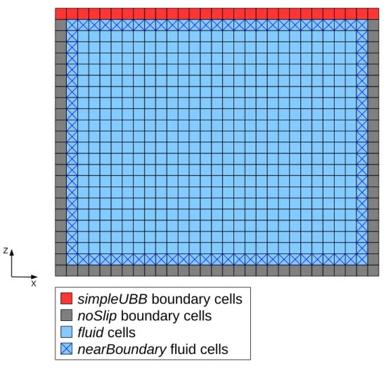
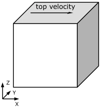
The 3D LDC problem consists of a steady fluid in a cubic cavity, where all boundaries are stationary except for the upper boundary, where a constant velocity is imposed inx direction, as depicted in Figure 2.3.
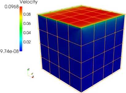
When running an LDC simulation, as more time steps are executed, the top velocity creates a flow towards the east (right-hand) boundary, then fluid starts to flow towards the bottom boundary and so on. After a large amount of time steps, eventually a central vortex can be identified in the cavity as depicted in Figure 2.4.
Figure 2.3: Representation of the 3D LDC problem.
Figure 2.4: Resulting velocity in theymidplane of a LDC simulation.
2.4
waLBerla Framework
waLBerla (Widely Applicable Lattice Boltzmann from Erlangen) is a massively parallel software framework created and maintained by the Department of System Simulation of the Friedrich-Alexander-Universität Erlangen-Nürnberg [5]. It supports a wide range of physical phenomena [7] and runs on some of the top 10 HPC clusters in the world [11].
The waLBerla framework has already been refactored two times during its development. A previous refactoring of the framework, developed in 2012, was specialized in GPU clusters [13], however it is not being maintained anymore because its architecture did not suit the
requirements for the new features planned for the framework. This work is based on the active architectural refactoring of the framework, which referred in this text for simplicity as the base version.
waLBerla is mainly centered around the LBM, but its applicability is not limited to this family of algorithms [8]. Although it provides classes to help implementing algorithms based on LBM, its design is sufficiently generic to make it suitable for implementing a variety of stencil based applications. In order to split the simulation computation among the cluster nodes, it employs a block partitioning of the simulation domain.
The framework is programmed in C++11 and implements algorithms that take advan-tage of HPC clusters and hardware specific features. It makes extensive use of C++templates in order to handle user defined data types while keeping an optimal performance.
2.4.1
Application Structure
As a framework, waLBerla is designed so that users, i.e. application programmers, can develop applications by extending the framework’s basic functionalities. HPC applications developed using waLBerla are usually structured as following (detailed information about the mentioned classes can be found in Section 2.4.2):
1. Creation and initialization: The domain data structure is created and initialized. Typi-cally, the domain is decomposed into axis-aligned blocks represented by theIBlockclass. Blocks themselves are containers for fields, the actual simulation data. Fields can be represented by an user defined data structure or by classes provided by the framework, such asField,GhostLayerFieldorGPUField.
2. Operation definition: The user is responsible to define a sequence of operations that will be executed on the domain data in every step of the simulation. The user can implement some of the operations, but the framework already provides a set of convenient operations that the user can also select. In a typical application, the operations are classified as following:
• Communication: Communicate data between neighboring blocks. Communication can occur locally, i.e. in the same process, or remotely, i.e. between different process, although most of the complexity involving different types of communication are transparent to the user. Remote communication usually involves MPI. A set of communication schemes with varied purposes is provided by the framework, such as
UniformDirectSchemeandGhostLayerFieldcopy.
• Boundary handling: Operate on lattice cells at the domain boundary. The frame-work provides some common boundary handling operations for LBM, such asno slipandfree slip.
• Sweep: Operate on lattice cells other than boundary cells. It is typically implemented by the user via a functor class referred in this work asBlockSweep.
3. Simulation loop: Execute the defined operations in a loop for a given number of steps, i.e. iterations. The infrastructure behind the simulation loop is provided by the framework and manages the sequence of operations among all simulation processes. The framework is capable of allocating blocks on multiple processes that can be placed on multiple nodes. A process can run one or more blocks, but a block is always completely processed by a single process.
Listing 2.1 shows the structure of a very simple example of an application using waLBerla:
Listing 2.1: Structure of a simple application using waLBerla.
1 // Creation and initialization
2 shared_ptr<StructuredBlockForest> blocks = createUniformBlockGrid (
3 2, 2, 2, // number of blocks in x, y, z directions
4 200, 200, 200, // number of cells per block in x, y, z directions
5 1, // length of one cell in physical coordinates
6 true, // run each block in a separate process
7 false, false, false); // domain periodicy in x, y, z directions
8 BlockDataID fieldId = blocks->addStructuredBlockData<
9 GhostLayerField<double, 19> >(createGhostLayerField, "Field"); 10
11 // Operation definition
12 SweepTimeloop timeloop(blocks, numberOfTimesteps);
13 UniformBufferedScheme<stencil::D3Q19> communicationScheme(blocks); 14 timeloop.add() << BeforeFunction(communicationScheme, "Communication") 15 << Sweep(BoundaryHandling(fieldId), "BoundaryHandling");
16 timeloop.add() << Sweep(BlockSweep(fieldId), "Sweep"); 17
18 // Simulation loop
19 timeloop.run();
2.4.2
Framework Architecture
This section presents the architecture of the base version of waLBerla. The architecture is presented in a simplified way, focusing only in aspects that are relevant for the understanding of the proposed solutions.
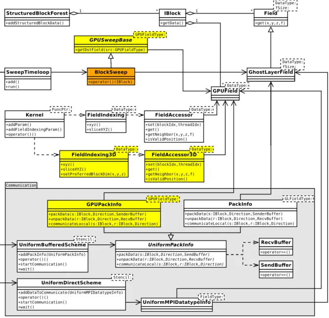
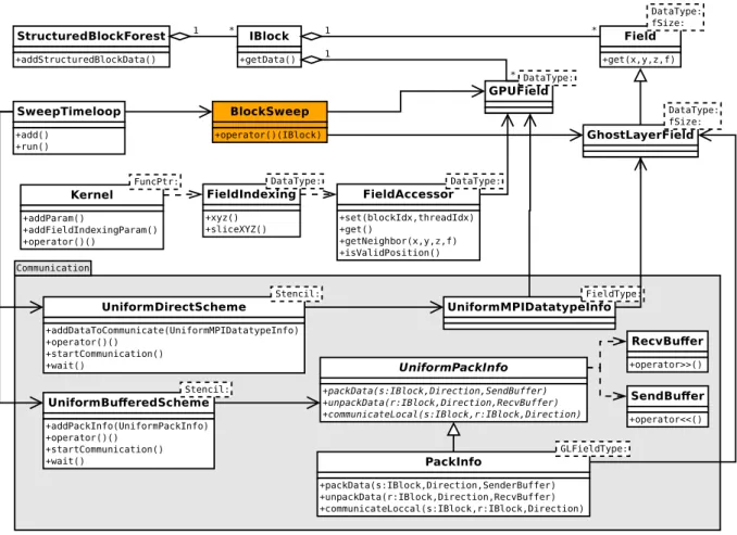
The waLBerla framework provides a set of classes and functions for coding HPC applications. In order to handle user defined data types while keeping a good performance, many of the framework classes are template classes. The class diagram depicting the main classes that are required to implement stencil based applications as well as their relationship are shown in Figure 2.5.
A description of each class depicted in Figure 2.5 is following:
• IBlock: This class represents an axis-aligned rectangular decomposition of the domain and manages all data that lies in that partition. It is a container for the actual simulation data. Each block can be attributed to a different processing unit through schemes provided by the framework, e.g. UniformBufferedScheme.
– getData(): Retrieve simulation data stored in theIBlock, usually aFieldor its derived classes, aGPUField, or a user defined type.
• StructuredBlockForest: This class manages a structured set ofIBlocks resulted from a domain decomposition. It is a facade that provides a simplified interface to a complex system of classes that actually stores theIBlocks.
– addStructuredBlockData(): Initialize data of everyIBlock managed by the class. • Field: This is the base class for storing lattices in CPU main memory. The stored lattice
data corresponds to a single block of a decomposed domain. It is structured as a four-dimensional grid with (x,y,z, f) coordinates, where the first three dimensions correspond
Figure 2.5: Class diagram for an application using the base version of waLBerla. Some interme-diary classes and methods are omitted for simplicity. The classBlockSweepin orange is defined by the user. All remaining classes are part of the waLBerla framework. Classes directly involved in communication are grouped into theCommunicationpackage.
to 3D space and the fourth dimension is used for indexing within a cell. In LBM, the fourth dimension is usually used for indexing the particle distribution functions (PDFs). It is implemented as vector with cells arranged contiguously in memory by default, or padded for memory alignment. As depicted in Figure 2.6, two different memory layouts are supported:fzyxandzyxf. TheDataTypetemplate parameter represents the data type stored by the class. ThefSizetemplate parameter is the size of thef coordinate.
– get(x, y z, f): Return a reference to a lattice cell value given its coordinates.
• GhostLayerField: This class extendsFieldwith a ghost layer. A ghost layer is a layer of additional cells around the lattice cells. The ghost layer cells store locally the cell values from the neighboring lattices that a stencil requires. The framework updates the value of the ghost layer cells at every time step, which requires communication. The template parameters follow those of its base class.
• GPUField: This class is a field for storing lattices in GPU memory. LikeField and its derived classes, it is also structured as a four-dimensional grid with (x,y,z,f) coordinates. It is implemented as a 3D vector in GPU memory and only supports padded memory, which is allocated and automatically aligned bycudaMalloc3D(). This kind of padded
Figure 2.6: fzyx and zyxf memory layouts that are supported by field classes such as Field,
GhostLayerField andGPUField [4]. The relative position of the dimensions in memory are specified in the layout names, where reading from left to right are specified the outmost to the innermost position in memory. That is, in thefzyxlayout, f is the outmost andx the innermost, and in thezyxf layout, z is the outmost and f the innermost. As a consequence, contiguous elements are inxdimension forfzyxlayout and in f dimension forzyxf layout.
memory is often referred as pitched memory [24]. Like GhostLayerField, it contains a ghost layer for storing locally cell values from the neighboring blocks. Both memory layoutsfzyxandzyxf are supported. TheDataTypetemplate parameter represents the data type stored by the class.
• Kernel: This is a CUDA kernel wrapper that is required to launch kernels from code not compiled with nvcc(NVIDIA CUDA Compiler). The wrapper is required because waLBerla makes use of many C++11 features that were not properly supported bynvcc
when the GPU support was introduced in the framework. TheFuncPtrtemplate parameter is the type of the kernel function to be called.
– addParam(): Add parameter to the kernel.
– addFieldIndexingParam(): Add an indexedGPUFieldparameter to the kernel, where indexing is made by theFieldIndexingclass.
– operator()(): Call the CUDA kernel.
• FieldIndexing: This class conveniently maps (x,y,z, f) coordinates of a GPUField to CUDA’s block and thread coordinates. Mapping depends on which memory layout is set on
GPUField. Forfzyxmemory layout, mapping is done so that theGPUField’s coordinates
x,y,zand f are mapped to CUDA’s coordinatesthreadIdx.x,blockIdx.x,blockIdx.yand
blockIdx.z, respectively. Forzyxf memory layout, on the other hand, mapping is done so that the GPUField’s coordinates x, y, z and f are mapped to CUDA’s coordinates
blockIdx.x,blockIdx.y,blockIdx.zandthreadIdx.x, respectively. The mapping created by this class is kept by theFieldAccessorclass, which allows for accessing theGPUFielddata from inside a CUDA kernel. TheDataTypetemplate parameter follows the one specified onGPUField.
– xyz(): Create a mapping for all cells of a GPUField, so that a CUDA thread is allocated for eachGPUField’s cell.
– sliceXYZ(): Create a mapping for cells lying within a given slice of aGPUField, so that a CUDA thread is allocated for eachGPUField’s cell within the slice.
• FieldAccessor: This class allows CUDA kernels to access data fromGPUFieldinstances. Access is made so that everyGPUFieldelement is conveniently mapped to a CUDA thread as defined byFieldIndexing. TheDataTypetemplate parameter follows the one specified onGPUField.
– set(blockIdx, threadIdx): Set up the mapping of coordinates given the CUDA indexes
blockIdxand threadIdx. It must be called before any other method call inside the kernel.
– get(): Return theGPUField’s element mapped to the current kernel.
– getNeighbor(x,y,z,f): Return theGPUField’s element placed on the (x,y,z,f) relative coordinates to the element mapped to the current kernel.
– isValidPosition(): Verify whether or not the element mapped to the current kernel is inside theGPUField’s domain limits.
• BlockSweep: This is not a class provided by waLBerla but a functor class that the user must implement in order to operate on everyIBlock. The framework is responsible for traversing everyIBlockinstance managed by theStructuredBlockForestand pass its pointer to theBlockSweep::operator()(). The user can choose any name for this class.
– operator()(IBlock): This operator is called by the framework, receiving anIBlock
pointer as argument. The programmer must code in this operator the routines to oper-ate on theIBlock’s data, which is usually a lattice type such asField,GhostLayerField
orGPUField.
• SweepTimeloop: This class manages the execution of the time steps. It allows the addition of functions or functors to be called at every time step during the simulation execution. Therefore, in order to make the framework execute the operations coded in
BlockSweep::operator()(), the user must register aBlockSweepinstance into a SweepTi-meloopinstance.
– add(): Register functions or functors to be executed at every time step.
– run(): Start the execution of a simulation.
• UniformPackInfo: This is a communication abstract class that encapsulates key opera-tions used in the communication betweenIBlocks. For communication between blocks owned by different processes, i.e. for remote communication, it encapsulates pack and unpack operations. For communication between blocks owned by the same process, i.e. for local communication, it encapsulates a local copy operation. Those operations must be implemented by a concrete derived class for performing data transfer between specific types of field. Implementations should proceed so that the proper data segments of a field are sent to the ghost layers of the neighboring blocks.
– packData(sender:IBlock, Direction, SendBuffer): This is the abstract method for packing data from thesenderblock into theSendBufferfor communication with the neighboring block towards the given stencilDirection.
– unpackData(receiver:IBlock, Direction, RecvBuffer): This is the abstract method for unpacking data from theRecvBufferinto the ghost layer of thereceiverblock, where data was sent by the neighboring block towards the given stencilDirection.
– communicateLocal(sender:IBlock, receiver:IBlock, Direction): This is the abstract method for local communication, where data from thesenderblock is copied into the ghost layer of thereceiverneighboring block that lies in the given stencilDirection. • PackInfo: This is a concrete specialization ofUniformPackInfothat implements pack-Data(),unpackData()andcommunicateLocal()operations for communication between
GhostLayerFields, i.e. between fields stored in the main CPU memory. TheGLFieldType
template parameter is a fully qualifiedGhostLayerFieldtype, i.e. aGhostLayerFieldwith all its template parameters defined.
• UniformBufferedScheme: This is a communication scheme for a domain decomposed into uniform blocks, i.e. axis-aligned blocks with the same dimensions. It updates the ghost layers of all fields in the domain with information from the neighboring blocks through synchronous or asynchronous communication. TheStenciltemplate parameter defines the communication neighboring topology.
– addPackInfo(UniformPackInfo): Register a UniformPackInfo. Regarding the pre-sented class hierarchy, the concreteUniformPackInfomust be aPackInfo.
– operator()(): Communicate synchronously.
– startCommunication(): Start an asynchronous communication.
– wait(): Wait an asynchronous communication completion.
• SendBuffer: This is a convenient representation of a buffer for outgoing MPI messages.
– operator<<(): Add a data value to the buffer. Calls to this operator can be chained for convenience.
• RecvBuffer: This is a convenient representation of a buffer for incoming MPI messages.
– operator>>(): Extract a data value from the buffer. Calls to this operator can be chained for convenience.
• UniformDirectScheme: LikeUniformBufferedScheme, this is also a scheme for uniform block grid communication. However, it allows fields to communicate with the neighboring blocks directly via MPI data types rather than aUniformPackInfoclass. To this end, it makes use of CUDA-aware MPI technology. Synchronous and asynchronous communi-cation are supported. Fields of an arbitrary type are allowed as long as they have ghost layers for communication. TheStenciltemplate parameter defines the communication neighboring topology.
– addDataToCommunicate(UniformMPIDatatypeInfo): Register an MPI data type through aUniformMPIDatatypeInfo.
– operator()(): Communicate synchronously.
– startCommunication(): Start an asynchronous communication.
• UniformMPIDatatypeInfo: This class encapsulates the MPI data types from the field type given by theFieldTypetemplate parameter. Fields with ghost layer such as GhostLayer-FieldandGPUFieldare supported. The MPI data types of a field allow the decomposition blocks to communicate without the buffersSendBufferandRecvBuffer.
In the base version of waLBerla, there are basically two options for GPU communication:
UniformDirectSchemeandGhostLayerFieldcopy. Although both are functional, as discussed in Section 6.2.2, tests have shown that they have poor performance, which prevents the user from implementing efficient HPC applications using GPUs.
TheUniformDirectSchemecommunication can be set up by passing a fully qualified
GPUFieldtype to the template parameter of aUniformMPIDatatypeInfo, then adding it to an instance of theUniformDirectSchemeclass via theaddDataToCommunicate()method.
TheGhostLayerFieldcopy communication can be implemented by first setting up an ordinary CPU communication forGhostLayerFields, creatingGPUFields for processing data on GPU, then defining copy operations betweenGhostLayerFieldandGPUFieldto be performed at every step of the simulation, as shown in the sequence diagram in Figure 2.7. The required CPU communication can be set up by passing a fully qualifiedGhostLayerFieldtype to the template parameter of aPackInfo, then adding it to an instance of aUniformBufferedSchemeclass via the
addPackInfo()method.
Figure 2.7: Sequence diagram forGhostLayerFieldcopy communication. SweepTimeloopstarts communication on theUniformBufferedSchemeand waits for the communication completion. In
startCommunication(), data is exchanged between the neighboringGhostLayerFields. The Block-Sweep::operator()()is then called, copying the field data fromGhostLayerFieldtoGPUFieldvia thecuda::fieldCpy()function. Then, the CUDA kernel is executed by callingKernel::operator()()
in order to process field data on GPU. Finally, the resulting data is copied fromGPUFieldback to theGhostLayerField.
Literature Review
This chapter presents relevant literature for the research presented in this dissertation, including works focused on kernel optimization, GPU communication and HPC framework architecture.
3.1
Optimized Kernels
This section presents literature review of works focused on single block GPU simula-tions with optimized LBM kernels.
Habich et al. [13] presents an optimized D3Q19 LBM solver implemented for GPUs using both, CUDA and OpenCL. The presented optimizations and developed experiments are focused on single block LBM. The optimization techniques are focused on improving memory access since it was identified that the implemented algorithm is limited by memory bandwidth. The LDC problem was used for verifying the presented optimizations and reached about 152 MFLUPS (Million Fluid Lattice Updates per Second) on an NVIDIA Tesla C2070 with double precision, contiguous memory, domain size of 2003 cells and GPU’s ECC (Error-Correcting Code) enabled.
A single block LDC application implemented with CUDA using the base version of waLBerla is introduced by Sepka [42]. The presented CUDA kernel showed to be highly optimized, specially with contiguous memory and GPU’s ECC enabled. For a domain size of 2003cells, the LDC application reached 159 MLUPS (Million Lattice Updates per Second) on an NVIDIA Tesla C2075. For a domain size of 1283 cells, it performed 413 MLUPS on an NVIDIA Tesla K40m.
3.2
GPU Communication
This section presents literature review of works focused on GPU-to-GPU communica-tion.
A GPU-aware MPI design based on MVAPICH2 for simplifying programming on GPU clusters is introduced by Wang et al. [48]. The design can handle both contiguous and non-contiguous GPU data. As performance issues caused by non-contiguous data access were identified, the proposed design transforms MPI datatypes into vectors and uses CUDA kernels for packing and unpacking. The described approach also uses pipeline for overlapping GPU data pack/unpack operations, DMA data movement on PCIe and GPUDirect RDMA data transfers. The paper presents benchmarks with an optimized 3D LBM application on GPU clusters. On
the Oakley supercomputer, it was observed up to 19.9% improvement in application level performance for 64 GPUs.
Habich et al. [12] presents optimization strategies for an LBM solver with a D3Q19 stencil on NVIDIA GPUs, focusing on memory alignment and register shortage. It makes use of the STREAM benchmark [19] in order to demonstrate the GPU parallelization approach and obtain an upper limit for implementation performance. According to the paper, the optimized code is up to one order of magnitude faster than standard two-socket x86 servers with AMD Barcelona or Intel Nehalem CPUs. The potential benefits of multi-GPU parallelism in computer clusters is analyzed based on PCIe data transfer rates. The paper concludes that PCIe bus as well as the InfiniBand network have a substantial impact on performance since the communication can take as long as twice the computational time spent on the GPU. Consequently, the communication is the major limiting factor for the overall performance.
Shainer et al. [43] discusses issues involving the GPU-CPU-InfiniBand system archi-tecture, which usually requires the CPU to initiate and manage memory transfers between remote GPUs via a high-speed InfiniBand network. The paper introduces for the first time the GPUDirect RDMA technology, which enables the Tesla GPUs to transfer data via InfiniBand without the involvement of the CPU or buffer copies, hence reducing the GPU communication time and increasing overall system performance. Performance was tested running two distinct molecular dynamics simulation programs, Amber [3] and LAMMPS [34], in a cluster with 8 nodes, each with a single NVIDIA Fermi GPU and Mellanox ConnectX-2 InfiniBand adapter. It was demonstrated that GPUDirect RDMA can improve communication performance up to 33%.
Potluri et al. [36] verified that communication is a critical bottleneck in achieving the full potential of GPU-based supercomputers. Although MPI libraries such as MVAPICH2 have provided solutions to alleviate communication overhead by using techniques like pipelining, data in the GPU memory still has to be moved into the CPU memory before it can be sent over the network. This paper also presents the GPUDirect RDMA as a solution to eliminate this overhead. Besides evaluating the first version of GPUDirect RDMA for InfiniBand, the paper proposes enhancements in the MVAPICH2 MPI library to efficiently take advantage of it for inter-node GPU-GPU communication. The benchmark performed has shown that the proposed functionalities improved the inter-node GPU-GPU communication latency on usingMPI_Send
andMPI_Recvon a Sandy Bridge platform by 69% and 32% for 4-Byte and 128-KByte messages, respectively, in comparison with an out-of-the-box MVAPICH2. In addition, the enhancements boosted the unidirectional bandwidth achieved using 4-KByte and 64-KByte messages by 100% and 35%, respectively. The impact of the proposed enhancements was also demonstrated using two applications, GPULBM [40] and AWP-ODC [33], showing improvements in their communication time by up to 35% and 40%, respectively.
Different approaches for using multiple GPUs in the simulation of physical systems are presented and compared by Bernaschi, M. et al. [2]. The benchmarks adopted are 3D Heisenberg spin glass model and a solution of Poisson equation. The results showed that the GPUDirect P2P memory copy along with the CUDA-aware MPI features of libraries such as MVAPICH2 and Open MPI can hide the communication overhead in case computation time is long enough. The most valuable contribution of this paper is the fact that it is one of the few works that compares the CUDA-aware MPI performance of MVAPICH2 and Open MPI libraries. The paper demonstrates that MVAPICH2 can take better advantage of CUDA-aware MPI features than Open MPI. Besides, MVAPICH2 can achieve higher parallel efficiency compared to Open MPI. In a naive case involving only intra-node communication with 8 GPUs, MVAPICH2 achieved 76% of parallel efficiency while Open MPI achieved 65%. In a more complex scenario involving inter-node communication with 8 nodes, one GPU per node and overlap between communication
and computation, MVAPICH2 achieved 80% of parallel efficiency while Open MPI achieved 73%.
A method for minimizing the GPU communication time of stencil based applications with a non-blocking InfiniBand interconnection network is presented by Schneible et al. [41]. It is affirmed that although minimizing the surface of the lattice decompositions increases communi-cation performance by reducing message size, this approach is optimal only for naive cases where bandwidth is assumed to be equal between all GPUs and latency is assumed to be negligible. On more realistic systems, the intra-node communication between GPUs has greater bandwidth and lower latency than inter-node communication. As a consequence, the optimal solution to split the lattice is not obvious and depends upon the application and hardware parameters. The paper demonstrates that it is impractical to determine the optimal lattice decomposition through brute force method even for moderate sized applications. Thus, the method the paper proposes is focused on reducing communication time rather than communication size, demonstrating a significant performance increase over the minimal surface technique in certain cases. This method splits the performance model into two models: application model and communication model. The former is at a high level and takes into account the application parameters and node architecture. The second, on the other hand, is a GPU cluster communication model that takes into account the topology of the interconnections considering every combination of intra-node and inter-node communication with and without GPUDirect 1.0 and GPUDirect P2P. By improving overlapping of communication and computation, the proposed method was able to increase the performance of the most computationally intensive kernel of a lattice Quantum Chromodynamics (QCD) implementation by 25%. In addition, the paper concludes that while the optimal heterogeneous system design for stencil based applications has only a single GPU per node, this does not offer the best performance per dollar. Instead, the most cost efficient systems have two GPUs per node.
The use of multiple GPUs as well as heterogeneous processing and communication for parallel computation of an LBM solver using an early version of the waLBerla framework is addresses by Feichtinger [8]. It affirms that the waLBerla framework is able to attain good runtime performance on various platforms despite the inevitable overheads for flexibility. The paper shows that scalable multi-GPU implementation for HPC clusters can be achieved for LBM simulations. It states that the kernel performance can be sustained for weak scaling on InfiniBand clusters but using multiple GPUs in strong scaling scenarios is much less efficient than running CPU-only simulations on IBM BG/P and x86-based clusters. Optimizations in GPU memory access based on padding strategies to favor memory coalescence are suggested as a future work.
3.3
HPC Framework Architecture
This section presents literature review of works focused on architectural aspects of HPC software frameworks.
The architecture of the base version of waLBerla was presented by Godenschwager et al. [11]. waLBerla’s design was driven by a performance analysis of petascale supercomputers. The low-level parts of the framework make extensive use of template programming techniques for achieving high performance while maintaining flexibility. In high-level, the non-performance critical parts make use of polymorphism to ensure flexibility and usability. The paper also presents the framework support for domains with arbitrary shapes. Each block of the domain can be recursively decomposed into eight equally sized smaller blocks geometrically resulting in a forest of octrees. The domain initialization process is also described highlighting the advantages of some waLBerla features compared to other frameworks. Results of the framework
performance are presented for varied implementations of 3D LBM running on SuperMUC and JUQUEEN supercomputers, respectively the number 27 and number 13 on the Top500 list of June 2016 [45]. Resolutions with more than one trillion cells were reached with performance up to 1.93×10⁶MLUPS using 1.8 million threads. The simulation of a complex vascular geometry of the human coronary tree presented excellent weak and strong scaling performance. A record of a 1012fluid lattice cells was achieved in the largest weak scaling simulations. Although this paper is important to understand key design features of the current waLBerla framework, it does not discuss any feature related to GPU support.
Sepka [42] proposed relevant future works for the base version of waLBerla in order to improve its usability on GPU-enabled clusters, including: a GPU communication mechanism, a mechanism for improving memory usage efficiency, enhancements in LDC kernels for handling decomposed domains and generic boundary handling kernels for LBM simulations. A drawback of the dissertation is the proposed solution for contiguous GPU memory for waLBerla, which involves a massive code duplication.
GPU Engineering for an HPC Framework
The use of software frameworks is crucial to lower the development cost of efficient HPC applications as well as to increase the HPC adoption in various fields of science and engineering. Besides, the use of GPUs in HPC systems is a trend to lower costs while increasing processing power. Therefore, enhancing GPU performance and usability of a HPC framework such as waLBerla [6] is a valuable contribution.
Communication is a major performance bottleneck in harnessing the full potential of GPUs in HPC [35, 36]. Although the base version of waLBerla presents good performance on CPUs [11], preliminary tests have shown that its available GPU communication solutions perform poorly. Therefore, working to improve the GPU communication is an obvious choice to enhance the overall GPU performance for the framework. Besides, GPU communication is an important functionality that can be implemented in a generic way in the framework so that multiple applications can take advantage of it.
An efficient use of the GPU memory is also an important feature of an HPC framework as it allows using less cluster nodes for a given simulation or running simulations with larger domains. Thus, promoting a better usage of the GPU memory also contributes with waLBerla’s applicability.
This chapter presents solutions to improve waLBerla performance and memory effi -ciency, including a new communication infrastructure and its associated programing interface for waLBerla. This new infrastructure employs state-of-the-art technologies and strategies in order to provide efficient inter-node and intra-node GPU communication. Software engineering and advanced programming techniques are employed in order to keep usability while improving performance. In addition, an application implementing a lid-driven cavity simulation was devel-oped in order to verify the validation, performance and memory efficiency of the implemented solutions for the framework.
4.1
Architecture Overview
A major objective of the proposed architecture is allowing new functionalities and enhancements improve performance and memory efficiency while keeping usability and main-tainability. To this end, the best practices in software engineering were considered when implementing the new functionalities, such as encapsulation, code reuse and extensibility.
The new functionalities proposed for waLBerla required extending the framework with new classes. As depicted in the class diagram in Figure 4.1, for developing a new GPU communication mechanism, theGPUPackInfoclass was created, which is a new concrete class derived fromUniformPackInfo. The base classGPUSweepBasewas created allowing users to
deriveBlockSweeps from it in order to easily improve memory management. Finally, in order to make field indexing in CUDA kernels more flexible, a new pair of indexing classes,FieldIndex3D
andFieldAccessor3D, were also developed.
Figure 4.1: Class diagram for the new architecture for waLBerla. The new classes are highlighted in yellow. The classBlockSweepin orange is defined by the user. Some intermediary classes and methods are omitted for simplicity.
Details about the new classes developed for waLBerla can be found in the next sections of this chapter. GPUPackInfois described in Section 4.2. GPUSweepBaseis presented in Sec-tion 4.3.1. The pair of classesFieldIndex3DandFieldAccessor3Dare described in Section 4.3.3.
4.2
GPU Communication Engineering
Improving GPU communication performance for waLBerla has become a major objec-tive as the two GPU communication mechanisms available in base version of framework have shown poor performance in preliminary tests.
TheGhostLayerFieldcopy communication mechanism, as introduced in Section 2.4.2, needs to copy the whole domain data from CPU to GPU and vice versa on every simulation step. It was basically a temporary solution for allowing usingGPUFieldfor multi-node simulation while there was no specific solution for GPU communication at that time. Thus, it was never expected to be efficient.
TheUniformDirectSchemecommunication mechanism, on the other hand, despite using CUDA-aware MPI and GPUDirect features, surprisingly showed a even worse performance in many scenarios. Tests showed that the poor performance arises when the Open MPI needs to communicate non-contiguous data types directly from a pointer to the GPU memory.
This section presents the solution for improving GPU communication performance, including design and implementation details.
4.2.1
Base Communication Architecture
Among some possible solutions to improve GPU communication performance, it was chosen to create a new GPU communication mechanism for the framework that reuses much of the architecture that has been used by CPU communication. Most of the proposed communication mechanism is encapsulated in theGPUPackInfoclass and helper functions. Besides promoting performance improvements and code reuse, the new mechanism is also an important step for future work towards the development of heterogeneous computing involving GPU and CPU computing nodes.
For a better understanding of the proposed GPU communication mechanism, it is im-portant analyzing howUniformBufferedSchememanages communication and its relation with
UniformPackInfo,RecvBufferandSendBuffer. Algorithm 1 describes in a very simplified way how classes collaborate in the UniformBufferedScheme’s method startCommunication() for allowing communication between every block and its neighbors via the abstract class Uniform-PackInfo.
Algorithm 1UniformBufferedScheme::startCommunication()pseudocode.
1: uni f or mPack In f o:U ni f or mPack In f o
2: sendBu f f er: SendBu f f er
3: r ecvBu f f er: RecvBu f f er
4: for eachblock ∈I Blockdo
5: for eachdir ∈Stencildo
6: neighbor ←block.get N eighbor(dir) //get the neighboring block indirdirection
7: if blockandneighbor are owned by the same processthen
8: uni f or mPack In f o.communicateLocal(block,neighbor)
9: else
10: uni f or mPack In f o.pack Data(block,dir,sendBu f f er)
11: mpiSendAndReceive() //communicate via MPI
12: uni f or mPack In f o.unpack Data(block,dir,r ecvBu f f er)
13: end if
14: end for
15: end for
4.2.2
Communication Architecture Extension
In order to reuse the existing architecture, the proposed GPU communication solution consists of developing a concreteUniformPackInfoderived class,GPUPackInfo, for properly
packing/unpackingGPUFields data. Besides being compatible withUniformBufferedScheme,
GPUPackInfoalso allows for any other communication scheme that is compatible with Uniform-PackInfoto be promptly able to handle communication between GPU blocks.
As a concrete specialization of UniformPackInfo for communication data between
GPUField block,GPUFieldPackInfoimplements theUniformPackInfo’s abstract methods as following:
• packData(sender:IBlock, Direction, SendBuffer): Pack data from thesender GPUField
block into theSendBufferfor communication with the neighboringGPUFieldblock in the givenDirection. Packing is made throughcudaMemcpy3D().
• unpackData(receiver:IBlock, Direction, RecvBuffer): Unpack data from theRecvBuffer
into the ghost layer of thereceiver GPUFieldblock, where data was sent by the neighboring
GPUField block towards the given Direction. Unpacking is made through cudaMem-cpy3D().
• communicateLocal(sender:IBlock, receiver:IBlock, Direction): Copy data from thesender GPUField block into the ghost layer of thereceiver GPUField neighboring block that lies in the givenDirection. Copy is make through GPUDirect P2P memory transfer with
cudaMemcpy3D().
When coping data from aGPUFieldinto theSendBuffer, the field’s region that needs be by copied is a slice adjacent to the ghost layer in a given direction. The coordinates and dimensions of that slice are calculated using thegetSliceBeforeGhostLayer()function. Similarly, when coping data from theRecvBufferinto theGPUField’s ghost layer, the ghost layer region in the given direction is calculated using thegetGhostRegion()function.
SendBuffer and RecvBuffer are buffers in the CPU main memory for outgoing and incoming MPI messages. Both provide handy operators for helping data transfer. SendBuffer
providesoperator<<()for adding data to the buffer, whileRecvBufferprovidesoperator>>()for extracting data from the buffer. However, those buffer operators were prepared only to handle pointers to the CPU main memory. Thus, enhancements were required for the buffer classes so data transferring data from GPU memory to theSendBufferand from theRecvBufferto the GPU memory can be done efficiently.
The solution for SendBuffer comes by creating a method forward(uint_t elements), which makes the buffer skip the given number of elements so thatcudaMemcpy3D()can be used to transfer data from theGPUFieldto the gap created in the buffer.
Similarly, the solution forRecvBufferrequired changes in the existing methodskip(size_t elements)in order to skip the given number of elements in the buffer and return a pointer to the beginning of the skipped region. Thus,cudaMemcpy3D()can be used to transfer data from the skipped region in the buffer to theGPUField’s ghost layer.
4.2.3
Data Transfer Details
GPUField represents a 4D structure in device memory with (x,y,z, f) coordinates. However, CUDA Runtime API supports directly objects with up to 3D dimensions [25]. Thus, additional effort is required when handlingGPUField’s memory using CUDA Runtime API functions and data structures.
Regarding thefzyx memory layout, when allocating device memory with cudaMal-loc3D()from the CUDA Runtime API for storing theGPUField’s lattice, it is required a memory
mapping for fitting theGPUField’s 4D structure into the allocated 3D memory object. It was done so thatGPUField’sx and ydimensions are directly mapped into the memory object’s x
and y dimension, butGPUField’s z and f dimensions are allocated as a 2D structure in the memory object’szdimension, withGPUField’s zplaced as the innermost dimension and f as the outmost dimension.
InUniformPackInfo, when data is transferred between aGPUFieldand one of the buffer classes, or between twoGPUField’s, thecudaMemcpy3D()function from the CUDA Runtime API is employed. cudaMemcpy3D()is capable of copying any axis-aligned 3D region from a 3D memory object into another 3D memory object, where any of the memory objects can be placed on either device or host memory. Again, the 4DGPUField’s structure and its mapping to 3D memory object have to be taken into consideration and additional steps are required in order to copy a 3D region of aGPUFieldinto theSendBuffer, copy theRecvBufferinto a 3D region of aGPUFieldor copy a 3D region of aGPUFieldinto a 3D region of anotherGPUField. As long as theGPUField’s f dimension is mapped in device memory as the outmost dimension for
fzyxmemory layout, a copy of a 3D region of aGPUFieldis made slice by slice in f dimension usingcudaMemcpy3D(). Thus, for the D3Q19 stencil, 19cudaMemcpy3D()calls are required for a single 3D region copy.
4.3
GPU Memory Engineering
This section presents the developed solutions for waLBerla that enhances the GPU memory support in different aspects. The developedGPUSweepBasebase class forBlockSweep
provides a simpleGPUFieldmanagement for sweeps and improves memory usage efficiency. The support for contiguous memory developed forGPUFieldshowed to have improved performance in many scenarios. Finally, the developed pair of classesFieldIndex3D andFieldAccessor3D
provide a flexible way to indexGPUFields in device memory.
4.3.1
Field Memory Management
In LBM and other stencil-based application, when a simulation step is calculated for a domain, the resulting data is usually stored in another domain. The former is referred as the source domain and the latter as the destination domain. The destination domain role is temporarily holding the calculations of a simulation step. Thus, in order to prepare of the next simulation step, source and destination domain pointers are swapped so that the source domain holds up-to-date data while the destination domain is ready for receiving the next step calculations.
As the calculation of a simulation step requires a source and a destination domain, it typically uses two times the amount of memory as required to store domain’s data. However, by taking advantage of domain block decomposition, it is possible to use for the destination domain only a fraction of the amount of memory required by the source domain. A requirement for making it possible is allocating many blocks per process rather than a single block per process. To this end, waLBerla supports decomposing domains so that each process can own a group of blocks.
The proposed solution for promoting a better memory management takes into consider-ation that the blocks within the same process are calculated sequentially by aBlockSweepclass. For uniform block decomposition where all blocks have the same size, instead of allocating a full sized domain as the destination domain, a single field with the dimension of a single source block plays the role of destination domain. Then, as soon as a simulation step is calculated
for a given source block, the pointers to source and destination fields are swapped so that the destination field is ready for holding the calculations of the next source block within the process. This is done until all source blocks owned by the process are calculated before proceeding to the next simulation step.
The presented memory management solution for the destination domain was encapsu-lated into theGPUSweepBaseclass as part of waLBerla. As depicted in Figure 4.1, a framework’s user can derive aBlockSweepclass from it in order to easily take advantage of its functionality.
GPUSweepBase is also a template class whose template parameter GPUFieldTypemakes it flexible in terms of the specificGPUFieldtype.
Provided that the user derivesBlockSweepfromGPUSweepBase, whenever the frame-work callsBlockSweep::operator(IBlock)in order to calculate a simulation step for the given block, all user’s code has to do for getting the destination field is callinggetDstField(src)passing the field of the source block as a parameter. By doing so, the application is ready to make a more efficient use of the device memory. Note that for a domain decomposed into Buniform blocks, the memory effectively used for the destination domain is1/Bof the memory required for the source domain.
In order to make the solution more generic in terms of domain decomposition, it was developed taking non-uniform block decomposition into consideration as well, where blocks can differ in sizes. To this end, GPUSweepBasekeeps a collection of destination fields with unique dimensions. Whenever a source field is passed as a parameter to getDstField(src), it is checked whether or not the destination field collection already owns a field with the same dimensions assrc. In case it does, the field is returned. Otherwise, a new destination field with same dimensions assrcis created, inserted into the collection and returned.
4.3.2
Contiguous Memory Support
Only pitched memory is supported by GPUField in the base version of waLBerla. However, some factors leaded to the decision of implementing support for contiguous memory as well: performance, memory usage and flexibility.
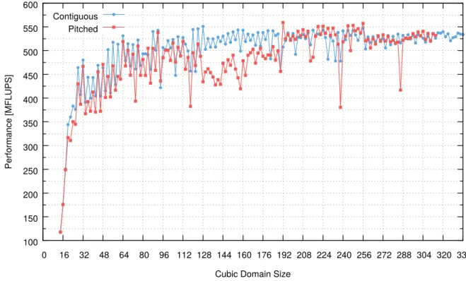
Frequently, pitched memory is recommended for allocations of data structures with two or more dimensions since it ensures that the allocation is properly padded to meet the alignment requirements for fast memory access [24]. Nonetheless, preliminary tests have shown that contiguous memory performs better than pitched memory in many scenarios, as can be observed in Figure 4.2. Besides, tests performed by Sepka [42] have also shown better performance for contiguous memory than pitched memory. Even though Habich et al. [13] has indeed shown better performance for pitched memory, that paper actually proposes a handcrafted pitched memory implementation for 128-byte alignment, which differs greatly from the 512-byte alignment thatcudaMalloc3D()allocates forGPUField. Supporting a configurable handcrafted memory alignment forGPUFieldis proposed as a future work.
In addition, contiguous memory has no padding while pitched memory has paddings in the innermost dimension when it does not meet the memory alignment constraint. Depending on how many bytes that the innermost dimension size in bytes is apart from the multiple of 512 that can fit it, pitched memory paddings can occupy a large amount of the memory, which makes contiguous memory more efficient in terms of memory usage.
In order to improve the memory usage efficiency and simulation performance when using pitched memory, the domain sizes are often adjusted to better fit the memory alignment. However, provided that domain sizes meet the memory alignment constraint, contiguous memory has shown to perform as good as pitched memory.
100 150 200 250 300 350 400 450 500 550 600 0 16 32 48 64 80 96 112 128 144 160 176 192 208 224 240 256 272 288 304 320 336 Performa nce [MFLUPS ]
Cubic Domain Size Contiguous
Pitched
Figure 4.2: Preliminary performance comparison between contiguous and pitched memory. The test consist of running 200 iterations of the lid-driven cavity kernels, introduced in Section 4.4.1, in a GPU of thecluster-ibsystem, described in Section 5.1, for domain sizes varying from 143to 3363cells. In order to mitigate warm-up interference in performance verification, every scenario is repeated 10 times and only the best performance is regarded. Note that, even though the best case occurred using pitched memory with domain size of 1923cells, contiguous memory performed better for most domain sizes. In addition, contiguous memory allowed simulating larger domains in the same GPU due to its better memory usage efficiency.
Sepka has proposed a contiguous memory solution forGPUFieldthat involves a massive code duplication: classes such asGPUField,FieldIndexingandFieldAccessoras well as stand-alone functions such asfieldCpywere duplicated into pitched and contiguous counterparts. The main drawbacks of that solution i
![Figure 2.1: Grid of thread blocks [24].](https://thumb-us.123doks.com/thumbv2/123dok_us/504070.2559476/17.892.262.583.131.545/figure-grid-of-thread-blocks.webp)
![Figure 2.2: The D3Q19 lattice model [31].](https://thumb-us.123doks.com/thumbv2/123dok_us/504070.2559476/19.892.182.661.119.499/figure-the-d-q-lattice-model.webp)
![Figure 2.6: fzyx and zyxf memory layouts that are supported by field classes such as Field, GhostLayerField and GPUField [4]](https://thumb-us.123doks.com/thumbv2/123dok_us/504070.2559476/24.892.135.805.134.416/figure-memory-layouts-supported-classes-field-ghostlayerfield-gpufield.webp)