INTRODUCTION Chapters 1. Operation 2. Theory of Operation 3. Specifications 4. Repair Information 5. Schematics 6. Parts 7. Calibration 8. Preventive Maintenance
A complete, detailed table of contents begins on page iii. Also, on the first page of each chapter a table of contents for that chapter is provided.
FOREWORD
This Service Manual (P/N 0070-00-0429) is intended as a guide, for technically qualified personnel, to use during repair and calibration procedures for the Accutorr Plus (part number 0998-00-0444-XX).NOTE:See the serial number label on the rear panel of the unit for part number identification. This manual also includes information on the Recorder and Predictive Temperature Modules.
The information in this manual has been divided into the eight chapters listed above. This publication may have been updated to reflect product design changes and/or manual improvements. Any such changes to this manual would be accomplished by supplying replacement pages and instructions for inserting or affixing them into the manual.
NOTE
Unauthorized servicing may void the remainder of the warranty. Check with the factory or with a local authorized Datascope representative to determine the warranty status of a particular instrument.
NOTE:This product is year 2000 compliant.
Copyright © Datascope Corp., 1999. Printed in U.S.A. All rights reserved. Contents of this publication may not be reproduced in any form without permission of Datascope Corp.
Accutorr Plus, Service Manual i
Chapter 1 - Operation
VAULT COPY
This page intentionally left blank.
ii Accutorr Plus, Service Manual
INTRODUCTION . . . i 1.0 OPERATION . . . 1-1
1.1 Introduction. . . 1-1 1.2 Controls and Indicators. . . 1-3 1.2.1 Front Panel. . . 1-4 1.2.2 Rear Panel . . . 1-13 1.2.3 Predictive Thermometer Module . . . 1-14 1.2.4 Recorder Module . . . 1-15 1.3 Operation. . . 1-17 1.3.1 Setting-Up / Turning Power On . . . 1-17 1.3.2 Patient Setup and Room/Bed Assignment. . . 1-18 1.3.2.1 Selecting the Patient Size . . . 1-18 1.3.2.2 Cuff Inflation Pressure . . . 1-18 1.3.2.3 Room Number and Bed Letter . . . 1-19 1.3.3 Manual NIBP Measurements and General NIBP
Measurement Information. . . 1-20 1.3.3.1 NIBP Pressure Limit Fail Safe. . . 1-22 1.3.3.2 Cuff Inflation Time. . . 1-22 1.3.3.3 Automatic Adjustment of Cuff Inflation Pressure
(Adaptive Inflation) . . . 1-22 1.3.4 Automatic NIBP Measurements (Interval Mode) . . . 1-23 1.3.4.1 Canceling an Automatic NIBP Measurement . . . 1-23 1.3.4.2 Changing the Interval setting . . . 1-24 1.3.4.3 Effects of Changing the Room Number and /or Bed
Letter on the Interval Setting . . . 1-24 1.3.4.4 Start and Deflate Functions. . . 1-24 1.3.5 Alarms . . . 1-25 1.3.5.1 Setting Alarm Limits . . . 1-25 1.3.5.2 Alarm Violations . . . 1-26 1.3.5.3 How to Mute Alarms . . . 1-27 1.3.5.4 Alarms and Changing the Room Number and/or
Bed Letter. . . 1-27 1.3.6 To View and Delete Stored Data (Trend Mode). . . 1-28 1.3.6.1 To View the Stored Measurements on the Accutorr
Plus NIBP . . . 1-28 1.3.6.2 To View the Stored Measurements on the Accutorr
Plus NIBP with Trend Screen and the Accutorr Plus
NIBP with Trend Screen and SpO2. . . 1-29
Accutorr Plus Service Manual iii
Introduction
1.3.6.3 To Delete the Stored Measurements on all
Models of the Accutorr Plus . . . 1-29 1.3.7 Setting the Alarm Volume and Beep Volume . . . 1-30 1.3.8 Setting the LCD Contrast (View Angle Adjustment) . . 1-31 1.3.9 Display Time Out Mode. . . 1-32 1.3.10 SpO2Measurements (Accutorr Plus model with SpO2) . 1-33 1.3.10.1 Datascope Pulse Oximetry Sensors . . . 1-33 1.3.10.2 Sequence for Establishing SpO2with Nellcor® Pulse
Oximetry* . . . 1-37 1.3.10.3 Sequence for Establishing SpO2with MasimoÒ Pulse
Oximetry* . . . 1-40 1.3.11 Temperature Measurement (optional) . . . 1-43 1.3.11.1 Predictive Thermometer Measurements . . . 1-43 1.3.11.2 How to Apply Probe Cover (PTM) . . . 1-43 1.3.11.3 How to Take Oral, Rectal, and Axillary Temperatures . 1-44 1.3.11.4 Storing Temperature Measurements . . . 1-45 1.3.12 Recorder (optional) . . . 1-46 1.3.13 How to Set the Clock (Date and Time) . . . 1-47 1.3.14 Battery Operation . . . 1-48 1.3.15 User Configuration . . . 1-49 1.3.16 Status and Error Codes . . . 1-51 1.3.17 How to Attach Optional Thermometer and
Recorder Modules. . . 1-52 1.3.18 Placement of the Quick Reference Card . . . 1-53 1.3.19 Placement of Recorder Paper Loading Label . . . 1-54
2.0 THEORY OF OPERATION . . . 2-1
2.1 Block Diagrams . . . 2-1 2.2 Detailed Circuit Descriptions . . . 2-2 2.2.1 LED/CPU Module, 0670-00-0650-03, -04. . . 2-9 2.2.1.1 Hardware Overview . . . 2-9 2.2.1.2 Software Overview . . . 2-9 2.2.1.3 Detailed Hardware Description. . . 2-10 2.2.2 NIBP Module, Linear Bleed . . . 2-17 2.2.3 Recorder Module . . . 2-20 2.2.4 Predictive Thermometer Module . . . 2-21 2.2.5 SpO2Module (Accutorr Plus with SpO2only) . . . 2-22 2.2.6 Main Power Supply. . . 2-25 2.2.7 Communication Board . . . 2-26 2.2.8 LCD Inverter Module - 0670-00-0649 . . . 2-28 2.2.9 Nellcor®MP 304 SpO2Circuit Board
Theory of Operation . . . 2-29 2.2.10 Interface NellcorÒ Board Theory of Operation . . . 2-30
iv Accutorr Plus Service Manual
Introduction Revised 12/20/00
2.2.11 Masimo SETÒ Technology. . . 2-31 2.2.12 Masimo Interface Board Theory of Operation . . . 2-32
3.0 SPECIFICATIONS . . . 3-1 3.1. Performance Specifications . . . 3-1 3.2 Safety Characteristics . . . 3-6 3.3 Physical Characteristics . . . 3-7 3.4 Environmental Characteristics . . . 3-7 3.5 Electrical Ratings . . . 3-7 3.6 Agency Compliance . . . 3-8 3.7 Electromagnetic Compatibility. . . 3-8 4.0 REPAIR INFORMATION . . . 4-1 4.1 Introduction. . . 4-1 4.2 Safety Precautions. . . 4-2 4.3 General Troubleshooting Guidelines . . . 4-2 4.4 Test Equipment Required . . . 4-3 4.5 Troubleshooting (Problem Isolation) . . . 4-4 4.5.1 Isolating the Problem, System Level . . . 4-5 4.5.2 Isolating the Problem within the Main Unit. . . 4-5 4.5.3 Isolating the Problem with Optional Accessory Modules. . . 4-6 4.5.4 Clinical Issues. . . 4-6 4.6 Disassembly Instructions . . . 4-9 4.6.1 Removal of the Rear Housing (27) . . . 4-9 4.6.2 Removal of the Front Bezel (2) . . . 4-9 4.6.3 Removal of the Keyboard Assembly (4). . . 4-9 4.6.4 Removal of the CPU Board Assembly (8) . . . 4-10 4.6.5 Removal of the NIBP Circuit Assembly (30) . . . 4-10 4.6.6 Removal of the Power Supply Assembly (41) . . . 4-10 4.6.7 Removal of the Motor Filter and LCD
High Voltage Assembly (35) . . . 4-11 4.6.8 Removal of the NIBP Air Pump Assembly (37) . . . 4-11 4.6.9 Removal of the LCD Display Assembly and Back Light (5) 4-11 4.6.10 Removal of the SpO2Circuit Board (40). . . 4-11 4.6.11 Removal and Replacement of the Internal Sealed
Lead Acid or Li-Ion Battery . . . 4-12 4.6.12 Removal of the AC Input Receptacle Assembly (16) . . . 4-12 4.6.13 Thermal Printer (Optional Module) . . . 4-12 4.6.14 Thermometer, Predictive (Optional Module) . . . 4-13 4.6.15 AccuTemp IR, Infrared Thermometer (optional
module) . . . 4-13 4.6.16 AccuTemp IR Mounting Cradle . . . 4-13
Accutorr Plus Service Manual v
4.6.17 Communication Board (45). . . 4-13
5.0 ASSEMBLY AND SCHEMATIC DIAGRAMS . . . 5-1 6.0 REPLACEMENT PARTS . . . 6-1
6.1 Introduction . . . 6-1 6.2 Available Replacement Parts and Sub-Assemblies . . . 6-1 6.3 Product Variations and Options . . . 6-1 6.4 Exchange Program . . . 6-1 6.5 Replacement Parts Pricing Information . . . 6-2 6.6 Ordering Information. . . 6-2 6.7 Abbreviations . . . 6-3 6.8 Isometric Drawings and Parts List . . . 6-5 6.8.1 Accutorr Plus Isometric Parts List (All Models) . . . 6-5 6.8.2 Recorder Module Isometric Parts List . . . 6-13 6.8.3 Predictive Temperature Module Isometric Parts List. . . 6-15 6.8.4 Mobile Stand Type 1 (Gray Base) Assembly Parts List . 6-17 6.8.5 Mobile Stand Type 2 (Black Base) Assembly Parts List . 6-19 6.8.6 Mounting Options . . . 6-19 6.9 Circuit Board Parts Lists. . . 6-21
7.0 CALIBRATION. . . 7-1
7.1 Introduction . . . 7-3 7.2 Warnings and Guidelines . . . 7-3 7.3 Test Equipment and Special Tools Required. . . 7-3 7.4 Power-Up Sequence, Internal Testing. . . 7-4 7.5 Service Diagnostics. . . 7-4 7.5.1 Introduction (Hidden Key) . . . 7-4 7.5.2 Software Version Test (0a, 0b). . . 7-5 7.5.3 Keypad Test . . . 7-6 7.5.4 LED Test (2a, 2b) . . . 7-7 7.5.5 Communications Test (3a, 3b) . . . 7-7 7.5.6 Recorder Test (4) . . . 7-7 7.5.6.1 Recorder Print Head Adjustment . . . 7-8 7.5.7 Pump Test (5). . . 7-8 7.5.8 Leak Test (7) . . . 7-9 7.5.9 Over Pressure Test (8a, 8b, 8c) . . . 7-9 7.5.10 Pulse Channel DC Offset Test (9a, 9b, 9c) . . . 7-10 7.5.11 Pulse Channel Average Noise Test (10a, 10b, 10c) . . . . 7-10 7.5.12 Main Pressure Transducer Verification Test
(11a, 11b, 11c) . . . 7-11
vi Accutorr Plus Service Manual
Introduction Revised 9/20/07
7.5.13 Verification of Accutorr Plus Pneumatic Performance, Using the “Cufflink” NIBP Emulator (11d) . . . 7-11 7.5.14 Over Pressure Transducer Verification (12c, 12a, 12b) . 7-12 7.5.15 Main Pressure Transducer Calibration. . . 7-12 7.5.16 Over Pressure Transducer Calibration . . . 7-13 7.5.17 Battery Selection (13) . . . 7-13 7.6 Predictive Thermometer Verification and Calibration. . . 7-14
7.6.1 Temperature Accuracy Verification with the
Predictive Temperature Simulator . . . 7-14 7.6.2 Water Bath Method . . . 7-15 7.6.3 System Calibration Procedure . . . 7-15 7.6.4 Temperature Verification Test, Infrared
Thermometer . . . 7-16 7.6.5 Low Battery Sensing . . . 7-17 7.7 Battery Test for Accutorr Plus . . . 7-18 7.7.1 Low Battery Indicator and Low Battery Cut-Off . . . 7-18 7.7.2 Set the Current Time . . . 7-19 7.8 NIBP Normal Operation . . . 7-20 7.9 Trend Memory Initialization . . . 7-21 7.10 SpO2Normal Operation (Accutorr Plus with SpO2only) . . . 7-21
8.0 PREVENTIVE MAINTENANCE . . . 8-1
8.1 Introduction . . . 8-1 8.2 Limitations of Physiological Simulators . . . 8-1 8.3 Preventive Maintenance Schedule . . . 8-2
8.3.1 Mechanical and Physical Visual Inspection
(One Year Interval) . . . 8-2 8.3.2 Electrical Safety and Performance Checks
(One Year Interval) . . . 8-2
Accutorr Plus Service Manual vii
This page intentionally left blank.
viii Accutorr Plus Service Manual
CONTENTS OF THIS CHAPTER Page
1.1 Introduction. . . 1-1 1.2 Controls and Indicators . . . 1-3 1.3 Operation. . . 1-17
1.1 INTRODUCTION
This section of the Service Manual (P/N 0070-00-0429) is provided as a review
of the Accutorr Plus NIBP, the Accutorr Plus NIBP with Trend Screen and the Accutorr Plus NIBP with Trend Screen and SpO2functions and operation. The reader is
encouraged to refer to the Operating Instructions, P/N 0070-00-0428, for more complete details.
Accutorr Plus, Service Manual 1-1
Chapter 1 - Operation Revised 06/25/99
This page intentionally left blank.
1-2 Accutorr Plus, Service Manual
1.2 CONTROLS AND INDICATORS
This section of the Service Manual identifies and describes each control and display of the Datascope Accutorr Plus NIBP, the Accutorr Plus NIBP with Trend Screen and the Accutorr Plus NIBP with Trend Screen and SpO2. For step-by-step operating instructions
see Chapter 1.3, “Operation”.
The following is a list of all controls, connectors and indicators, their item number and the page number. The item number refers to the call outs on the drawings within this chapter. The page number refers to the page where the description of the item can be found.
Accutorr Plus Service Manual 1-3
Chapter 1, Operation
CONTROL Page #
FRONT PANEL
1. NIBP Systolic Display 1-8 2. NIBP Diastolic Display 1-8
3. NIBP MAP Display 1-8
4. Pulse Rate Display 1-8
5. NIBP/SpO2Pulse Rate Indicator 1-8
6. SpO2Display 1-8
7. Liquid Crystal Display (LCD) 1-8
8. Menu Key 1-8
9. LCD Up Arrow Key 1-8
10. LCD Down Arrow Key 1-8
11. Select Key 1-9
12. Print Key 1-9
13. Print Indicator 1-9
14. Defaults Key 1-9
15. Datascope, Nellcor®or Masimo
SpO2Connector 1-9
16. AC Power Indicator 1-9
17. Battery Indicator 1-9
18. NIBP Connector 1-9
19. On/Standby Key 1-9
20. Memory Full Indicator 1-9
21. Delete Info. Key 1-10
22. Data Scan Key 1-10
23. Data Scan Indicator 1-10
24. Room/Bed Key 1-10
25. Bed Letter Display 1-10 26. Room Number Display 1-10 27. Patient Info. Down Arrow Key 1-10 28. Patient Info. Up Arrow Key 1-10
29. Set Alarms Key 1-11
CONTROL Page#
30. Mute Key 1-10
31. Mute Indicator 1-11
32. Timer/Temp Key 1-11
33. Interval/Elap. Time/Temp Display 1-11
34. Interval Key 1-11
35. Interval Indicator 1-11
36. Deflate Key 1-12
37. Patient Setup Key 1-12
38. Start NIBP Key 1-12
39. Start NIBP Indicator 1-12 40. Patient Size Indicators 1-12
41. Hidden Key 1-12
REAR PANEL
42. Thermometer Module Connector 1-13
43. Equipotential Lug 1-13
44. AC Power Connector 1-13 45. Communications Connector 1-13 46. Datascope Connector 1-13 47. Pole Mounting Handle and Cam 1-13 48. Recorder Module Connector 1-13
PREDICTIVE THERMOMETER MODULE
49. Probe Cover Holder 1-14
50. Probe Chamber 1-14
51. Probe Connector 1-14
RECORDER MODULE
52. Paper Door 1-15
53. Paper Tear Edge 1-15
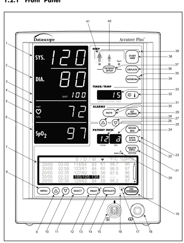
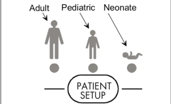
1.2.1 Front Panel
1-4 Accutorr Plus Service Manual
Chapter 1, Operation START NIBP TIMER/TEMP +-HOLD TO CLEAR. MEMORY FULL PATIENT INFO. ALARMS
INTERVALELAP.TIME TEMP
ROOM BED
SYS.
MAP NIBP 41 40 38 37 36 35 34 33 32 31 39 DEFLATE INTERVAL PATIENT SETUPMUTE ALARMSSET
BED ROOM DATA SCAN DELETE INFO. ON STANDBY DEFAULTS PRINT SELECT MENU S / D / M oF/C 20/05 20/05 20/05 20/05 20/05 03:00 02:58 02:35 02:33 02:30 114/64 123/61 127/62 185/105 129/62 83 84 83 135 84 61 60 58 56 59 98.7 98.5 97.6 98.2 ----96 97 96 96 97 %SPO2 Sp02 NIBP
SpO
2DIA.
30 29 28 27 26 25 24 23 22 21 20 19 18 17 16 15 14 13 12 11 10 9 8 7 6 5 4 3 2 1Accutorr Plus Service Manual 1-5 Chapter 1, Operation
Figure 1-2 Front Panel - Accutorr Plus NIBP with Trend Screen and Nellcor®or Masimo SpO
2 Revised 02/15/00 START NIBP TIMER/TEMP +-HOLD TO CLEAR. MEMORY FULL PATIENT INFO. ALARMS
INTERVALELAP.TIMETEMP
ROOM BED
SYS.
MAP NIBP 41 40 38 37 36 35 34 33 32 31 39 DEFLATE INTERVAL PATIENT SETUPMUTE ALARMSSET
BED ROOM DATA SCAN DELETE INFO. ON STANDBY DEFAULTS PRINT SELECT MENU S / D / M oF/C 20/05 20/05 20/05 20/05 20/05 03:00 02:58 02:35 02:33 02:30 114/64 123/61 127/62 185/105 129/62 83 84 83 135 84 61 60 58 56 59 98.7 98.5 97.6 98.2 ----96 97 96 96 97 %SPO2 Sp02 NIBP
SpO
2DIA.
30 29 28 27 26 25 24 23 22 21 20 19 18 17 16 15 14 13 12 11 10 9 8 7 6 5 4 3 2 1 Nellcor1. NIBP Systolic Display
Displays the systolic blood pressure data from NIBP measurements. It is also used to display NIBP error codes and systolic alarm limits.
2. NIBP Diastolic Display
Displays the diastolic blood pressure data from NIBP measurements. It is also used to display diastolic alarm limits.
3. NIBP MAP Display
Displays the mean arterial pressure (MAP) information from NIBP measurements. During a measurement, it will display the cuff pressure. It is also used to display the MAP alarm limits and the inflation pressure when selecting the initial inflation pressure.
4. Pulse Rate Display
Displays the pulse rate information from either the NIBP measurement or the SpO2 reading (Accutorr Plus model with SpO2). It is also used to display pulse rate alarm
limits.
5. NIBP/SpO2Pulse Rate Indicator
When the pulse rate displayed is based on an NIBP measurement, then NIBP is illu-minated. When the pulse rate displayed is based on an SpO2measurement
(Accutorr Plus model with SpO2), then SpO2is illuminated. 6. SpO2Display (Accutorr Plus model with SpO2)
Displays the %SpO2measurement information. This area is also used to display
the %SpO2alarm limits.
7. Liquid Crystal Display (LCD) (Accutorr Plus models with Trend Screen)
The Liquid Crystal Display (LCD) is used to display previous measurements (trend list) for the selected patient, or a menu that controls the beep volume and alarm volume.
8. Menu Key (Accutorr Plus models with Trend Screen)
This key is used to toggle between the trend list screen and the menu screen in the LCD. When the back light in the LCD is off, pressing this key turns it on. This key is also used to adjust the LCD contrast. Press and hold the key for two beeps to enter the adjustment mode. Use the Arrow keys (9 and 10) to change the contrast.
9. LCD Up Arrow Key (Accutorr Plus models with Trend Screen)
This key is used to scroll the trend data so that more recent measurements are displayed in the LCD. When the back light in the LCD is off, pressing this key turns it on. This key is also used to adjust the LCD contrast when in the adjustment mode. Use the Menu key (8) to enter the adjustment mode.
10. LCD Down Arrow Key (Accutorr Plus models with Trend Screen)
This key is used to scroll the trend data so that older measurements are displayed in the LCD. When the back light in the LCD is off, pressing this key turns it on. This key is also used to adjust the LCD contrast when in the adjustment mode. Use the Menu key (8) to enter the adjustment mode.
1-8 Accutorr Plus Service Manual
11. Select Key (Accutorr Plus models with Trend Screen)
When the menu screen is displayed in the LCD, this key is used to select the menu items. When the back light in the LCD is off, pressing this key turns it on.
12. Print Key
Press this key to print all stored information for the selected patient. Press to stop a printing that is in process. Press and hold this key (2 single beep tones, approx. 3 seconds) to change the print mode between Continuous and Request. When in the Continuous mode, the PRINT Indicator LED is illuminated. When loading in a new roll of recorder paper, press this key to feed the paper through the printer.
13. Print Indicator
This indicator is illuminated when continuous printing of measurements is selected.
14. Defaults Key
Press and hold this key (2 single beep tones, approx. 3 seconds) to reset all parameters back to the hospital default settings. This includes alarms, inflation pressure, interval, etc... When in the process of making a change to a setting, you can return to the original setting by momentarily pressing this key. To enter the User Configuration, press and hold this key (1 beep tone), while turning the unit on. See section 1.3.15 for details on default settings and User Configuration.
15. SpO2Connector (Accutorr Plus model with Datascope, Nellcor®or Masimo SpO2)
This connector is used to attach Datascope, Nellcor®or Masimo SpO2sensors. 16. AC Power Indicator
This greenLEDilluminates wheneverACpower is applied to the unit.
17. Battery Indicator
This greenLEDilluminates whenever the unit is operating on battery power. The LED will flash when the battery requires charging. When the LED begins flashing, approximately 30 minutes of battery time remain on the Accutorr Plus NIBP (20 minutes on the Accutorr Plus NIBP with Trend Screen and 10 minutes on the Accutorr Plus NIBP with Trend Screen and SpO2).
18. NIBP Connector
This connector is used to attach specified NIBP hoses.
19. On/Standby Key
This key is used to activate the unit, enabling it to begin taking measurements. The unit does not have to be “ON” for the internal battery to charge. However, the unit does need to be plugged into an AC receptacle for the battery to be charging.
20. Memory Full Indicator
This LED indicator flashes when 80 - 99 of the 100 available entries of trend are used. This LED is on continuously when 100 are used. Delete measurements manually using the DELETE INFO. key or the unit will automatically delete the oldest measurement for the current patient.NOTE:The unit will also automatically delete data that is 24 hours old.
Accutorr Plus Service Manual 1-9
21. Delete Info. Key
Press the Data Scan key to enable the Delete Info. key (Accutorr Plus without Trend and SpO2only). Once enabled, press and hold this key (1 beep tone, approx. 3 seconds)
to delete the most recent reading when it is displayed. When displaying any measurement, press and hold this key (2 beep tones, approx. 6 seconds) to delete all information for the currently selected patient. Press and hold at power up to delete all information for all patients.
22. Data Scan Key
Press this key (1 beep tone) to view previous measurements for the selected patient on the Accutorr Plus NIBP and to enable the Delete Info. key (Accutorr Plus with-out Trend and SpO2only). The LED indicator next to the key illuminates. On the
Accutorr Plus NIBP, use the Patient Info. Up & Down Arrow keys (27 & 28) to scroll through the stored measurements for the selected patient. On all models of the Accutorr Plus, press and hold this key (2 beep tones, approx. 6 seconds) to scan all of the rooms and beds for stored measurements. Press the Data Scan key again to stop on a particular room/bed. Press the Data Scan key again to exit this view mode.
23. Data Scan Indicator
This LED indicator is illuminated when viewing prior data.
24. Room/Bed Number Key
Press this key to change the displayed Room/Bed. After pressing this key use the Patient Info. Up & Down Arrow keys (27 & 28) to change the Room/Bed. This key is also used when selecting a User Configuration item.
25. Bed Letter Display
This display is used to show the current patient bed letter. It is also used to display status codes for NIBP, SpO2and Temperature and to display User Configuration
items.
26. Room Number Display
This display is used to show the current patient room number. It is also used to display status codes for NIBP, SpO2and Temperature, indicates which alarm is
being set (Hi or Lo), and displays a User Configuration item.
27. Patient Info. Down Arrow Key
This key is used to decrement the alarm limits when they are shown on the LED displays and to decrement the hours, minutes, month, day and year in the clock set mode. This key is also used to change the Room/Bed, to scroll through previous data and to change initial inflation pressure.
28. Patient Info. Up Arrow Key
This key is used to increment the alarm limits when they are shown on the LED displays and to increment the hours, minutes, month, day and year in the clock set mode. This key is also used to change the Room/Bed, to scroll through previous data and to change initial inflation pressure.
1-10 Accutorr Plus Service Manual
29. Set Alarms Key
This key is used to select the NIBP and SpO2(Accutorr Plus model with SpO2)
alarms to be changed. Repeated presses of this key sequences through the choices of Systolic Hi, Systolic Lo, Diastolic Hi, Diastolic Lo, Map Hi, Map Lo, Pulse Rate Hi, Pulse Rate Lo, SpO2Hi and SpO2Lo. After the last available parameter, the next
press returns the unit to normal operation. Once the desired parameter is flashing, use the Patient Info. Up & Down Arrow keys (27 & 28) to increment or decrement the alarm values.
30. Mute Key
Press this key (one beep tone), to silence the current alarm tone for 2 minutes. If a new alarm is detected during the 2 minutes, a new alarm tone will sound. Press and hold (2 beep tones, approx. 3 seconds) to permanently silence all alarm tones. Press this key again (1 beep tone), to activate alarm tones.
31. Mute Indicator
This LED indicator is illuminated when the alarm tone has been silenced permanently and when the alarm volume is set to OFF.
32. Timer/Temp Key
This key is used to switch between viewing the elapsed time or the temperature in the Interval/Elap. Time/Temp Display. When viewing stored measurements on the Accutorr Plus NIBP, press this key to switch between viewing the temperature and time of the measurement.
33. Interval/Elap. Time/Temp Display
This displays the time, in minutes since the last successful NIBP measurement (Elap. Time is illuminated). When the Interval key is pressed, the Elap. Time changes to the current Interval setting (Interval is illuminated). When the Predictive thermometer probe is removed from its holder, the Elap. Time changes to Temp (Temp is illuminated). Either “85.0" (° F) or ”29.4" (° C) will display; this is an internal self test feature. As the Predictive thermometer is taking a measurement, the display will flash as the number increases. When the final temperature measurement is determined, the display will no longer flash and a beep tone is generated. When the AccuTemp IR thermometer is used, the temperature is not displayed until after the measurement is taken and the thermometer is placed back into its holder. This display will also show the current time and date when setting the clock.
34. Interval Key
Press to enter the set time interval mode. An interval is set for automatic NIBP measurement cycles. To sequence through the interval choices of: OFF (——, when set to display graphics), CONT (Continuous), 1, 2.5, 5, 10, 15, 20, 30, 60, 120 and 240 minutes, repeatedly press the Interval key. When the desired interval is displayed in the Interval/Elap. Time/Temp Display the TIMER/TEMP key may be pressed to enter the interval setting or, the displayed setting will be entered when 15 seconds have elapsed without pressing the Patient Info. Up or Down arrow keys (27 & 28).
35. Interval Indicator
When an interval setting is selected, except for Off, the Interval Indicator flashes. When the interval mode is activated the Interval Indicator illuminates continuously.
Accutorr Plus Service Manual 1-11
36. Deflate Key
Press this key to stop anNIBPmeasurement that is in progress and deflate the cuff. A new measurement cycle will not be allowed for 10 seconds following the use of this key. The Start NIBP LED indicator is illuminated when a new measurement can begin. Press this key while in the interval mode to suspend the interval operation.
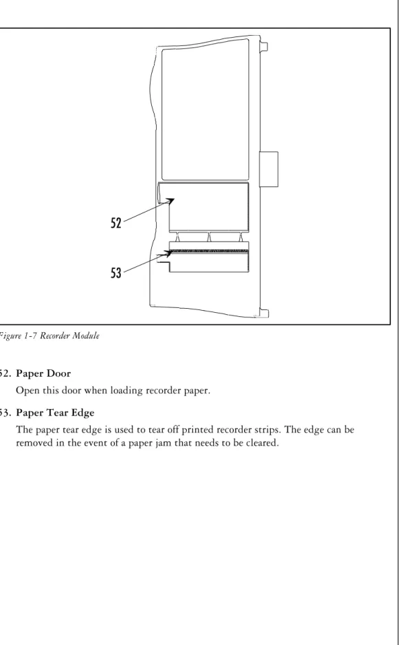
37. Patient Setup Key
Press this key (1 beep tone) to select the patient size. Each time the key is pressed the patient size will change. The choices will cycle from Adult, Pediatric, Neonate, Adult, Pediatric, Neonate, etc...
PRECAUTION:It is the users responsibility, when changing the room/bed, to assure the patient size and alarm settings are set as required.
This key is also used to view the cuff inflation pressure for an NIBP measurement. Press and hold (2 beep tones, approx. 3 seconds) to display the current inflation pressure in the MAP display. Use the Patient Info. Up & Down Arrow keys (27 & 28) to change the cuff pressure.
38. Start NIBP Key
Press this key to initiate anNIBPmeasurement. If a measurement is already in progress, a new measurement can not be initiated until a minimum of 10 seconds after the end of the one in progress (30 seconds when in the interval mode). The Start NIBP LED indicator is illuminated when a measurement can begin.
39. Start NIBP Indicator
This LED indicator is illuminated when the Accutorr Plus is ready to initiate an NIBP measurement.
40. Patient Size Indicators
One of theses LEDs illuminates to indicate the selected patient size.
41. Hidden Key
To enter the Service Diagnostics mode, press and hold this key (1 beep tone) while the Accutorr Plus is powering on and running the self tests (all “8"’s displayed in the LEDs). The Service Diagnostics mode is used to initiate various performance tests that are to be done by technical service personnel only. To exit Service Diagnostics, power down the Accutorr Plus by pressing the On/Standby key.
1-12 Accutorr Plus Service Manual
1.2.2 Rear Panel
42. Thermometer Module Connector
Used to attached one of the optional Datascope thermometer modules (PTM or AccuTemp IR).
43. Equipotential Lug
Provides equipotential bonding between hospital equipment.
44. ACPower Connector
Allows forA.C. power cord connection.
45. Communications Connector
Provides compatible communications to external devices and hospital’s information system.
46. Datascope Connector
Used by Datascope Technical Service Personnel.
47. Pole Mounting Handle and Cam
Provides the ability to quickly mount the Accutorr Plus to a rolling pole.
48. Recorder Module Connector
Used to connect the optional Datascope recorder module.
Accutorr Plus Service Manual 1-13
Chapter 1, Operation
43
44 45 47
42 48
46
1.2.3 Predictive Thermometer Module (PTM)
49. Probe Cover Holder
Used to store a box of probe covers. 50. Probe Chamber
Used to store the temperature probe when not in use.
51. Probe Connector
Used to connect the thermometer probe to the PTM module.
1-14 Accutorr Plus Service Manual
Chapter 1, Operation
49
50 51
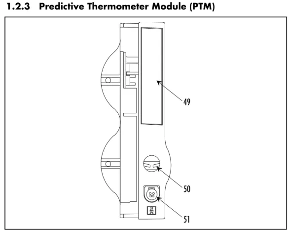
1.2.4 Recorder Module
52. Paper Door
Open this door when loading recorder paper.
53. Paper Tear Edge
The paper tear edge is used to tear off printed recorder strips. The edge can be removed in the event of a paper jam that needs to be cleared.
Accutorr Plus Service Manual 1-15
Chapter 1, Operation
52
53
This page intentionally left blank.
1-16 Accutorr Plus Service Manual
1.3. OPERATION
This section of the Service Manual provides guidelines and step-by-step instructions for proper operation of the Accutorr Plus NIBP, Accutorr Plus NIBP with Trend Screen, and the Accutorr Plus NIBP with Trend Screen and SpO2. The numbers in parentheses ( ) refer to the items described
in Section 1.2, “Controls and Indicators”. When a described feature refers to a particular model, it will be noted. When the name Accutorr Plus is used, it refers to all 5 models.
1.3.1 SETTING-UP / TURNING POWER ON
1. Before turning the power on, check the rear panel for voltage requirements. Confirm proper voltage is available.
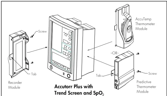
2. Before turning the power on, connect any required modules (recorder, thermometer). For instructions on connecting modules, see section 1.3.17.
Upon installation of any optional modules, a test is required after power up (step 5). For the recorder, press the print key and the recorder will feed the paper to verify proper function. For the Predictive thermometer, remove the probe from its holder and verify 85.0 (29.4) appears in the Interval/Elap. Time/Temp display.
3. If additional communications capabilities are required, attach a communications interface cable to the rear panel COMMUNICATIONS CONNECTOR (45) and to the corresponding interface connector on the peripheral instrument.
4. Attach the AC power cord into the rear panelAC POWER CONNECTOR (44)and into a grounded (3-prong) Hospital Grade AC receptacle. Do not use an adapter to defeat the ground. The greenAC POWER INDICATOR (16)illuminates, indicating AC power has been applied. The internal battery charges automatically when AC power is applied. WARNING:When attached to other products ensure that the total chassis leakage currents of all units (combined) do not exceed 100mA.
5. Press the ON/STANDBY key (19) to activate the unit. If it is required to enter the User Configuration mode, press and hold the DEFAULTS key (14) while the unit is powering on. See section 1.3.15 for more details on the User Configuration mode.
6. The unit begins a countdown from 20 and performs internal diagnostic tests. Any status codes are displayed in the appropriate LED. See section 1.3.16 for a list of status codes. At the end of power up, all of the displays (including the LCD on the Accutorr Plus models with Trend Screen) illuminate and then blank, except the Bed Letter and Room Number displays (25 & 26) which does not blank. A beep tone will sound during the power up sequence to confirm the operation of the audio indicator. If the time and date need to be set, see section 1.3.13 for instructions.
7. On an Accutorr Plus models with Trend Screen, adjust the contrast on the LCD if necessary. To adjust the contrast, press and hold the MENU key (8) (2 beep tones, approx. 3 seconds). Use the LCD UP & LCD Down ARROW keys (9 & 10) to adjust the contrast. See section 1.3.8, Setting the LCD Contrast, for more details.
Accutorr Plus Service Manual 1-17
1.3.2 PATIENT SETUP AND ROOM/BED ASSIGNMENT 1.3.2.1 Selecting the Patient Size
The Patient Size is selected using the PATIENT SETUP key (37). 1. Press the PATIENT SETUP key (37) to
select the Patient size. Three choices are available: Adult, Pediatric and Neonate. Each time the key is pressed the patient size changes. The indicator under the graphic of the patient size illuminates to indicate which size is selected. The factory default setting for the Patient size is Adult. See section 1.3.15, “User Configuration” to set a custom default setting.NOTE:Do not press and hold the PATIENT SETUP key to change the patient size. Pressing and holding this key, enter the initial cuff inflation pressure change mode.
1.3.2.2 Cuff Inflation Pressure
The initial cuff inflation pressure depends on the Patient Size setting. The initial cuff inflation pressures are listed in the table below. The initial cuff inflation pressures can be modified from the default (custom or factory) settings. When the Accutorr Plus is powered down, these modifications are deleted.
1. To change the initial cuff inflation pressure, press and hold the PATIENT SETUP key (37) (2 beep tones, approx. 3 seconds). The current initial cuff pressure for the
selected patient size displays in the MAP display.
2. Use the Patient Info. Up and Down Arrow keys (27 & 28) to change the pressure.
3. Once the desired pressure is displayed, press the PATIENT SETUP key (37) to enter this value.NOTE:Waiting 15 seconds will also enter this value.
PATIENT SIZE
SETTING INITIAL FACTORYDEFAULT CUFF INFLATION VALUES LOWEST SELECTABLE PRESSURE HIGHEST SELECTABLE PRESSURE INCREMENT Adult 180 mmHg 100 mmHg 260 mmHg 5 mmHg Pediatric 140 mmHg 60 mmHg 160 mmHg 5 mmHg Neonate 100 mmHg 40 mmHg 120 mmHg 5 mmHg
NOTE:The default patient size and initial cuff inflation pressure can be customized. See section 1.3.15, “User Configuration” for details on how to set custom defaults.
1-18 Accutorr Plus Service Manual
Chapter 1, Operation Revised 06/25/99 PATIENT SETUP Neonate Pediatric Adult
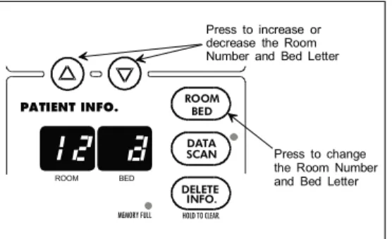
1.3.2.3 Room Number and Bed Letter
To monitor more than one patient, assign each patient to a particular room number and bed letter. Use the ROOM/BED key (24) to set the room number from 0 to 99 and the bed letter as a, b, c or d. On initial power up (no stored patient data), the room number and bed letter default to 0,a.
1. Press the ROOM/BED key (24). The ROOM LED flashes indicating that the room number can now be changed.
2. Press the Patient Info. Up or Down Arrow key (27 & 28) to increment or decrement the room number.
3. Press the ROOM/BED key again. The BED LED flashes.
4. Press the Patient Info. Up or Down Arrow key (27 & 28) to increment or decrement the bed letter.
5. Press the ROOM/BED key a third time to exit this mode, or do not press the key for 15 seconds.
Once measurements have been taken, and the unit is powered off and on, the room number and bed letter will default to the lowest room and bed where data is currently stored.
Accutorr Plus Service Manual 1-19
Chapter 1, Operation HOLD TO CLEAR. MEMORY FULL PATIENT INFO. ROOM BED BED ROOM DATA SCAN DELETE INFO. Press to change the Room Number and Bed Letter Press to increase or decrease the Room Number and Bed Letter
Figure 1-9 - Room Number and Bed Letter Keys and Indicators
1.3.3 MANUAL NIBP MEASUREMENTS AND GENERAL NIBP MEASUREMENT INFORMATION
1. Select a pressure cuff that is appropriate for the size of the patient. Use the chart below as a guideline.
Limb Circumference (cm) Description / Cuff Name Datascope Part Number Disposable Cuffs - Latex Free
30 - 45 Large Adult 0683-07-0001-01
24 - 36 Adult 0683-07-0001-02
18 - 27 Child 0683-07-0001-03
16 - 25 Small Child 0683-07-0001-04
Disposable Neonatal Cuffs (box of 10)
Approximate Limb Circumference:
Size 0: 5 - 8 cm 0683-03-0004-01
Size 1: 7 - 10 cm 0683-03-0001-01
Size 2: 9 - 13 cm 0683-03-0002-01
Size 3: 12 - 17 cm 0683-03-0003-01
Color Coded Cuffs** - Reusable Cuffs
45 - 66 Thigh - Tan* 0998-00-0003-36
30 - 47 Large Adult - Gray 0998-00-0003-35
24 - 36 Adult - Brown 0998-00-0003-34
18 - 27 Child - Red 0998-00-0003-33
6 - 11 New Born - Blue 0998-00-0003-31
Infant 0998-00-0003-32
A cuff that is too small for the limb will result in erroneously high readings. The correct size of the pressure cuff for a given patient has, among other considerations, a direct bearing on the accuracy of the obtained NIBP measurements. Base your selection of the cuff size on the limb circumference of the patient. The table above indicates the available Datascope cuffs for use with the Accutorr Plus. The design dimensions of the cuffs and their intended uses are based on recommendations of the American Heart Association.
NOTE:The cuffs that are used with the Accutorr Plus use special snap on connectors. Adapter hoses are available to connect older style cuff connectors. See Optional Accessories, Section 5.2 in the Operating Instructions for a detailed list of cuffs and adapter hoses. WARNING:Use only Datascope cuffs. Use of other than Datascope cuffs may result in erroneous measurements.
The pressure on the limb may not fall to zero between measurements if the cuff is wrapped too tightly. Therefore, assure that the cuff is properly applied.
The skin is sometimes fragile (i.e., on pediatrics, geriatrics, etc.). In these cases, a longer timer interval should be considered to decrease the number of cuff inflations over a period of time. NOTE: In extreme cases, a thin layer of soft roll or webril cotton padding may be applied to the limb in order to cushion the skin when the cuff is inflated. This measure may affect NIBP performance and should be used with caution.
* When using the thigh cuff, this product may not comply with product specifications listed in chapter 3. ** The limb circumferences of the color coded cuffs adhere to the AHA guidelines for size. They also incorporate
index and range lines to assist in cuff selection. The cuff bladder and hose contain Natural Latex rubber. The bladder has a dacron cover.
1-20 Accutorr Plus Service Manual
Chapter 1, Operation Revised 06/25/99
2. Attach the cuff hose to the NIBP cuff connector (18). To do this, hold the hose behind the knurled pressure fitting (female). Push onto the male connector until a click is heard. To remove, hold the knurled female fitting and pull firmly to release.
3. Apply the cuff to the patient. To reduce errors, the cuff should fit snugly, but with enough room for two fingers to be placed between the cuff and the patient’s arm (on adults), and with little or no air present within the cuff. Cuff should fit loosely on neonates. Apply the cuff so that the center of the inflation bag (bladder) is over the brachial artery. Be sure that the INDEX line on the cuff falls between the two RANGE lines. If not, a larger or smaller cuff is required. Be sure the cuff lies directly against the patient’s skin. For best results, the cuff should be placed on the arm at heart level and no clothing should come between the patient and the cuff.NOTE: Avoid compression or restriction of the pressure hose.
NOTE:The NIBP cuff should not be placed on a limb that is being utilized for any other medical procedure. For example, an I.V. catheter.
4. If required, select the patient size with the PATIENT SETUP key (37). On initial power up, the configurable default setting is used. Otherwise, the last selected patient size is used. Initial default cuff inflation pressures depend on the Patient Size setting. See section 1.3.2.2 for details on changing the initial cuff inflation pressure.
5. Press the START NIBP key (38) to begin an NIBP measurement. A beep is sounded after a completed measurement.
NOTE:Inflate the cuff only after proper application to the patient’s limb. Cuff damage can result if the cuff is left unwrapped and then inflated.
The cuff begins to inflate to the selected cuff pressure. After reaching the selected pressure, the cuff begins to slowly deflate and the Accutorr Plus collects oscillometric pulsations.
If the initial cuff inflation is found to be inadequate, the unit retries with a higher inflation pressure (+50 mmHg in the adult mode; +50 in the pediatric mode; +40 mmHg in the neonate mode). A triple beep tone is generated. NOTE: Any time there is an unsuccessful NIBP measurement, a triple beep tone is generated and the Diastolic, Systolic, NIBP HR, MAP and Timer/Temp LED’s will be replaced with dashes. Have the patient remain still to avoid unnecessary motion artifact. After the cuff pressure drops below the diastolic pressure, the results of the measurement are displayed and the cuff is vented to atmosphere.
If an error code displays in the Systolic Display or a status code in the Room/Bed Display, refer to Section 1.3.16, Status and Error Codes, for its explanation. A successful measurement clears a status code. To clear a status code, press the ROOM/BED NUMBER key (24).
6. When required, press the DEFLATE key (36) to interrupt a measurement. The cuff will deflate.
NOTE:Once the initial measurement is taken for a room/bed, the Accutorr Plus will continue to use the selected patient size.
NOTE:Check the patient’s limb for any indications of circulation impairment.
Accutorr Plus Service Manual 1-21
1.3.3.1 NIBP Pres sure Limit Fail Safe
If the cuff is over-pressurized, it will au to mat i cally de flate and the sta tus code 8812
(STOP - CUFF OVERPRESSURE) or er ror code 987 (STOP - HARD WARE OVERPRESSURE) will be dis played in the Room/Bed or dis play.
The unit must be turned off and back on again to re set the hard ware overpressure switch (er ror code 987) be fore any new mea sure ments can be taken.
1.3.3.2 Cuff In fla tion Time
If the cuff pres sure does not at tain 20 mmHg within 40 sec onds of the start of in fla tion or if the tar get pres sure is not reached within an other 60 sec onds, then the cuff is de flated and sta tus codes will be dis played in the Room/Bed dis play. See sec tion 1.3.16 for a list of er ror and sta tus codes.
1.3.3.3 Au to matic Ad just ment of Cuff In fla tion Pres sure (Adap tive In fla tion)
The unit ad justs the in fla tion pres sure ac cord ing to the pre vi ous read ing of the sys tolic pres sure. Af ter the first suc cess ful mea sure ment, the in fla tion pres sure is the pre vi ous sys tolic +50 mmHg in the adult mode and +50 mmHg in the pe di at ric mode and +40 mmHg in the ne o nate mode. When not in interval mode, the adaptive inflation may be disabled.
To view the cur rent in fla tion pres sure, press and hold (2 beep tones, ap prox i mately 3 sec onds) the Pa tient Setup Key (37). The cur rent in fla tion pres sure is shown in the MAP dis play. If re quired, use the Pa tient Info. Up & Down Ar row keys (27 & 28) to change the in fla tion pres sure.
It is also pos si ble to per ma nently over ride this ad just ment in the User Con fig u ra tion. See sec tion 1.3.15 for de tails.
1-22 Accutorr Plus Service Manual
Chapter 1, Operation
1.3.4 AUTOMATIC NIBP MEASUREMENTS (Interval Mode)
The Accutorr Plus can be set to au to mat i cally take NIBP mea sure ments. On ini tial power up, the in ter val set ting will de fault to OFF. The User Con fig u ra tion mode can be used to set cus tom de faults for the In ter val Mode. See sec tion 1.3.15, User Con fig u ra tion for de tails. In this mode, the adaptive inflation is always enabled.
Fol low Steps 1 - 4 in the Man ual Pro ce dure, Sec tion 1.3.3, to se lect, at tach and ap ply the cuff and to ad just the ini tial cuff in fla tion pres sure.
5. Press the IN TER VAL key (34). The cur rent se lec tion is dis played in the In ter val/
Elap.Time/Temp. dis play (33). Press the IN TER VAL key to scroll to the next avail able in ter val se lec tion. The se lec tions are: Off (—- when set to graphic dis play), CONT (con tin u ous), 1, 2.5, 5, 10, 15, 20, 30, 60, 120 and 240 min utes. When an in ter val set ting is se lected, ex cept for Off, the In ter val In di ca tor (35) flashes. When the in ter val mode is ac ti vated the In ter val In di ca tor il lu mi nates con tin u ously.
6. The dis played in ter val time is en tered when the IN TER VAL key has not been pressed
for 15 sec onds or,
when the TIMER/TEMP key (32) is pressed, which changes the dis play back to Elap. Time or, when the START NIBP key (38) is pressed, which ini ti ates an NIBP mea sure -ment, ac ti vates the In ter val Mode, and changes the dis play back to Elap. Time.
7. If the START NIBP key (38) has not al ready been pressed, press to take a mea sure ment
and to ac ti vate the in ter val mode. NOTE: If the in ter val time is changed, the START NIBP key does not need to be pressed for the new in ter val to ini ti ate. When the new time in ter val has elapsed, a mea sure ment will be taken.
NOTE: When the NIBP con tin u ous in ter val is cho sen, the Accutorr Plus will take back to back (one right af ter the other) blood pres sure read ings. As a safety pre cau tion, a five
min ute limit is placed on con tin u ous mea sure ments. Af ter 5 min utes, the NIBP in ter val
will au to mat i cally switch to mea sure ments taken once ev ery 5 min utes. This is done to re duce the chance of sur face ves sel rup ture (petechia).
If it is desirable to maintain a fixed cuff inflation pressure, the adaptive inflation feature may be disabled in this “continuous” mode.
1.3.4.1 Can celing an Au to matic NIBP Mea sure ment
To can cel a sched uled mea sure ment, press the DE FLATE key (36). This will sus pend the timed NIBP mea sure ments un til the START NIBP key (38) is pressed. The in ter val in di ca tor will flash. See sec tion 1.3.4.4 for more de tails on the start and de flate func tion.
NOTE: Pressing the DE FLATE key (36) will also end a mea sure ment cy cle that is al ready in prog ress.
To take an im me di ate mea sure ment and to re ac ti vate the In ter val mode, press the START NIBP key (38). The next timed mea sure ment will be taken at the time set by the in ter val. For ex am ple, if the in ter val was set to 30 min utes, the next timed mea sure ment will be 30 min utes af ter the START NIBP key was pressed. NOTE: If the In ter val mode is no lon ger re quired, set the in ter val to “OFF” prior to press ing the START NIBP key. See sec tion 3.4 for de tails on chang ing the in ter val mode.
Accutorr Plus Service Manual 1-23
NOTE:If the DEFLATE key (36) is pressed, it will take 10 seconds before another measurement can be taken. The START NIBP INDICATOR (39) will be illuminated, when ready.
NOTE:When in the Interval mode and the Room/Bed is changed, the interval mode is suspended (interval indicator flashes) until the NIBP Start key is pressed.
1.3.4.2 Changing the Interval Setting
If the interval time is changed while the Accutorr Plus is in the interval mode, the new interval time is used once it is entered. For example: The interval time is set to 60 minutes. Thirty minutes have elapsed since the last timed automatic measurement and the interval time is changed to 10 minutes. Once the interval time is entered, the Accutorr Plus will take an automatic NIBP measurement in 10 minutes and then once every 10 minutes.
1.3.4.3 Effects of Changing the Room Number and/or Bed Letter on the Interval Setting
When the Room Number and/or Bed Letter is changed, the interval setting will remain the same.NOTE:The interval setting can be changed if required. Also, if an NIBP measurement is in progress, the measurement will stop and the cuff will deflate. The timed interval measurements will not activate again (interval indicator flashes) until the START NIBP key (38) is pressed.
1.3.4.4 START and DEFLATE Functions
The START NIBP and DEFLATE functions have the following effects on the timed measurement sequence.
· INTERVAL mode is active and the START NIBP key (38) is pressed causing an unscheduled measurement to be taken. Taking this unscheduled measurement does not affect the timing of the interval cycle, therefore, the scheduled measurements will still be taken as if there were no interruptions. Only one measurement is taken for each measurement cycle - even if the unscheduled measurement coincides with the scheduled measurement.
· INTERVAL mode is active and the DEFLATE key (36) is pressed. The INTERVAL INDICATOR (35) flashes. No additional measurements will be taken until the START NIBP key (38) is pressed. If a timed measurement is in progress, the measurement is suspended and the cuff deflates.
· INTERVAL mode is active and the interval time is changed. The measurement cycle is reset with the new interval. A measurement will be taken after the new interval time has elapsed.
1-24 Accutorr Plus Service Manual
1.3.5 ALARMS
The Accutorr Plus provides “HI” and “LO” alarm limit settings for systolic, diastolic, MAP, pulse rate and SpO2. An alarm violation occurs when one or more patient
parameters equals or falls outside the limits that have been specified.
1.3.5.1 Setting Alarm Limits
The Factory Default for all parameter alarms, except Low SpO2, is OFF. The Low SpO2
factory default is 86. The User Configuration mode can be used to set custom defaults. See section 1.3.15, User Configuration for details. The factory and custom defaults for alarms can be changed as required to accommodate the needs of individual patients. The SET ALARMS key (29) and the Patient Info. Up and Down Arrow keys (27 & 28) are used to set alarm values.
1. Press the SET ALARMS key (29) (1 beep) to enter into the alarm set mode. The first time this key is pressed, all NIBP displays blank except for the systolic display which shows the current high systolic alarm value. The word HI is displayed in the Interval/Elap. Time/Temp display (33). When the unit has been configured to display graphics, the symbol is displayed. When the graphic is displayed, the top lines blink. This indicates the high alarm is selected.
The second time the SET ALARMS key (29) is pressed the Systolic LO parameter is selected. The word LO is displayed in the Interval/Elap. Time/Temp display (33). When the unit has been configured to display graphics, the symbol is displayed. When the graphic is displayed, the bottom lines blink. This indicates the low alarm is selected.
Each time the SET ALARMS key (29) is pressed a new parameter is selected for alarm setting (all other displays blank). The order they are available is: Systolic HI, Systolic LO, Diastolic HI, Diastolic LO, MAP HI, MAP LO, Pulse Rate HI, and Pulse Rate LO, SpO2HI and SpO2LO. When all of the available parameters have been selected,
the next press of the SET ALARMS key returns the Accutorr Plus to normal operation.
2. To change an alarm limit setting, use the Patient Info. Up & Down Arrow keys (27 & 28). The Up arrow increments the alarm limit setting. The Down arrow decrements the alarm limit setting.
To cancel all of the changed alarm values while still in progress of changing, press the DEFAULTS key (14) (1 beep tone).
If the SET ALARMS or Arrow keys have not been pressed for 15 seconds, the Accutorr Plus returns to normal operation and saves any alarm limit changes.
NOTE:If the patient size is changed, the alarm settings will change to the default settings for the new patient size.
Accutorr Plus Service Manual 1-25
Alarm Limit Table
PARAMETER RANGE UNITS FACTORY
DEFAULT UNITS OFINCREMENT
Systolic High Adult Pediatric Neonate Off, 60-260 Off, 60-160 Off, 50-125 mmHg Off 5 Systolic Low Adult Pediatric Neonate Off, 55-150 Off, 55-130 Off, 45-115 mmHg Off 5 Diastolic High Adult Pediatric Neonate Off, 40-200 Off, 40-150 Off, 35-100 mmHg Off 5 Diastolic Low Adult Pediatric Neonate Off, 30-120 Off, 30-50 Off, 25-50 mmHg Off 5 MAP High Adult Pediatric Neonate Off, 90-200 Off, 90-150 Off, 60-110 mmHg Off 5 MAP Low Adult Pediatric Neonate Off, 40-100 Off, 40-70 Off, 30-70 mmHg Off 5
Pulse Rate High Adult Pediatric Neonate Off, 100-245 Off, 100-245 Off, 100-245 bpm Off 5
Pulse Rate Low Adult Pediatric Neonate Off, 35-120 Off, 35-150 Off, 75-200 bpm Off 5 SpO2 High Adult Pediatric Neonate Off, 61-99 Off, 61-99
Off,61-99 %SpO2 Off 1
SpO2 Low Adult Pediatric Neonate 60-95 60-95 60-95 %SpO2 86 1 1.3.5.2 Alarm Violations
An alarm condition exists if the parameter is equal to or is outside the high/low limit range that has been set. When an alarm limit is violated, the following actions occur:
· The LEDs for the parameter in an alarm condition flashes.
· The parameter in an alarm condition is in reverse video on the LCD (Accutorr Plus models with Trend Screen).
· The alarm tone is sounded (unless muted with the MUTE key (30)).
· The parameter(s) that was in an alarm condition will be in brackets [ ] when printed on the recorder.
1-26 Accutorr Plus Service Manual
1.3.5.3 How to Mute Alarms
When an NIBP alarm ex ists, press the MUTE key (30) (1 beep tone) to si lence the alarm tone for 2 min utes. The alarm tone will re turn af ter the next measurement value that violates the selected limits.
When an SpO2 alarm ex ists, press the MUTE key (30) (1 beep tone) to si lence the alarm
tone for two min utes. The alarm tone will re turn af ter two min utes, un less the SpO2
value changes and is within the alarm lim its. If dur ing that two min utes the mea sured
SpO2 value changes to a value that is within the ac cept able range, and then re turns to
a value that is out side the set alarm limit, the alarm tone will re turn be fore the two
min utes elapse. Ex am ple (within 2 min utes): • SpO2 low alarm limit has been set to 90.
• SpO2 is mea sured at 89; the alarm tone sounds and the SpO2 dis play flashes. • The
MUTE key is pressed. • SpO2 is mea sured at 88; there is no alarm tone, but the SpO2
dis play flashes. • SpO2 is mea sured at 91; no alarm tone sounds and the dis play stops
flash ing. • SpO2 is mea sured at 89; the alarm tone sounds and the SpO2 dis play flashes.
Press and hold the MUTE key (30) (2 beep tones, approx. 3 sec onds) to per ma nently si lence the alarm tone. The MUTE LED (31) il lu mi nated. The LEDs for the alarm ing pa ram e ter will con tinue to flash. To re ac ti vate the alarm tone func tion, press the MUTE key (30) again.
1.3.5.4 Alarms and Changing the Room Num ber and/or Bed Let ter
When chang ing the rooms and beds, the alarm set tings will change if the fi nal room/bed dis played is a dif fer ent pa tient size than the orig i nal room/bed. When a new pa tient size is de tected, the alarm set tings change to the de faults for the dif fer ent pa tient size. See sec tion 1.3.15 for in for ma tion on cus tom de faults.
The ta ble be low de scribes 6 mea sure ments in dif fer ent rooms/beds and dif fer ent pa tient sizes, and the ef fect on the alarm set tings.
Mea sure ment Or der Room/Bed Pa tient Size Alarm Set tings
1 1/a Adult Have been man u ally set.
2 1/b Adult Re main the same.
3 2/a Pe di at ric Changed to de faults for a pe di at ric size pa tient.
4 3/a Adult Changed to de faults for an adult
size pa tient.
5 4/a Adult Re main the same.
6 1/a Adult Re main the same. If the alarm
set tings that were set from the 1st mea sure ment are re quired, they need to be set again man u ally.
NOTE: The alarm set tings can be changed, if nec es sary, when chang ing the room/bed and the pa tient size is the same.
PRE CAU TION: It is the us ers re spon si bil ity, when chang ing the room/bed, to as sure the pa tient size and alarm set tings are as re quired.
Accutorr Plus Service Manual 1-27
1.3.6 TO VIEW AND DELETE STORED DATA (Trend Mode) All models of the Accutorr Plus are capable of storing up to 100 entries of measurement data. Each time a successful NIBP measurement is made, the data is automatically stored in memory. When a temperature measurement is made between two minutes before and two minutes after an NIBP measurement, it is stored as the same entry with the NIBP measurement. If a temperature measurement is made outside this time, it is stored as a separate entry. When either NIBP or temperature measurements are stored and SpO2
information is available, then the SpO2data is also stored.
When 80 entries are stored into trend memory, the MEMORY FULL Indicator (20) will flash. When 100 entries are stored into trend memory, the MEMORY FULL Indicator (20) will illuminate continuously. Once 100 entries are stored, old data can be deleted manually for any patient; or when new data is available, the Accutorr Plus will automatically delete the oldest data for the currently displayed patient.
NOTE:The unit will also automatically delete data that is 24 hours old.
The Accutorr Plus NIBP uses the Systolic, Diastolic, MAP, and Temp displays to view stored data. The Accutorr Plus models with Trend Screen use the LCD to display up to 5 measurements at a time. The stored data that is viewed is for the currently selected patient (indicated by the room number/bed letter).
1.3.6.1 To View the Stored Measurements on the Accutorr Plus NIBP
1. Press the DATA SCAN key (22) (1 beep tone). The DATA SCAN Indicator (23) illuminates.
2. Press the Patient Info. Up and Down Arrow keys (27 & 28) to view stored data for the current patient. The stored data is displayed in the Systolic, Diastolic, MAP, Pulse Rate and Temp displays.
Consecutive presses or pressing and holding the UP or DOWN arrow will
allow the stored measurements to continuously wrap around. When the measurements wrap, a double beep tone will sound. If a temperature measurement is not available for the NIBP measurement that is displayed, then - - - - is shown in the Interval/Elap. Time/Temp display (33). To view the time of measurements, press the TIME/TEMP key (32).
3. To exit the view stored data mode, press the DATA SCAN key (22) (1 beep).
1-28 Accutorr Plus Service Manual
Chapter 1, Operation Revised 12/20/00
1.3.6.2 To View the Stored Measurements on the Accutorr Plus NIBP with Trend Screen and the Accutorr Plus NIBP with Trend Screen and SpO2 The stored measurements on the Accutorr Plus models with Trend Screen are displayed in the LCD. Up to 5 stored measurements are displayed at one time. Measurements are displayed in time order, with the newest measurement at the top. A scroll bar with one or both arrows will display on the side of the LCD when more measurements are available to view. When only one arrow displays, more measurements are only available in the direction of the arrow.
1. To view more measurements press the LCD Up or Down Arrow key (9 & 10).
1.3.6.3 To Delete the Stored Measurements on all Models of the Accutorr Plus
While viewing stored data, you can delete the most recent measurement or all of the stored measurements for the currently displayed patient.
1. Select a room/bed where stored information can be deleted. (See section 1.3.2.3 for details on selecting a room/bed.) If it is the currently displayed room/bed, go to step 2. When you are uncertain what rooms/beds have stored data, press and hold the DATA SCAN key (22) (2 beep tones, more than 3 seconds). The Accutorr Plus will scan through all of the rooms/beds that have data stored. To stop on a Room/Bed as the Accutorr Plus is scanning, press the DATA SCAN key (22).NOTE:The Accutorr Plus will scan through the rooms/bed with stored data only once.
2. On the Accutorr Plus NIBP only, when the desired room/bed is displayed, press the DATA SCAN key (22) (1 beep tone). The DATA SCAN Indicator (23) illuminates.
3. When the most recent stored data is displayed, press and hold the DELETE INFO. key (21) (1 beep tone, approx. 3 seconds) to delete this measurement.
4. When viewing any of the stored measurements, press and hold the DELETE INFO. key (21) (2 beep tones, approx. 6 seconds) to delete all stored measurements for the current patient. When all data is cleared the patient size will be the default selection.
5. On the Accutorr Plus NIBP only, press the DATA SCAN key (22) (1 beep tone) to exit the delete data mode.
NOTE:The unit will also automatically delete data that is 24 hours old.
NOTE:To delete all information for all patients, press and hold the DELETE INFO. key (21) while powering on the unit.
Accutorr Plus Service Manual 1-29
Chapter 1, Operation S / D / M oF/C 20/05 20/05 20/05 20/05 20/05 03:00 02:58 02:35 02:33 02:30 114/64 123/61 127/62 185/105 129/62 83 84 83 135 84 61 60 58 56 59 98.7 98.5 97.6 98.2 ----96 97 96 96 97 %SPO2 Date Time Scroll Bar
Alarm Violated Measurement
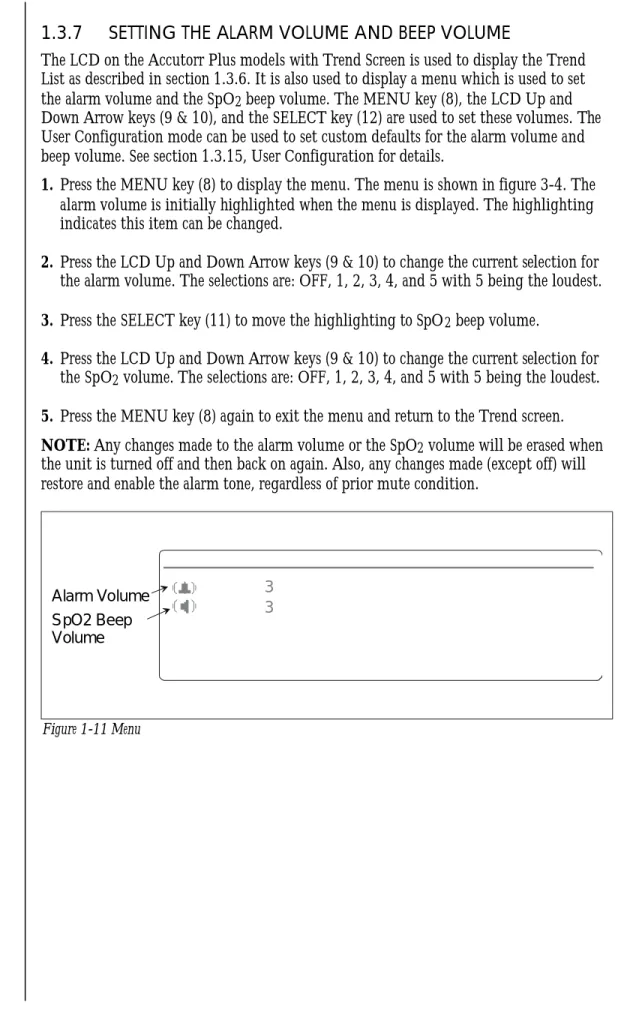
1.3.7 SETTING THE ALARM VOLUME AND BEEP VOLUME
The LCD on the Accutorr Plus mod els with Trend Screen is used to dis play the Trend List as de scribed in sec tion 1.3.6. It is also used to dis play a menu which is used to set
the alarm vol ume and the SpO2 beep vol ume. The MENU key (8), the LCD Up and
Down Ar row keys (9 & 10), and the SE LECT key (12) are used to set these vol umes. The User Con fig u ra tion mode can be used to set cus tom de faults for the alarm vol ume and beep vol ume. See sec tion 1.3.15, User Con fig u ra tion for de tails.
1. Press the MENU key (8) to dis play the menu. The menu is shown in fig ure 3-4. The
alarm vol ume is ini tially high lighted when the menu is dis played. The high light ing in di cates this item can be changed.
2. Press the LCD Up and Down Ar row keys (9 & 10) to change the cur rent se lec tion for
the alarm vol ume. The se lec tions are: OFF, 1, 2, 3, 4, and 5 with 5 be ing the loud est.
3. Press the SE LECT key (11) to move the high light ing to SpO2 beep vol ume.
4. Press the LCD Up and Down Ar row keys (9 & 10) to change the cur rent se lec tion for
the SpO2 vol ume. The se lec tions are: OFF, 1, 2, 3, 4, and 5 with 5 be ing the loud est.
5. Press the MENU key (8) again to exit the menu and re turn to the Trend screen.
NOTE: Any changes made to the alarm vol ume or the SpO2 vol ume will be erased when
the unit is turned off and then back on again. Also, any changes made (except off) will restore and enable the alarm tone, regardless of prior mute condition.
1-30 Accutorr Plus Service Manual
Chapter 1, Operation 3 3 Alarm Volume SpO2 Beep Volume
Fig ure 1-11 Menu
1.3.8 SETTING THE LCD CONTRAST (View Angle Adjustment) The LCD on the Accutorr Plus models with Trend Screen can be adjusted for optimum viewing. The MENU key (8) and the LCD Up and Down Arrow keys (9 & 10) are used to adjust the contrast.
1. Press and hold the MENU key (8) (2 beep tones, approx. 3 seconds). A beep tone is generated when the key is first pressed and the display changes to the menu. When a second beep tone is generated, release the key.
2. To quickly adjust the contrast, press and hold either the LCD Up or Down Arrow key (9 or 10). For fine adjustment, momentarily press either the LCD Up or Down Arrow key.
3. The LCD contrast adjustment is saved by either pressing the MENU key (8) again or not pressing either the LCD UP or Down Arrow keys (9 & 10) for 15 seconds.
NOTE:The contrast setting will be the same each time the unit is turned on, unless readjusted by the user.
Accutorr Plus Service Manual 1-31
1.3.9 DISPLAY TIME OUT MODE
To conserve power, most displays will blank at user selected times. The LCD illumination time out can be set between 3 and 15 minutes. The LED display time out can be set between 5 and 60 minutes. Since the Accutorr Plus can be powered from either an AC or DC source, the user configuration allows the setting of separate times for each type of power source. See User Configuration, section 1.3.15 for more information on setting the time out minutes.
To turn on the LCD light, press the MENU key (8). To turn on the LED displays, press any key.
1-32 Accutorr Plus Service Manual
1.3.10 SpO2MEASUREMENTS (Accutorr Plus model with SpO2)
To obtain SpO2measurements and SpO2Heart Rate from the Accutorr Plus model with SpO2:
See Section 3.10.1 for units with Datascope SpO2; for units with Nellcor SpO2see
section 3.10.2; for units with Masimo SpO2see section 1.3.10.3)
CAUTION: Do not place the sensor on an extremity with an invasive catheter or blood pressure cuff in place.
CAUTION: A pulse oximeter should not be used as an apeana mnitor.
CAUTION: A pulse oximeter should be considered an early warning device. As a trend towards patient deoxygenation is indicated, blood samples should be analyzed by a laboratory co-oximeter to completely understand the patient’s condition.
CAUTION: Ensure proper routing of the patient cable to avoid entanglement and/or strangulation
NOTE: In the event you are unable to obtain a reading, or the reading is inaccurate, check the patients vital signs by alternate means and consider the following:
· If your patient is poorly perfused, try applying the sensor to another site (i.e. A different finger or toe).
· Check that the sensor is properly aligned.
· In electrosurgery, make sure the sensor is not too close to ESU devices or cables.
· Check to make sure the site area is clean / non-greasy. Clean the site and sensor if needed. Nail polish and fungus should be removed.
1.3.10.1 Datascope Pulse Oximetry Sensors A. Introduction
A wide range of Datascope sensors are available for connection to the Accutorr Plus model with SpO2. The sensors cover both short-term and long-term monitoring needs on
patients ranging from infants to large adults.
The DATASENSOR is intended for short-term adult monitoring.
The FLEXISENSOR®SD, available in five different sizes, provides both short-term and long-term monitoring for large adults, adult ear, adults, pediatrics, and infants. The FLEXISENSOR®SD is used when the DATASENSOR is not convenient or suitable. The ear sensor is intended for long-term adult monitoring. A range of disposable bandages are available for use with the FLEXISENSOR®SDs. They are available in 2styles, SENSOR GUARD™ (used for large adults, adults and pediatrics), and Coban with SENSOR GUARD™ (used for infants).
Use of the sensors does not cause any penetration of the skin, nor is there any electrical contact or transfer of excessive heat to the patient.
The sensor is composed of a dual light emitting diode (LED) (emitter) and a photo diode (detector). The emitter discharges two colors (wave lengths) of light into the patient’s extremity (finger, toe, ear). The detector receives the light not absorbed by the blood or tissue components. The Accutorr Plus model with SpO2then uses the
Accutorr Plus Service Manual 1-33
relative absorption of the two light wavelengths to compute and display SpO2 (functional
saturation) and Pulse Rate measurements. The key benefits of the sensors are:
· Electro-Surgical Noise (ESU) Rejection - The sensor configuration of both the DATASENSOR and the FLEXISENSOR®SD provide uninterrupted monitoring and absence of false alarms during the use of ESU (ESU can be set at any power level). This design prevents electro-surgical noise entering the monitor, via the sensor, and interfer-ing with unit operation.
· Monitoring Restless Patients -Motion artifact rejection is achieved in several ways.
1. The sensor design used with their recommended bandages assures a snug fit of the sensor to the patient.
2. Light emitting diodes (LEDs) and detectors gather a strong signal from the patient.
3. When in the presence of motion, the software adjusts the “averaging-period”, increasing it to a maximum of 15 seconds during motion, and automatically reducing it during quiet periods to obtain a fast response. This combination reduces the number of monitoring interruptions and false alarms from patient motion.
· Tracking of Weak Peripheral Pulse Levels -Many patients suffer poor peripheral perfusion due to hypothermia, hypovolemia, reduced cardiac output, etc. The Accutorr Plus model with SpO2is designed to automatically increase its gain to track patients with
poor peripheral perfusion.
· Rejection of Ambient Light -Many monitoring situations involve high levels of ambient light, i.e.., operating room lights, neonatal phototherapy, heat warmers, etc. The Accutorr Plus model with SpO2, the sensors, and the bandages each contribute to the
rejection of ambient light. The monitor automatically measures and corrects for high levels of ambient light. The enclosed design of the DATASENSOR prohibits the interference of high levels of ambient light on adults with sensor operation. The opaque material used in the composition of the bandages, which are used with the FLEXISENSOR®SD, helps keep out ambient light.
· Patient Comfort -The FLEXISENSOR®SD line is designed to work with a disposable bandage of two styles (SENSOR GUARD TM and Coban) which conform comfortably and safely to the particular patient’s anatomy.
B. Sensor Selection and Application
Selection of a specific sensor is based on the patient’s size, physical condition, and expected monitoring duration. General guidelines for the selection of a sensor are provided in the Sensor Selection Table, page 3-25. Instructions for the application of a sensor to a patient are provided in each sensor package. For optimal DATASENSOR and FLEXISENSOR® placement ensure that cable side is placed in the correct position. See figures below.
1-34 Accutorr Plus Service Manual
Chapter 1, Operation Revised 02/15/00
Cable on Top
Figure 1-12 Datasensor or
Durasensor Placement Figure 1-13 Flexisensor
ÞPlacement Cable on Bottom
C. Sensor Connection to the Accutorr Plus model with SpO2
1. Align the cable connector on the sensor assembly with the SpO2Connector (15) on
the Accutorr Plus model with SpO2.
2. Push the cable connector into the SpO2Connector (15). Confirm that the cable
connector is securely in place.
3. The digital SpO2values and SpO2pulse rate will be displayed in the SpO2and pulse
Rate LED’s.
4. If desired, adjust the beep volume. See section 3.7, Setting the Alarm Volume and Beep Volume, for details on adjusting the beep volume.
D. Sensor Inspection
Before use, always inspect sensors, cables, and connectors for damage, i.e., cuts and abrasions. Do not use the sensor, cable or connector if damaged. Replace with a good working sensor.
For long sensor life:
· Do not drop on the floor, or give other s