Aboulkhair, Nesma T. (2016) Additive manufacture of an
aluminium alloy: processing, microstructure, and
mechanical properties. PhD thesis, University of
Nottingham.
Access from the University of Nottingham repository:
http://eprints.nottingham.ac.uk/31152/1/Final_PhD%20Thesis_Nesma_Approved.pdf
Copyright and reuse:
The Nottingham ePrints service makes this work by researchers of the University of Nottingham available open access under the following conditions.
This article is made available under the Creative Commons Attribution licence and may be reused according to the conditions of the licence. For more details see:
http://creativecommons.org/licenses/by/2.5/
1
Additive manufacture of an aluminium
alloy: processing, microstructure, and
mechanical properties
Nesma T. Aboulkhair, MSc
Thesis submitted to the University of Nottingham for the degree of Doctor
of Philosophy (PhD)
I ABSTRACT
Additive manufacturing of aluminium alloys using selective laser melting (SLM) is of research interest nowadays because of its potential benefits in industry sectors such as aerospace and automotive. However, in order to demonstrate the credibility of aluminium SLM for industrial needs, a comprehensive understanding of the interrelation between the process parameters, produced microstructure, and mechanical behaviour is still needed. This thesis aims at contributing to developing this comprehensive understanding through studying the various aspects of the process, with investigation of the powder raw material to the near fully dense samples, focussing on the alloy AlSi10Mg.
The primary building blocks in the SLM process are the single tracks. Their formation is affected by the physical properties of the material that control the laser-material interactions. Keyhole mode melting was found to be dominant when processing AlSi10Mg, producing conical-shaped melt pools. Porosity was not evident in single tracks and individual layers. Satellites and balling defects, however, were observed on top of the tracks and layers at higher scan speeds, which contribute to porosity formation with layer progression.
The combination of process parameters controls the amount of porosity formed, with the scan speed controlling the type of pore; metallurgical or keyhole pore. A pre-melt scan strategy significantly reduced porosity and successfully produced 99.8% dense samples. Furthermore, the pre-melt scan strategy was seen to effectively reduce the number of pores developed when using powder that does not fully comply with the process standards. The gas
II
flow rate within the process chamber controlled laser spatter and condensate removal during processing, which in its turn affected the degree of porosity in the samples.
The SLM process resulted in an AlSi10Mg alloy with a characteristically fine microstructure, with fine equiaxed grains at the melt pool core and coarser elongated grains at the boundary. The material showed a strong texture, owing to directional solidification. Cellular dendritic Al with inter-dendritic Si was observed. The material was subjected to a T6 heat treatment that transformed the microstructure into spheroids of Si in the Al matrix.
This study investigated, for the first time, the local mechanical properties within the SLM material using nanoindentation. This showed a uniform nano-hardness profile that was attributed to the fine microstructure and good dispersion of the alloying elements. Spatial variation within the material was recorded after the T6 heat treatment due to phase transformation. This study is also the first to report on the compressive behaviour of solid SLM material, which is important for developing prediction and simulation models. The heat treatment softened the material and provided it with an increased ductility under indentation, tensile, and compressive types of loading. In addition, the material showed good fatigue performance, which was further improved by heat treatment and machining to obtain a smoother surface roughness.
This investigation has, therefore, developed an understanding of the various aspects of the SLM process yielding near fully dense parts and defined the microstructure-mechanical property interrelation promoting the process for Al alloys in a number of industrial sectors.
III LIST OF PUBLICATIONS, CONFERENCES, AND AWARDS
Published Journal Papers:
-Nesma T. Aboulkhair, Nicola M. Everitt, Ian Ashcroft, Chris Tuck, “Reducing porosity in AlSi10Mg parts processed by selective laser melting”, Additive Manufacturing, Vol. 1-4, 2014, pp. 77-86. DOI:10.1016/j.addma.2014.08.001
-Stewart Bland Nesma T. Aboulkhair, “Reducing Porosity in additive
manufacturing”, Metal Powder Report, Vol. 70, Issue 2, 2015, pp. 79-81. DOI: 10.1016/j.mprp.2015.01.002.
-Marco Simonelli, Chris Tuck, Nesma Aboulkhair, Ian Maskery, Ian Ashcroft, Ricky Wildman, Richard Hague, “A Study on the Laser Spatter and the Oxidation Reactions during Selective Laser Melting of 316L stainless steel, Al-Si10-Mg and Ti-6Al-4V”, Metallurgical and Materials Transactions A, Vol. 46, Issue 9, pp. 3842-3851, 2015, DOI: 10.1007/s11661-015-2882-8.
-Nesma T. Aboulkhair, Chris Tuck, Ian Ashcroft, Ian Maskery, Nicola M. Everitt, “On the precipitation hardening of selective laser melted AlSi10Mg”, Metallurgical and Materials Transactions A, Vol. 46, issue 8, pp. 3337-3341, 2015, DOI: 10.1007/s11661-015-2962-9.
-Nesma T. Aboulkhair, Ian Maskery, Chris Tuck, Ian Ashcroft, and Nicola M. Everitt, “On the formation of AlSi10Mg single tracks and layers in Selective Laser Melting: Investigations using Nanoindentation”, Journal of Materials Processing Technology, Vol. 230, pp. 88-89, DOI: 10.1016/j.jmatprotec.2015.11.016.
IV
-Nicola M. Everitt, Nesma T. Aboulkhair, Ian Maskery, Chris Tuck, Ian Ashcroft, “Nanoindentation shows uniform local mechanical properties across melt pools and layers produced by selective laser melting of AlSi10Mg alloy”, Advanced Materials Letters (in press).
Journal Papers under Review:
-Nesma T. Aboulkhair, Alex Stephens, Ian Maskery, Chris Tuck, Ian Ashcroft, Nicola M. Everitt, “The microstructure and mechanical properties of selectively laser melted AlSi10Mg: The effect of a conventional T6 heat treatment”.
-Nesma T. Aboulkhair, Ian Maskery, Chris Tuck, Ian Ashcroft, Nicola M. Everitt, “Improving the fatigue behaviour of a selectively laser melted Aluminium alloy: Influence of heat treatment and surface quality”.
Conferences, workshops, and talks:
-Materials, Mechanics and Structures PhD poster competition, University of Nottingham, March 14th 2014. (Poster presentation: Selective laser melting SLM of AlSi10Mg)
-Engineering Research Showcase, University of Nottingham, 7th-8th May 2014. (Poster presentation: Selective laser melting SLM of AlSi10Mg)
-Delivered a talk to the journal “Materials Today” on selective laser melting of aluminium alloys that was published as a podcast on their website
(
V
-Materials, Mechanics and Structures PhD poster competition, University of Nottingham, February 27th 2015. (Poster presentation: Single tracks in additive manufacturing)
-4th International Laser Applications Symposium ILAS 2015, Chesford Grange Conference Centre, Kenilworth, United Kingdom, March 17th 2015. (Poster presentation: “Nanohardness and microstructure of selective laser melted AlSi10Mg single tracks”, Nesma T. Aboulkhair, Ian Maskery, Chris Tuck, Ian Ashcroft, Nicola M. Everitt, in Industrial Laser Applications Symposium (ILAS 2015), Cath Rose, Editors, Proceedings of SPIE vol. 9657 (SPIE, Bellingham, WA 2015), 965702, DOI:10.1117/12.2190015.
-Engineering Research Showcase, University of Nottingham, 6th May 2015. (Poster presentation: Single tracks in additive manufacturing)
-22nd World of Photonics Congress: Lasers in Manufacturing Conference LiM 2015, International Congress Center Munich, Germany, June 22nd – 26th 2015. (Talk: “The role of powder properties on the process-ability of Aluminium alloys in selective laser melting”, Nesma T. Aboulkhair, Ian Maskery, Ian Ashcroft, Chris Tuck, Nicola M. Everitt, Proceedings of the 22nd World of Photonics Congress: Lasers in Manufacturing Conference 2015).
-26th International Annual Solid Freedom Fabrication Symposium SFF 2015, Austin, Texas, USA, August 10th – 12th 2015. (Talk: “Mechanical properties of selective laser melted AlSi10Mg: nano, micro, and macro properties”, Nesma T. Aboulkhair, Alex Stephens, Ian Maskery, Chris Tuck, Ian Ashcroft, Nicola M. Everitt).
VI
-26th International Annual Solid Freedom Fabrication Symposium SFF 2015, Austin, Texas, USA, August 10th – 12th 2015. (“Fatigue performance enhancement of selectively laser melted aluminium alloy by heat treatment” Ian
Maskery, Nesma Aboulkhair, Chris Tuck, Ian Ashcroft, Ricky Wildman, Nicola M. Everitt, Richard Hague).
Awards:
-Dean of Engineering Scholarship for International Research Excellence, October 2012.
-Runner-up in the Materials, Mechanics and Structures PhD poster competition, University of Nottingham, March 14th 2014.
-Best poster in the Materials, Mechanics and Structures PhD poster competition, University of Nottingham, February 27th 2015.
-Best student manuscript (titled: Nanohardness and microstructure of selective laser melted AlSi10Mg single tracks) in the 4th International Laser Applications Symposium ILAS 2015, Chesford Grange Conference Centre, Kenilworth, United Kingdom, March 17th 2015.
-University Postgraduate Endowed Prize, Andrew Hendry Scholarship, May 13th 2015.
VII ACKNOWLEDGEMENT
This thesis might not have seen the light without the help of family, academic supervisors (Dr. Nicola M. Everitt, Prof. Ian Ashcroft, and Dr. Chris Tuck), colleagues, and friends. Therefore, I am obliged to start by expressing my gratitude to all who believed in me and supported me to be where I am today. There is nothing I could ever say to express how indebted I am to my family, so this was probably the most difficult bit to write in the thesis. Tarik Aboulkhair, my father, the moral and financial support that you’ve always provided are invaluable. Maha Abdelkhalik, my mother and lifetime companion, you’ve always supported me spiritually in various ways to boost my confidence when I start questioning my capabilities. Ibrahim, my brother, simply you are my backbone. Love you to the moon and back.
When I first came to the University of Nottingham pursuing a PhD degree, I started working on a project and later on recognised that “we were not made for each other!” After one year of trying to make this relationship work, I decided it is just about time to let go and move on to another project. The understanding and support I received from Nicola, until we found an alternate project, is a lesson to learn. She was proactive in a way that inspired me not to give up on my degree and work on finding an alternative, teaching me how a supervisor can set a model in persistence for their students. Thank you, Nicola. I am thankful for Chris and Ian for the risk of taking on a student having only two years remaining in the course, in which she had to fit a three years PhD. I learnt a lot from you guys and owe you big time for the knowledge you passed on to me over the past two years. I appreciate your efforts in improving my
VIII
“abstract” and “conclusions” writing skills, one day I will get there. Thank you all for not thinking that I am a lunatic who might keep on changing topics every year wasting your time, because I thought that of myself at some point! I am grateful for Ian Maskery for I learnt a lot from our discussions and specifically for teaching me how to “quote my errors”, which was so close to driving him crazy. Thank you, Ian. Marco Simonelli, you might not know it but I see you as the materials guru, thank you for helping me whenever I needed. Mark Hardy, I am sorry that you are the one who had to suffer from my lousy memory because most of the times I got to use the Renishaw machine I kept asking you to remind me how to do so. Thank you for your patience and all the things you taught me. I promise you to take notes next time. I gratefully acknowledge the help of Dr. Nigel Neate, Mr. Tom Buss, and Mr. Jason Greeves in various sample preparations and testing.
My sincere thanks also go to my friends, Karim Abdel Salam, Mohamed Hegazy, Aya El Mehanny, Hesham Sakr, and Yousra Zakareia, for their continuous support. Eiman El Banhawy, thank you for your help when I first arrived here, helping me settle down and phase out my homesickness. To the gem in the crown, Irene Samy, I cannot thank you enough for being by my side during my ups and downs and for caring for my family in my absence.
Special thanks to the Dean of Engineering Scholarship for International Research Excellence, from the University of Nottingham, for providing the tuition fees for this course.
IX CONTENTS
ABSTRACT ... I LIST OF PUBLICATIONS, CONFERENCES, AND AWARDS ... III ACKNOWLEDGEMENT ... VII LIST OF FIGURES ... XIV LIST OF TABLES ... XXVII
CHAPTER (1): Introduction ... 1
1.1. Selective laser melting (SLM) ... 3
1.2. Aluminium alloys in industry ... 4
1.3. Aluminium alloys and selective laser melting ... 5
1.4. The significance and novelty of this research... 7
1.5. Thesis aim, objectives, and methodologies ... 9
1.6. Thesis outline/structure ... 11
CHAPTER (2): Literature Review ... 14
2.1. Aluminium and its alloys ... 14
2.2. Aluminium powder for SLM ... 18
2.2.1. Properties of powder ... 18
2.2.2. Tailoring powders ... 20
2.2.3. Alloy development and in-situ composite production ... 20
2.2.4. Powder recycling ... 21
2.3. The processing environment/media in SLM ... 22
X
2.4.1. The motivation behind studying single tracks ... 23
2.4.2. Single track experiments and parameters... 26
2.4.3. Thermal behaviour within melt pools ... 30
2.5. Overlap of scan tracks in SLM ... 32
2.5.1. Overlap into single layers ... 32
2.5.2. Overlap into thin walls ... 33
2.6. Material qualification research ... 34
2.6.1. Parameters and experimental approaches ... 34
2.6.2. Parametric investigations to produce near fully dense samples ... 41
2.7. Microstructure of the selectively laser melted material ... 44
2.8. Mechanical performance of selectively laser melted parts ... 48
2.9. Further aspects in selective laser melting ... 54
2.10. Summary ... 56
CHAPTER (3): Materials & Methods ... 60
3.1. The formation of single tracks and layers... 60
3.2. Process parameter investigations to produce near fully dense parts... 63
3.2.1. Hatch spacing study ... 64
3.2.2. Scan speed study ... 65
3.2.3. Scan strategy study ... 66
3.2.4. Evaluating the quality of the produced samples ... 67
3.3. Investigating further parameters in the SLM process ... 68
XI
3.3.2. Gas flow within the processing chamber ... 69
3.4. Fabricating and characterising AlSi10Mg SLM samples ... 70
3.4.1. Microstructural investigations ... 70
3.4.2. Heat treatment study ... 72
3.4.3. Nanoindentation ... 73
3.4.4. Tensile behaviour ... 77
3.4.5. Compressive behaviour ... 78
3.4.6. Fatigue behaviour ... 79
CHAPTER (4): Single tracks and layers in selective laser melting ... 81
4.1. Fusion lines on a substrate material ... 81
4.2. Overlap of fusion lines... 88
4.3. Single tracks from AlSi10Mg powder ... 90
4.3.1. Single tracks from 40 µm thick powder layer ... 90
4.3.2. Single tracks from 400 µm thick powder layer ... 94
4.3.3. Distinction between balling and satellites ... 100
4.4. Single layers... 103
4.4.1. Single layer topography ... 103
4.4.2. Single layer cross-sections ... 107
4.5. Summary ... 112
CHAPTER (5): Selective laser melting parametric studies to produce near fully dense parts ... 116
XII
5.2. Hatch spacing study ... 119
5.3. Scan speed study ... 123
5.4. Scan strategy study ... 130
5.5. Microstructural investigation of melt pools and pores ... 133
5.6. Comparative chemical composition analysis for powder versus bulk samples ... 137
5.7. Further parameters in selective laser melting ... 140
5.7.1. The role of powder properties on the processability of AlSi10Mg... 140
5.7.2. Gas flow within the processing chamber ... 147
5.8. Summary ... 149
CHAPTER (6): Microstructural characterisation of selectively laser melted AlSi10Mg ... 154
6.1. Microstructure of single tracks ... 154
6.2. Microstructure of single layers ... 159
6.3. Analysis of 3D bulk samples ... 160
6.3.1. Topography ... 160
6.3.2. X-ray diffraction and crystallographic texture ... 162
6.3.3. Microstructure and the effect of heat treatment ... 165
6.4. Summary ... 175
CHAPTER (7): Mechanical characterisation of selectively laser melted AlSi10Mg ... 177
XIII
7.1.1. Nano-hardness profiles across a single track ... 180
7.1.2. Nano-hardness profiles across a single layer ... 183
7.1.3. Nano-hardness profiles across multi-layered parts ... 186
7.1.4. Nano-hardness in the vicinity of keyhole pores ... 187
7.1.5. Nano-hardness profiles across multi-layers and the effect of heat treatment ... 189
7.2. Micro-scale properties: micro-hardness ... 192
7.3. Macro-scale properties: tensile behaviour ... 197
7.4. Macro-scale properties: compressive behaviour ... 204
7.5. Macro scale properties: fatigue performance ... 206
7.5.1. Surface quality of the test specimens ... 207
7.5.2. Stress-life (S-N) curves ... 208
7.5.3. Fractography ... 216
7.6. Summary ... 229
CHAPTER (8): Conclusions and recommendations for future work ... 232
8.1. Conclusions ... 232
8.2. Benefits of the study to academia ... 235
8.3. Benefits of the study to the industry ... 236
8.4. Recommendations for future work ... 237
XIV LIST OF FIGURES
Figure 1: Thermal conductivity of various materials [16]. ... 7
Figure 2: Mapping thesis aim, objectives, and methodologies. ... 9
Figure 3: Thesis outline/structure. ... 12
Figure 4: The Al-Si alloy system phase diagram [42]. ... 16
Figure 5: The effect of power density on the laser-material interaction mechanism (a) surface heating, (b) surface melting, and (c) surface vaporisation/keyholing [16]. ... 24
Figure 6: Laser-material interaction mechanism based on the power density and interaction time [16]. ... 24
Figure 7: Schematic presentation for gaseous bubbles motion within a melt pool during SLM at increasing energy density (a) 15KJ/m, (b) 17.5 KJ/m, (c) 20 KJ/m, and (d) 22.5 KJ/m, as illustrated by Dai and Gu [68]. ... 32
Figure 8: Simplified schematic presentation of an SLM machine. ... 36
Figure 9: Schematic presentation of the SLM process. ... 36
Figure 10: Controlling parameters in SLM process [2]. ... 38
Figure 11: Geometrical parameters in the SLM process. ... 38
Figure 12: Examples of scan patterns (a) uni-directional, (b) meander, and (c) checkerboard scans. ... 39
Figure 13: Altering the scan orientation 90° per layer. ... 39
Figure 14: AlSi10Mg sample processed by SLM (a) polished without removing the trapped powder, and (b) the same sample polished until the removal of the sintered powders. ... 41
Figure 15: Microstructure of SLM AlSi10Mg as observed from the plane normal to the build direction [4]. ... 45
XV
Figure 16: Microstructure of SLM AlSi10Mg as seen on the plane parallel to the build direction at (a) low and (b) high magnifications [4]. ... 46 Figure 17: EBSD orientation maps showing the grains orientation in SLM
AlSi10Mg in two perpendicular planes. ... 46 Figure 18: The pole figure and inverse pole figures showing the change in the
crystallographic texture of SLM AlSi10Mg with the scan strategy (a) unidirectional scan strategy, (b) alternating scan strategy with 90º rotation per layer, and (c) checkerboard scan strategy [4]. ... 47 Figure 19: Tensile behaviour of SLM AlSi10Mg samples built in two different
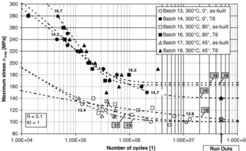
oritantations and compared to the die cast equivalent [49]. ... 50 Figure 20: Fatigue performance of SLM AlSi10Mg samples in their as-built
and heat treated (T6) conditions. The samples were built in various
orientations (0º, 45º, and 90º) with respect the build plate [18]. ... 52 Figure 21: Mapping the various experiments conducted in this thesis. ... 60 Figure 22: Schematic presentation for the fusion lines experiments (a) single
and (b) overlapping. ... 61 Figure 23: Selective laser melting of AlSi10Mg (a) in process, (b) process
completed, and (c) test cubes on the platform. ... 64 Figure 24: Laser spatter shown as darker particles surrounding the cubes being
built. ... 68 Figure 25: Schematic presentation for the top view of the processing chamber
in the SLM machine showing gas circulation. ... 70 Figure 26: Planes of a cubic sample with layers in the XY-plane stacking up in
the building direction (Z-axis). ... 72 Figure 27: T6 heat treatment investigations study plan. ... 73
XVI
Figure 28: Samples for nanoindentation. ... 74
Figure 29: NanotestTM indenter tip-sample setup. ... 76
Figure 30: Tensile test sample. ... 77
Figure 31: Compression test specimen. ... 78
Figure 32: Fatigue test samples. ... 79
Figure 33: Fatigue test specimen. ... 80
Figure 34: Thinning of fusion line with increasing the scan speed. ... 82
Figure 35: Reduction in HAZ thickness with increasing scan speed. ... 83
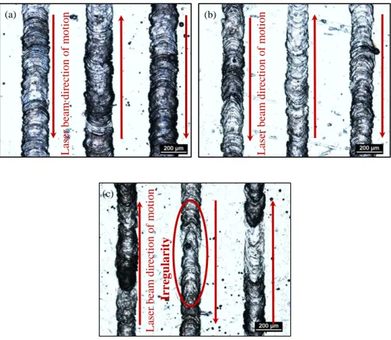
Figure 36: Irregularities in fusion lines using 750, 1000, 1250, and 1500 mm/s. ... 84
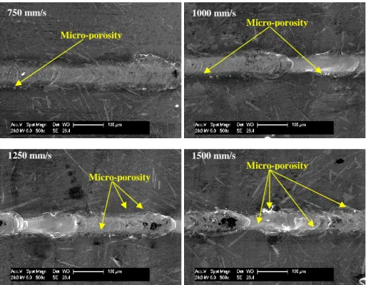
Figure 37: Fusion lines produced using different scan speeds showing evidence of micro-porosity. ... 85
Figure 38: Cross-sectional view of the polished fusion lines at different scan speeds. ... 86
Figure 39: Effect of scan speed on width and depth of penetration of the fusion lines (with error bars showing standard error). ... 87
Figure 40: Overlap of fusion lines with 50 µm hatch spacing using (a) 250, (b) 500, and (c) 750 mm/s. ... 89
Figure 41: Lack of overlap between fusion lines at 750 mm/s and 150 µm hatch spacing. ... 89
Figure 42: Transverse view showing overlap of fusion lines processed using a speed of 500 mm/s and a hatch spacing of 50 µm. ... 90
Figure 43: Single tracks of AlSi10Mg from 40 µm thick layers at (a) 250, (b) 500, and (c) 750 mm/s. ... 91
XVII
Figure 44: Cross-sectioned single tracks processed from a 40 µm thick powder layer at (a) 250 mm/s, (b) 500 mm/s, and (c) 750 mm/s. ... 92 Figure 45: Single tracks of selective laser melted AlSi10Mg (250 mm/s and
400 µm layer thickness). ... 95 Figure 46: Single tracks of selective laser melted AlSi10Mg (500 mm/s and
400 µm layer thickness). ... 95 Figure 47: Single tracks of selective laser melted AlSi10Mg (750 mm/s and
400 µm layer thickness). ... 95 Figure 48: Cross-sections of single tracks formed using a layer thickness of 400 µm with a 250 mm/s scan speed... 97 Figure 49: Different forms of single tracks processed at 500 mm/s using a 400
µm layer thickness (a) free circular cylinder and (b) segmental cylinder. 98 Figure 50: Different forms of single tracks processed at 750 mm/s using a 400
µm layer thickness (a) free circular cylinder and (b) segmental cylinder. 98 Figure 51: Topography of a 400 µm thick single layer of selective laser melted
AlSi10Mg using 750 mm/s scan speed and 50 µm hatch spacing. ... 101 Figure 52: Cross-sectional view of a polished single layer with balling on the
surface with the inset showing the balling region after etching. ... 101 Figure 53: A satellite on top of a single track processed from a 40 µm thick
powder layer using 250 mm/s (a) low and (b) high magnification, and (c) showing cross-sectioned as-received powder. ... 102 Figure 54: Topography of a 40 µm thick single layer of selective laser melted
XVIII
Figure 55: Topography of a 40 µm thick single layer of selective laser melted AlSi10Mg using 500 mm/s scan speed and 50 µm hatch spacing with arrows pointing to small satellites. ... 104 Figure 56: Topography of a 40 µm thick single layer of selective laser melted
AlSi10Mg using 750 mm/s scan speed and 50 µm hatch spacing with arrows pointing to larger satellites and gaps or voids in the layer. ... 104 Figure 57: Topography of a 400 µm thick single layer of selective laser melted
AlSi10Mg using 250 mm/s scan speed and 50 µm hatch spacing. ... 106 Figure 58: Topography of a 400 µm thick single layer of selective laser melted
AlSi10Mg using 500 mm/s scan speed and 50 µm hatch spacing. ... 106 Figure 59: Topography of a 400 µm thick single layer of selective laser melted
AlSi10Mg using 750 mm/s scan speed and 50 µm hatch spacing. ... 107 Figure 60: A single layer of 40 µm thick selective laser melted AlSi10Mg
formed using a hatch spacing of 50 µm and a scan speed of (a) 250 mm/s, (b) 500 mm/s, and (c) 750 mm/s. ... 108 Figure 61: A 400 µm thick single layer of selective laser melted AlSi10Mg
(250 mm/s scan speed and 50 µm hatch spacing). ... 109 Figure 62: Single layers of selective laser melted AlSi10Mg (a-d: 500 mm/s)
and (e-g: 750 mm/s) using 50 µm hatch spacing and 400 µm layer
thickness. ... 111 Figure 63: Particle size distribution of AlSi10Mg powder supplied by LPW
technology with the inset showing the morphology of the powder. ... 118 Figure 64: Cross-sectioned AlSi10Mg powder supplied by LPW Technology
showing evidence of inherent porosity at (a) low and (b) high
XIX
Figure 65: Cellular-dendritic microstructure in the cross-sectioned AlSi10Mg powder. ... 119 Figure 66: Low magnification images for the surface topography of AlSi10Mg
test cubes produced by SLM using different hatch spacing values (a) 50 µm, (b) 100 µm, (c) 150 µm, (d) 200 µm, and (e) 250 µm. ... 120 Figure 67: High magnification images for the surface topography of AlSi10Mg
test cubes produced by SLM using different hatch spacing values (a) 50 µm, (b) 100 µm, (c) 150 µm, (d) 200 µm, and (e) 250 µm. ... 121 Figure 68: Effect of changing the hatch spacing on the relative density
represented by the pore area fraction on micrographs determined using ImageJ. ... 122 Figure 69: Evolution of pores with scan speed (a) 250, (b) 500, (c) 750, and (d)
1000 mm/s. ... 125 Figure 70: Extensive presence of metallurgical pores only at scan speeds below 250 mm/s (a) 100 mm/s, (b) 150 mm/s, and (c) 200 mm/s. ... 125 Figure 71: The influence of energy density variation on a sample's degree of
porosity. ... 128 Figure 72: Balling increases with the increase in scan speed (a) 250, (b) 500,
(c) 750, and (d) 1000 mm/s. ... 130 Figure 73: Porosity evolution in samples processed using different
combinations of scan speeds and scan strategies. ... 132 Figure 74: Influence of scan strategy on relative density for each of the scan
speeds investigated 500 mm/s, 750 mm/s, and 1000 mm/s... 133 Figure 75: Microstructure of etched samples (HS 50 µm, SS 500 mm/s, and
XX
keyhole pore where the pore (not shown) is below the coarse
microstructure, and (c) keyhole pore enclosing non-molten powders. ... 134 Figure 76: Keyhole pore enclosing non-molten powders. ... 135 Figure 77: Microstructure of the melt pools demonstrating (a) cell orientation,
(b) morphology, and (c) grain size distribution. ... 136 Figure 78: Microstructure of an AlSi10Mg sample produced by SLM using the
pre-melt scan strategy at 500 mm/s. ... 137 Figure 79: Morphology of (a) fresh powder and (b) laser spatter. ... 139 Figure 80: Elongated and irregular particle morphology in the LPW powder.
... 140 Figure 81: Particles in the TLS powder were mostly spherical with observed
satellites. ... 141 Figure 82: Microstructure of the cross-sectioned powder from batch (a) LPW
and (b) TLS. ... 142 Figure 83: Particle size distribution for AlSi10Mg powders supplied by LPW
and TLS. ... 144 Figure 84: Relative density of SLM samples processed using different scan
strategies and powders with error bars representing the standard error. . 146 Figure 85: Effect of gas circulation on the relative density of SLM Al parts
showing inter-build variability. ... 148 Figure 86: Summary of the study and findings. ... 150 Figure 87: Microstructure of a single track processed using 250 mm/s revealed
using Keller's reagent at (a) low and (b) high magnification. ... 155 Figure 88: Microstructure of a single track processed using 500 mm/s revealed
XXI
Figure 89: Mapping the chemical composition of Si in (a) a scan track
processed from a 40 µm powder layer at 250 mm/s scan speed with Si in (b) presented by the green colour. ... 158 Figure 90: Microstructure of overlapping melt pools in a single layer processed
at 250 mm/s revealed by Keller's reagent. ... 159 Figure 91: Microstructure of overlapping melt pools in a single layer processed
at 500 mm/s revealed by Keller's reagent. ... 160 Figure 92: Morphology of the top surface of an AlSi10Mg part produced by
SLM as seen by (a) secondary electrons detector SE and (b) backscatter electrons detector BSE (surface perpendicular to the building direction). ... 161 Figure 93: Profile measurement for the surface of an AlSi10Mg SLM part. . 162 Figure 94: XRD pattern for AlSi10Mg samples processed by SLM. ... 163 Figure 95: The (a) (110), (b) (100), and (c) (111) pole figures with (d) unit cell
demonstrating the mapped planes. Note the build direction (BD), the scanning direction (SD), and the transverse direction (TD). ... 165 Figure 96: Microstructure of as-built AlSi10Mg sample produced by SLM
showing XY, XZ, and YZ planes with lower magnification (top) and higher magnification (bottom)... 166 Figure 97: Microstructure of AlSi10Mg part processed by SLM (a) XY-plane
and (b) YZ-plane. ... 168 Figure 98: Coarser grains observed at the melt pool boundary in the (a)
XXII
Figure 99: Microstructure of (a) as-built sample XZ plane, (b) as-built sample XY plane, and (c) EDX composition map for Si in the as built sample XY plane. ... 169 Figure 100: Microstructure of SLM samples (a) XY plane after 1 hr SHT, (b)
XZ plane after 1 hr SHT and 12 hrs AA , (c) XZ plane after 4 hrs SHT, (d) XZ plane after 4 hrs SHT and 6 hrs AA, and (e) higher magnification image of XZ plane after 1 hr SHT and 6 hrs AA showing the morphology of Si particles. ... 172 Figure 101: Higher magnification SEM image clearly showing inter-dendritic
Si around the α-Al boundaries in the as-built sample. ... 173 Figure 102: Particles analysis showing change in (a) average particle size and
(b) particle density with heat treatment duration with error bars
representing the standard error. ... 174 Figure 103: An illustrative example for loading and unloading in a
nanoindentation test (a) schematic presentation for an indentation [137] and (b) load-depth curve... 179 Figure 104: Nano-hardness profile of a line positioned at half the maximum
height of a scan track spanning across both the laser irradiated material and the as-cast material. ... 180 Figure 105: The nano-hardness profile across the AlSi10Mg scan track (a)
including the cast substrate and (b) excluding the cast-substrate. The array of indentations from which the nano-hardness map was retireved is shown in (c). ... 183 Figure 106: The array of indentations on (a) a series of overlapping melt pools
XXIII
Figure 107: SEM micrographs showing nano-indents and corresponding chemical compositions within (a) the laser irradiated material (a) and at (b), (c), and (d) various points within the cast substrate. ... 185 Figure 108: An array of indentations across layers in a part fabricated using a
single scan strategy showing (a) the microstructure and (b) the
corresponding nano-hardness map. ... 187 Figure 109: An array of indentations across layers in a part fabricated using a
pre-melt scan strategy showing (a) the microstructure and (b) the
corresponding nano-hardness map. ... 187 Figure 110: (a) Coarsened microstructure in the vicinity of a keyhole pore
(towards the top) in a sample processed using a unidirectional scan
strategy alongside (b) the corresponding nano-hardness profile. ... 188 Figure 111: (a) Coarsened microstructure in the vicinity of a keyhole pore
(towards the bottom) in a sample processed using a pre-melt scan strategy alongside (b) the corresponding nano-hardness profile. ... 188 Figure 112: Nano-hardness map demonstrating the property profile within (a)
as-built SLM AlSi10Mg and (b) heat-treated SLM AlSi10Mg, as well as examples of the nano-indents on the tested surfaces (c) as-built SLM material and (d) heat-treated SLM material. ... 190 Figure 113: Microstructure of the SLM AlSi10Mg (a) as-built and (b) heat
treated, and (c) high magnification image for the as-built microstructure revealing the inter-dendritic Si within the α-Al matrix. ... 192 Figure 114: Evolution of micro-hardness with heat treatment procedure with
XXIV
Figure 115: Engineering tensile stress-strain curves comparing the behaviour of SLM AlSi10Mg with and without heat treatment. ... 198 Figure 116: The overall fracture surface of a tensile sample with the origin of
failure highlighted along with the direction of crack propagation pointed out by arrows. ... 199 Figure 117: Cross-sectional view of the fracture surface of a tensile sample
demonstrating crack propagation along melt pool boundaries. ... 199 Figure 118: Fracture surface of SLM AlSi10Mg (a) as-built and (b)
heat-treated T6. ... 201 Figure 119: Cross-sectioned fracture surface of tensile samples: (a) as-built
material with (b) the corresponding representative chemical composition mapping and (c) heat-treated material with the corresponding chemical composition mapped in (d). ... 202 Figure 120: The compressive behaviour of SLM AlSi10Mg with and without
heat treatment (average of three results per condition). The standard error is highlighted in yellow. The inset shows samples before and after testing. ... 205 Figure 121: Surface morphology of the sides of (a) an as-built fatigue sample
and (b) a sample with machined surface (surface parallel to the building direction). ... 208 Figure 122: Effect of machining on the fatigue performance of SLM
AlSi10Mg. ... 209 Figure 123: Effect of heat treatment on the fatigue behaviour of SLM
XXV
Figure 124: Effect of heat treatment followed by machining on the fatigue behaviour of SLM AlSi10Mg... 212 Figure 125: S-N curves superimposed for all the investigated conditions,
namely, (1) as-built, (2) heat treated, (3) machined, and (4) heat-treated & machined. ... 214 Figure 126: Fracture surface of an as-built sample tested at a maximum stress
of 94 MPa. ... 217 Figure 127: Zones of fatigue fracture in an as-built sample loaded by a
maximum stress of 94 MPa (a nominal stress of 52 MPa and an amplitude of 42 MPa). ... 218 Figure 128: Zones of fatigue fracture in an as-built sample loaded by a
maximum stress of 157 MPa (a nominal stress of 86 MPa and an
amplitude of 71 MPa). ... 219 Figure 129: Zones of fatigue fracture in an as-built sample loaded by a
maximum stress of 220 MPa (a nominal stress of 120 MPa and an
amplitude of 99 MPa). ... 219 Figure 130: Fatigue fracture surface cross-section. ... 220 Figure 131: Fatigue cracks propagating through the fatigue cracked region. 221 Figure 132: Fatigue striations on the fracture surface of an as-built sample. . 222 Figure 133: Cleavage fans and lines on the fracture surface of as-built samples
tested at high stress levels (120 MPa nominal stress). ... 223 Figure 134: The scan tracks building up the sample using the checkerboard
scan strategy clearly seen on the fracture surface of the as-built fatigue sample (pointed out by the arrows). ... 224
XXVI
Figure 135: Foreign particle on the fracture surface of the as-built fatigue test sample. ... 225 Figure 136: Mapping the chemical composition at the foreign particle on the
fatigue fracture surface. ... 225 Figure 137: Fracture surface of a fatigue test specimen with machined surface
showing failure to originate at a sub-surface defect. ... 227 Figure 138: Sub-surface pore that was revealed after machining the sample. 227 Figure 139: High magnification images for the fracture surfaces of as-built
XXVII LIST OF TABLES
Table 1: Comparison of properties of SLM candidate materials. ... 7 Table 2: Summary of the experimental plan for the single tracks
experiments. ... 62 Table 3: Processing parameters combinations used in the hatch spacing
study. ... 65 Table 4: Combinations of processing parameters used in the scan speed
study. ... 65 Table 5: Scanning strategies variable parameters ... 66 Table 6: Processing parameters (set 1) using Renishaw AM250 to produce near fully dense parts. ... 71 Table 7: Processing parameters (set 2) using Renishaw AM250 to produce near fully dense parts ... 75 Table 8: Geometrical dimensions of AlSi10Mg single tracks. ... 93 Table 9: Chemical composition of LPW AlSi10Mg powders in relative
weight%. ... 118 Table 10: Relative density values (%) at different combinations of hatch
spacing and scan speed... 123 Table 11: Chemical composition of powders and bulk sample in relative
weight %. ... 138 Table 12: Comparing chemical composition of powders from different
suppliers - in weight %. ... 143 Table 13: Comparing the micro-hardness of SLM AlSi10Mg with and
XXVIII Table 14: Tensile properties of SLM AlSi10Mg developed in this study
compared to results from the literature for SLM and die cast
counterparts. ... 203 Table 15: The compressive properties of SLM AlSi10Mg before and after
heat treatment. ... 206 Table 16: The evolution of nano-hardness from a single track to a bulk
sample. ... 229 Table 17: Summary of the effect of a conventional T6 heat treatment on
1
CHAPTER (1):
Introduction
Various industrial sectors are now benefiting from the possibility of fabricating geometrically complex structures using additive manufacturing (AM) technologies for their several advantages, such as light-weighting and added functionality. AM also has the potential to fulfil demands for reducing the cost and time from design to manufacturing through saving on raw materials and cutting down a series of production processes and replacing them by a one step process. AM processes are sometimes referred to as Layered Manufacturing in reference to the nature of the process where a part is fabricated layer-by-layer from three-dimensional (3D) data [1]. AM is a commonly used term in the industry but the process is also known as autofab (autofabrication), freedom fabrication, layer-based manufacturing, stereolithography, or 3D printing [2]. These processes can be used for the production of prototypes or tools; however the term AM should only be used for the manufacture of end products. Originally, AM was used with polymeric materials and development of powder-bed based AM technology for metals resulted in Selective Laser Melting (SLM). The metallic-based AM processes also include Direct Metal Laser Sintering (DMLS) and Electron Beam Melting (EBM) [3-7].
Modern layered-manufacturing dates back to the mid-1980s and started to flourish during the late 1980s and early 1990s [8, 9]. 1994, however, is the year that marks the onset of an exponential increase in demand for layered-manufacturing machines [9] and only recently it has been considered part of a new industrial revolution [10]. Selective laser melting is gaining wide
2
popularity at the industrial and research levels [8, 11] as it fulfils the aim of manufacturers in shortening supply chains and lead times [12] and raising the level of automation in manufacturing along with the rates of production [13] via substitiuting a series of manufacturing process by one process. AM also promotes the possibility of producing cost-effective customised products [10, 14]. As the credibility of AM increases, its impact is expected to affect global business [9]. Already parts produced using AM are widely used in various fields, such as the medical [15], automotive, and aerospace industries [10]. Although AM has several advantages in terms of saving resources and allowing a high degree of fabrication freedom to manufacture complex and intricate parts, it cannot be generalised that AM would be suitable for businesses regardless of their needs and sizes. Conner et al. [14] developed a map for AM processes and their feasibility. By means of this map, business leaders can determine, based on the complexity, customisation, and production volume, whether AM is a suitable alternate to conventional manufacturing. The metallic AM systems are categorised based on the system used to supply the material to be processed. There are three main types, namely, powder-bed systems, powder-feed systems, and wire-feed systems. Also, the heating source deployed is used to differentiate between the various processes; the most popular are electron beam and laser beam [9]. The technology of interest in the current study is SLM, which is a powder-bed process with a laser beam as the heat source.
The use of lasers in manufacturing is very common nowadays. Lasers gained consideration as machine tools and in the industrial processing of materials during the 1970s. Most importantly, the transition of laser processing from
3
laboratories to industry happened over the 1990s. The 2000s saw laser systems become cheaper, smaller, and more flexible [16].
1.1. Selective laser melting (SLM)
SLM can fabricate components from loose powder that can not only have a comparable physical shape to conventionally manufactured components but also similar properties [17]. Generally, powder-bed processes offer geometrical flexibility in manufacturing industrial parts [18]. SLM can produce complex and intricate parts that would require a series of manufacturing processes if made by conventional techniques, consuming excess material (i.e. wastage), time and energy [17, 19-22]. In some cases it is even possible to manufacture parts using SLM that cannot be achieved using any conventional manufacturing method [10, 17, 23]. In addition, the process has the potential to save cost and time [17, 19-21] by saving costs on raw materials volume for being resource-efficient and shortening the time from design to manufacture through cutting down lead times in multi-process fabrication. Moreover, SLM promotes the possibility of producing large customized products [10] and it is a promising technique to manufacture functionally graded multi-material parts [20, 24].
The interest in SLM is partly motivated by the aim of finding a cleaner and more resource-efficient manufacturing process. In some cases, SLM can have outstanding ecological indicators since it saves resources as wastage has the potential of approaching zero [25] because the leftover powder from one SLM process is usually sieved and goes back into the system for re-use. The effect of using recycled powder was investigated by Ardila et al. [26]. They conducted
4
their experiments using IN718 powder and reported a material use efficiency of 95%. Using AM rather than conventional manufacturing can also reduce the carbon footprint [23]. Another advantage is design optimization since the technique allows complex parts to be created at little or no extra cost, enabling light-weight structures. Drastic weight reduction can be achieved by several methods, such as topology optimisation [27-29] or replacing a bulk of solid material with latticed structures [30-36]. Besides weight-reduction, lattice structures have wide applications in fields such as thermal insulation, shock absorption, acoustic absorptions, as well as being widely used in biomedical implants [37]. In brief, SLM promotes “design for performance” rather than “design for manufacturing” [25].
1.2. Aluminium alloys in industry
Properties of Al alloys are considered outstanding since they have low density (2.7 gm/cm3), high strength [38], adequate hardenability [39], good corrosion resistance [40-42], and excellent weldability [39]. As the demand for technologically complex and ecologically sustainable products increases, opportunities for Al in industry are expected to further flourish. Al is suitable for numerous applications, such as automobiles [43], food and beverage packaging, building construction, electricity transmission, transportation infrastructure, defence, aerospace, and machinery and tools production [40, 42].
Al-Si-Mg alloys are widely used in the automotive industry [44]. They are hardened by Mg2Si so they are excellent for casting and welding in addition to
5
industries [45]. Generally, Al alloys are favoured in the automotive industry for their light-weight since each 10% reduction in weight is equivalent to 5.5% reduction in fuel consumption [41]. Al-Si-Mg alloys such as (12% Si- 2.5% Ni – 1% Cu – 1% Mg) are used in manufacturing diesel engines and (9.5%Si – 3% Cu – 1% Mg) alloys are used in manufacturing pistons for automotive internal combustion engines [45]. The alloy Al7075 is extensively used by aircraft manufacturers [41]. Al alloy 296 is used for aircraft fittings and pumps, whereas 356 is used in engine blocks, transmissions, and wheels [42]. Aluminium is a superior candidate in applications where specific strength and stiffness are design considerations.
1.3. Aluminium alloys and selective laser melting
As much as AM processes are finding their way into commercialisation at a fast rate, not many materials are yet processable by SLM [8, 46]. This is due to the different physical properties of the material. The current research interest in SLM mainly focussed on titanium [47, 48], high speed steels [19], and nickel super alloys [9, 49], although a few other commercial alloys are being used in AM, such as tool steels (H13 and Cermets) and some refractory alloys (MoRe, Ta-W, CoCr, and alumina) [9]. This is because these SLM candidate materials process relatively easily compared to others. Also, the fact that SLM has the potential of producing no wastage [25] is appealing to manufacturers using expensive metals for savings on materials cost [50]. Since the interest of this study is mainly to process Al alloys using SLM; particularly the AlSi10Mg alloy, it is important to highlight the challenges facing Al alloys.
6 The challenges in Al SLM
Al alloy powders are inherently light (low density) with poor flowability and high reflectivity (owing to the high density of free electrons [16]), along with high thermal conductivity relative to other materials, as can be seen in the chart in Figure 1. When compared to other SLM candidate materials, such as titanium and stainless steels, as shown in Table 1; the difference in thermal conductivity and flowability indicates that Al alloys are expected to face challenges in the process of SLM. The values for the flowability of metal powders in Table 1 are experimental values determined at the Additive Manufacturing and 3D printing laboratories in the University of Nottingham [51] using a Hall flowmeter after ASTM standard B213 [52]. The “no flow” term in the table corresponds to the flowability of the AlSi10Mg powder and indicates extremely poor flowability. Since the SLM process involves successive deposition of layers of powder, it is important for the powder used to have good flowability; otherwise the deposited layer will not be uniform, leading to the formation of defects. The high thermal conductivity and reflectivity of Al alloys means that high laser power is required for melting to overcome the poor absorption and rapid heat dissipation [42], although the rapid heat dissipation is more of an issue for solid Al substrate than for the Al powder. Laser absorption by Al is poor because it is bound by outer electrons with less energy levels compared to other elements [16, 41]. Moreover, Al alloys are highly susceptible to oxidation, which promotes porosity [4, 16, 53]. Also, the low viscosity of molten Al is a contributor to porosity [16]. One of the major challenges in producing Al alloys parts using SLM is minimizing
7
porosity and several studies have investigated the effect of processing parameters on porosity [25, 53, 54].
Figure 1: Thermal conductivity of various materials [16].
Table 1: Comparison of properties of SLM candidate materials.
SLM Candidate Material Flowability (s / 50 gm)1 Thermal Conductivity (W/m K) Reflectivity (%) Ti64 47 6.7 [55] 53-59 [56] 316L stainless steel 14.6 21.4 [57] 60 [58] Al6061 77 172 [57] 91[59] AlSi10Mg No flow 146 [57] 91 [59]
1.4. The significance and novelty of this research
Although the best candidate materials for SLM are nickel-based alloys and titanium alloys, as claimed by Osakada and Shomi [3], paving the way for SLM to become a substitution to conventional subtractive manufacturing
1
Experimental values for flowability were determined using Hall flow rate standard test method [52] Standard Test Methods for Flow Rate of Metal Powders Using the Hall Flowmeter Funnel. West Conshohocken: ASTM International; 2013. All powder materials were supplied by LPW Technology, UK.
8
requires widening the range of usable materials. Owing to its outstanding properties, Al is endorsed for use in a vast number of applications, whether conventional or modern [60]. The possibility of manufacturing parts using SLM from Al alloys will open up further opportunities for the alloy in the industry. This will include not only the parts that are conventionally manufactured but even parts that require machining, where the alloy is difficult to machine, such as the case with AlSi10Mg due to limitations imposed by the presence of the Si hard phase. Understanding the properties of parts produced using SLM from Al alloys, both microstructural and mechanical, is expected to expand the use of these alloys if found to have properties different from conventionally manufactured and more favoured.
The importance of this research lies within the need to develop suitable criteria to be able to successfully manufacture near fully dense AlSi10Mg parts using SLM since studies available so far report parts to suffer from high degrees of porosity. To do so, the challenges facing processing AlSi10Mg have to be resolved. Since the crucial problem arising from all these challenges is the parts’ porosity, then the reasons behind the formation of pores in AlSi10Mg parts and their formation mechanisms need to be defined. Based on their definition, the sources of porosity could be traced and rectified to either eliminate or minimize it. A hierarchal study to trace the means of porosity formation and cut them at the source is novel. Furthermore, there is insufficient data on the mechanical behaviour of SLM Al alloys and the effect of heat treatments, which this investigation plans to provide.
9 1.5. Thesis aim, objectives, and methodologies
This research aims to construct a comprehensive understanding of the SLM process considering its various aspects to produce near fully dense samples and the interrelation between the microstructure of the material and its mechanical performance. To achieve this aim, the research is divided into four parts with individual objectives laid out in Figure 2.
10
The thesis objectives are:
1. Determining the melting and solidification behaviour of Al alloys when irradiated with a laser beam during SLM, the formation of single tracks and their stability, and the production of a single layer from overlapping scan tracks.
2. Defining the reasons behind the problem of porosity in Al parts processed by SLM and tackling them to produce dense parts
3. Evaluating the microstructural features of SLM Al tracks, layers, and parts. This incorporates the microstructure of the samples as-built (right out of the machine) and the microstructural response to heat treatment. 4. Assessing the mechanical performance of the SLM Al parts in terms of
nano, micro, and macro behaviours.
5. Relating the processing parameters to the microstructure, properties, and performance of the SLM Al parts.
The methodology in this study will be to start from the powders used in SLM covering the various process aspects until producing near fully dense parts and then characterising them. The topography and cross-sections of single tracks and layers formed in SLM using a range of scan speeds and layer thicknesses will be studied to achieve the first objective. A parametric study focussing on the main processing parameters, such as hatch spacing, scan speed, scan strategy, powder quality, and gas flow rate within the processing chamber, will be conducted to select the best combination of processing parameters to produce near fully dense parts, i.e. material qualification (objective 2). It has previously been reported that SLM produces characteristic microstructure [47, 48] that is different from conventionally processed materials for various alloys.
11
Consequently, it is important to examine this for Al alloys through microstructural characterisation of the near fully dense parts and determining the response of the SLM microstructure to heat treatments (objective 3). Furthermore, the near fully dense samples will be subjected to various types of mechanical loading in order to fulfil objective number 4 and measure the local (nano-hardness) and global (micro-hardness, tension, compression, fatigue) mechanical properties. Lastly, the findings from the abovementioned studies will be tied in together to draw up the big picture and achieve the aim of this investigation by connecting the processing method, produced microstructure, and developed mechanical performance.
The benefits from the outcomes of this study will not be limited to understanding the properties of SLM Al alloys. They will be important for studies concerned with the production of lattice structures to be able to have more solid predictions and understanding of their behaviours. Research concerned with the use of lattice structures [22, 37] to replace solid material and topology optimisation [27, 28, 30, 31] as means for light-weighting is gaining wide attention nowadays and a comprehensive understanding of the SLM process and its outcomes is a great asset for such applications to flourish. Light-weighting using these two approaches in SLM is currently commonplace because they aid in saving materials and resources.
1.6. Thesis outline/structure
In order to build up a comprehensive understanding of the SLM process for Aluminium alloys, this thesis will present the various interrelated aspects of the process in the sequence shown in Figure 3.
12
Figure 3: Thesis outline/structure.
The first, current, chapter of this thesis is basically an introduction to additive manufacturing and the interest in this research field. In addition, the aim and objectives of the study are laid out. This chapter also provides background information and clarifies the context for this research.
The second chapter presents a summary of what has already been done in the area of interest (literature review) and where the current study stands and how it fits in. In addition, this chapter sheds the light on the areas that were not fulfilled in the literature but will be resolved in the current study. It also includes some basic definitions and information regarding the SLM process and the material under investigation.
The third chapter describes the materials and methods used in conducting the research, i.e. details of the experimental work carried out over the course of this investigation.
Chapter (8): Conclusions & recommendations for future work
Chapter (7): Mechanical characterisation of SLM AlSi10Mg
Chapter (6): Microstructural characterisation of SLM AlSi10Mg
Chapter (5): Parametric study to produce near fully dense parts
Chapter (4): Single tracks & layers in SLM
Chapter (3): Materials & methods
Chapter (2): Literature review
13
Chapters (4) through to (7) present the results achieved over the course of the investigation. The fourth chapter covers the findings achieved from a study on the formation of single tracks and layers in selective laser melting. The fifth chapter includes the parametric study to produce near fully dense AlSi10Mg parts. Moving on from success in producing near fully dense AlSi10Mg parts using SLM in chapter (5), the sixth chapter focusses on the microstructural characterisation of selectively laser melted AlSi10Mg. This chapter also comprises a study on the effect of a conventional T6 heat treatment on the microstructure of the SLM material. The seventh chapter, which is the last chapter covering the results of this thesis, focusses on the mechanical characterisation of selectively laser melted AlSi10Mg. A number of mechanical properties are considered in this chapter, such as nano-hardness, micro-hardness, tensile behaviour, compressive properties, and fatigue performance. The thesis conclusions that highlights the key findings from this study are then summarised in chapter (8) followed by some recommendations for future work. This chapter also puts the research findings in context and highlights their contribution to knowledge in the academic and industrial contexts.
14
CHAPTER (2):
Literature Review
The scope of this chapter is to provide a summary of what was found in the literature regarding research on the various aspects of selective laser melting of aluminium alloys, starting from powder used in SLM to characterising the near fully dense parts. Towards the end of the chapter, the gaps in the literature in the area of selective laser melting of aluminium alloys that this thesis aims at approaching are pointed out.
2.1. Aluminium and its alloys
The metal Aluminium was initially named Alumine as early as 1671. This nomenclature was for the base of alum that was originally used by the Romans and Greeks. The name Aluminum was first used in 1807, which was later on changed to Aluminium. The International Union of Pure and Applied Chemistry (IUPAC) adopted the name Aluminium in order to conform with the “ium” ending of most elements, so Aluminium became the international
standard [40]. This spelling was accepted in the United States of America until 1925 when the American Chemical Society decided to revert back to Aluminum [16, 40].
Aluminium is heavily consumed compared to all other non-ferrous metals. The worldwide annual consumption of aluminium is 24 million tons, 18 million tons of which is extracted from ore, i.e. primary Aluminium, and the rest is derived from scrap metal processing, i.e. secondary Aluminium. Aluminium is
15
known for its very high chemical affinity for oxygen, which is why it cannot be found in nature as a metal but is always found in the form of alumina or other combined oxide form [40]. Aluminium is ranked the second most plentiful metallic element on earth as it represents 8 % of the earth’s crust, followed by Iron (5 %), Mg (2 %), Zn, and Sn (0.004 %) [40, 42].
From a chemistry perspective, Al is an element in the third group of the periodic table of elements; its atomic number is 13 and atomic weight is 26.98 based on oxygen [40, 41, 61]. It has no natural isotopes; however artificial isotopes can be produced and are radioactive [40, 61]. From a metallurgical perspective, Al has a face-centred cubic (FCC) crystal structure with a co-ordination number of 12 and an atomic packing factor of 0.74 [40, 41]. The length of the unit lattice cube contracts by decreasing the purity of the metal due to the formation of impurity segregations [40, 61]. Deformation in Al alloys happens by crystallographic slip on the {111} planes in the <110> directions, which means there are 12 slip systems, resulting in high ductility [38, 41]. The melting temperature of Al is 660°C and its boiling temperature is 2520°C. Its mean specific heat for temperatures between 0 °C and 100 °C is 917 J.kg-1.K-1 [41].
Al powders can be found in a wide range of particle sizes ranging between 0.015 μm and 17,000 μm, as well as different shapes such as spheres, thin flakes, or irregular powders. The powders are classified according to certain parameters such as apparent density, specific surface (surface area per unit weight), and oxide content [61]. There are various types of powders, such as: air atomized, spherical atomized, water atomized, acicular, grained, granulated,
16
ultra-fine, fibres, flakes, flitter, chopped and balled, shot particles, cut foil, brittle alloy, and machined particles [62].
Physical metallurgy of Aluminium and its alloys
Pure Al has the lowest strength compared to its alloys, which is why Al is always used in the form of an alloy [38] despite the success of the studies on strengthening pure Al [62-64]. Pure Al is commonly used in electrical applications, such as conductor cables. The major alloying elements used are Cu, Mg, and Si as strengthening elements, Mn and Sb to enhance corrosion resistance, Ti and Cr for grain refinement, Ni for boosting the thermal strength, and Co, Fe, and Bi to improve machinability [38, 41, 42].
The addition of Si to Al to produce cast alloys improves several properties such as increasing the fluidity and reducing solidification contraction [16, 41]. The phase diagram of the Al-Si alloy system (the alloy of interest in this research) in Figure 4 shows that the relationship between the two components has a eutectic reaction taking place at 12.6 % Si and a temperature of 577 °C [38, 41, 42].
17
It is difficult to machine Al-Si alloys because of the presence of the hard phase Si [41]. The addition of Mg to the Al-Si alloys strengthens the alloy by promoting the formation of Mg2Si precipitates and yields the alloy
heat-treatable [16, 41]. Mg is also considered to be the most effective strengthening alloying element because of its high solubility [41]. Si and Mg are the main alloying elements for Al because they have atomic structures that are almost identical to Al, however, the crystal structures are different [38]. Si and Mg are the direct neighbours of Al in the periodic table of elements with an atomic number of 12 for Mg, 14 for Si, and 13 for Al. The crystal structures on the other hand are distinct since Al has FCC crystal structure, Si has a diamond type cubic crystal structure and Mg has a hexagonal close-packed structure. Heat-treatable Al-Si-Mg alloys are usually treated by tempering (precipitation hardening T6) in a specific sequence that is [38, 41, 42]:
a) Solution heat treatment (SHT): at this stage the material is heated to a high temperature in the single phase region, not exceeding the solidus temperature (below the eutectic temperature) to avoid overheating or localized melting.
b) Quenching: the material is then quenched to room temperature, i.e. rapidly cooled to room temperature to obtain a super saturated solid solution (SSSS). Usually water is used for quenching large objects but for small and/or thin sections this might introduce residual stresses. The alternative then for a slower quenching rate is to use hot or boiling water or even air-cooling.
c) Ageing or precipitation hardening: Ageing could be either natural or artificial. The material is maintained at an elevated designated temperature(s) for a duration of time to allow the decomposition of the SSSS into finely
18
dispersed precipitates. Nucleation occurs at the Guinier–Preston (GP) zones or dislocations [40]. For a more pronounced ageing effect, sometimes the metal is cold worked before ageing to increase the dislocation sites (density of dislocations).
2.2. Aluminium powder for SLM
2.2.1. Properties of powder
Powders used in SLM are produced either by gas atomisation or plasma rotating electrode (plasma atomisation) with the former being more common [65]. The quality of the powder used is one of the SLM process variables [20]. Since the process constitutes successive deposition of uniform layers of powder, it requires the powder to have particular properties to enhance its flowability and packing density; these are controlled by the powder morphology and size distribution. In contrast to irregular particles, spherical particles mean better flowability [66] and higher packing density; two characteristic features that are pre-requisites in SLM [21, 67]. The same alloy can have different morphological properties based on the suppliers and how well they adhere to the standards. In addition, the chemical composition of the powder also affects the process. For instance, the presence of gas phase in the starting powder significantly supresses densification [68]. Li et al. [21] compared the use of water-atomised 316L stainless steel to the gas-atomised powder and showed the superiority of the gas-atomised powder due to the lower oxygen content and higher packing density. The role of powder specifications has also been studied by Kempen et al. [54] who tested processing with AlSi10Mg with different morphological and chemical
19
properties. Their results confirmed that the choice of powder properties is critical as it affects the quality of the produced parts, in terms of porosity either due to chemical composition, morphology, or moisture. Upon irradiating the powders with a laser beam, there exists an energy balance between conductivity (K) and absorptivity (A). The absorptivity or reflectivity of the powder depends not only on the physiochemical properties of the powder but also on their granular morphology and apparent density. Hence, the properties of the powder in the solid state before starting the process of SLM highly affects processing [69]. Yadroitsev et al. [70] recommended pre-heating the powder before processing to improve its absorptivity. Weingarten et al. [71] attributed the presence of gas pores in AlSi10Mg SLM parts to the hydrogen content in the starting powder and showed that drying the powder before processing can reduce porosity by 50%. The sources of hydrogen in SLM are moisture on the surface of powder particles and the gases trapped in the voids in the powder particles. The amount of the latter depends on the powder atomisation process. Moisture on the powder surface also depresses its flowability [71].
The national Institute of Standards and Technology has developed a series of reports on “Materials Standards for Additive Manufacturing” with the standards developed via the ASTM Committee F42 on Additive manufacturing Technologies and the ISO TC261 committee on Additive manufacturing. The second report in this series covered the various standardised techniques that could be used to test the properties of metal AM powders [65]. Having standardised AM powder properties along with standardised methods of testing
![Figure 6: Laser-material interaction mechanism based on the power density and interaction time [16].](https://thumb-us.123doks.com/thumbv2/123dok_us/1409129.2688607/54.892.247.775.640.1053/figure-laser-material-interaction-mechanism-based-density-interaction.webp)

![Figure 16: Microstructure of SLM AlSi10Mg as seen on the plane parallel to the build direction at (a) low and (b) high magnifications [4]](https://thumb-us.123doks.com/thumbv2/123dok_us/1409129.2688607/76.892.212.772.102.347/figure-microstructure-alsi-plane-parallel-build-direction-magnifications.webp)
![Figure 19: Tensile behaviour of SLM AlSi10Mg samples built in two different oritantations and compared to the die cast equivalent [49].](https://thumb-us.123doks.com/thumbv2/123dok_us/1409129.2688607/80.892.276.724.203.413/figure-tensile-behaviour-samples-different-oritantations-compared-equivalent.webp)