Refer to the QuickLIT website for the most up-to-date version of this document.
Applications
The HE-6800 Series Humidity Transmitters with Temperature Sensor provide both humidity and temperature sensing in room wall-mount applications. The transmitter offers local warmer/cooler temperature setpoint adjustment and temporary occupancy
override. The humidity sensor provides Relative Humidity (RH) accuracy of ±2% or ±3% RH and measures RH over the entire range of 0 to 100%. A warmer/cooler dial is included on certain models for minor temperature adjustments from the setpoint. All models feature an occupancy override button that allows the user to override time-of-day scheduling when the space is occupied outside of the normal occupied hours schedule. The transmitter also includes DIP switches to enable or disable override and
Light-Emitting Diode (LED) functions. In addition, all models feature a user-selectable 0 to 5 VDC or 0 to 10 VDC humidity output switch, and a power supply selection switch.
The HE-6800 Series Humidity Transmitters include screw terminal block terminations that provide flexibility for field wiring. All models include a 6-pin modular jack access port for connecting accessories to the
Zone Bus. This feature allows a technician to
commission or service the controller via the transmitter.
North American Emissions Compliance
United States
Canada
IMPORTANT: Use the HE-6800 Series Humidity Transmitter only to provide input to equipment under normal operating conditions. Where failure or malfunction of the transmitter could lead to personal injury or property damage to the controlled
equipment or other property, additional precautions must be designed into the control system.
Incorporate and maintain other devices, such as supervisory or alarm systems or safety or limit controls, intended to warn of or protect against failure or malfunction of the transmitter.
This equipment has been tested and found to comply with the limits for a Class A digital device pursuant to Part 15 of the FCC Rules. These limits are designed to provide reasonable protection against harmful interference when this equipment is operated in a commercial environment. This
equipment generates, uses, and can radiate radio frequency energy and, if not installed and used in accordance with the instruction manual, may cause harmful interference to radio communications. Operation of this equipment in a residential area may cause harmful interference, in which case users will be required to correct the interference at their own expense.
This Class (A) digital apparatus meets all the requirements of the Canadian Interference-Causing Equipment Regulations.
Cet appareil numérique de la Classe (A) respecte toutes les exigences du Règlement sur le matériel brouilleur du Canada.
HE-6800 Series Humidity Transmitters with
Temperature Sensor
Installation Instructions
HE-68xx-xN00WS
Part No. 24-10409-28, Rev. E Issued February 2016
Installation
Special Tools Needed
A 1/16 in. (1.5 mm) Allen wrench or a
Johnson Controls® T-4000-119 Allen-Head Adjustment Tool is required during installation.
Accessories
Installing the HE-6800 Series Humidity Transmitter on a wallbox requires accessory NS-WALLPLATE-0, ordered separately.
Mounting
Location Considerations
Locate the HE-6800 Series Humidity Transmitter: • on a partitioning interior wall, and approximately
5 ft (1.5 m) above the floor in a location of average temperature
• away from direct sunlight, radiant heat, outside walls, behind doors, air discharge grills, stairwells, or outside doors
• away from steam or water pipes, warm air stacks, unconditioned areas (no heating and no cooling), or sources of electrical interference
Note: The HE-6800 Series Humidity Transmitter is shock and vibration resistant; however, be careful not to drop the unit or mount it where it could be exposed to excessive vibration.
The following ambient operating conditions apply: • Temperature: 32 to 131°F (0 to 55°C)
• Humidity: 10 to 95% RH, noncondensing; 86°F (30°C) maximum dew point
To mount the transmitter to the wall:
1. Use a 1/16 in. (1.5 mm) Allen wrench or Johnson Controls T-4000-119 Allen-Head Adjustment Tool to loosen the security screw on the top of the unit.
2. Insert a blade screwdriver into the slot next to the security screw location, and then carefully pry the top edge of the transmitter assembly away from its mounting base and remove.
3. Pull out approximately 6 in. (152 mm) of cable from the wall, and insert the cable through the hole in the mounting base.
4. Align the mounting base on the wall, and use the base as a template to mark the location of the two mounting holes on the surface.
Note: Make sure the mounting base is positioned correctly with the security screw located on the top edge of the base.
5. Secure the mounting base to the wall using the appropriate mounting hardware (field furnished). 6. Set DIP switches for the desired operation. See the
Internal Wiring Diagrams and Setup and Adjustments sections for additional information. 7. Align the tabs on the bottom edge of the mounting
base with the slots on the bottom edge of the transmitter assembly, and rotate the assembly onto its mounting base.
Note: Make sure the terminal block pins align with the holes in the terminal block.
8. Use a 1/16 in. (1.5 mm) Allen wrench or Johnson Controls T-4000-119 Allen-Head
Adjustment Tool to tighten the security screw and fasten the network transmitter assembly to the mounting base.
IMPORTANT: Do not remove the Printed Circuit Board (PCB). Removing the PCB voids the product warranty.
Wiring
Keep wires as short as possible to minimize sensor error. Each 250 ft (76 m) run of 18 AWG wire or 50 ft (15 m) of 24 AWG wire creates 1F° (0.56C°) error for a nickel sensor or 1.5F° (0.83C°) error for a
platinum sensor due to wire resistance.
To maintain less than 1F° (0.56C°) error for nickel or 1.5F° (0.83C°) error for platinum, hold the total resistance of all sensor wiring below 3 ohm. When wiring the HE-6800, do not run low voltage wiring in the same conduit as line voltage wiring or other conductors supplying highly inductive loads.
Internal Wiring Diagrams
Internal wiring diagrams are shown in Figure 1 and Figure 2. Terminal block designations are shown in Figure 3. The terminals are identified in Table 1. See the Setup and Adjustments section and Figure 4 for an explanation of the LED and Pushbutton (PB) modes. Make connections pairing the following wires:
• sensor (Terminal 1 and Terminal 2) • setpoint (Terminal 3 and Terminal 4) • Zone Bus and Common (COM)
(Terminals 6 and 7)
Shielding is not required. If used, follow the system controller’s recommendations for grounding the shield. Note: The Manual Override PB does not respond when the DIP switch positions are all down (LED mode NO PB, as shown in Figure 2 and Figure 4).
Manual Override is selected for either Terminals 1 and 6 to short sensor (with DIP switch set for LED Off) or Terminal 6 and Terminal 8 to short LED (with DIP switch set for LED On).
Risk of Property Damage.
Do not apply power to the system before checking all wiring connections. Short circuited or improperly connected wires may result in permanent damage to the equipment.
Risque de dégâts matériels.
Ne pas mettre le système sous tension avant d'avoir vérifié tous les raccords de câblage. Des fils formant un court-circuit ou connectés de façon incorrecte risquent d'endommager irrémédiablement l'équipement.
IMPORTANT: Use copper conductors only. Make all wiring connections in accordance with local, national, and regional regulations.
Figure 1: Terminal Block Wiring Designations
(LED ON Mode [Factory Default] and Manual Override PB Enabled)
RT D 1 Temperature Sensor 2 Temperature Sensor Common 3 Setpoint Common 4 Setpoint Setpoint 5 24 VAC/ +15 VDC 1k Ohms 6 Common 7 Zone Bus Manual Override Button 8 LED LED
Internal wiring diagram with DIP switches set as shown on the right, LED Mode = ON and Manual Override push button enabled.
FI G:te rm _bl ck_L E D N O 1 2 3 9 RH Output 0–10 VDC
.
Setup and Adjustments
Controller Configuration DIP Switch and
LED Mode
A DIP switch configures the HE-6800 for use with the desired controller by enabling or disabling the manual override PB and the LED. To change the controller mode, use the three position DIP switch located on the PCB. See Figure 4 and consultTable 2 to determine the controller compatibility.
Figure 2: Terminal Block Wiring Designations (LED OFF Mode and Manual Override PB Enabled)
RT D 1 Temperature Sensor 2 Temperature Sensor Common 3 Setpoint Common 4 Setpoint Setpoint 5 24 VAC/ +15 VDC 6 Common 7 Zone Bus Manual Override Button 8 LED LED
Internal wiring diagram with DIP switches set as shown on the right, LED Mode = OFF and Manual Override push button enabled.
F IG:t er m _ b lk _ L E D_ OFF Not Connected N O 1 2 3 9 RH Output 0–10 VDC
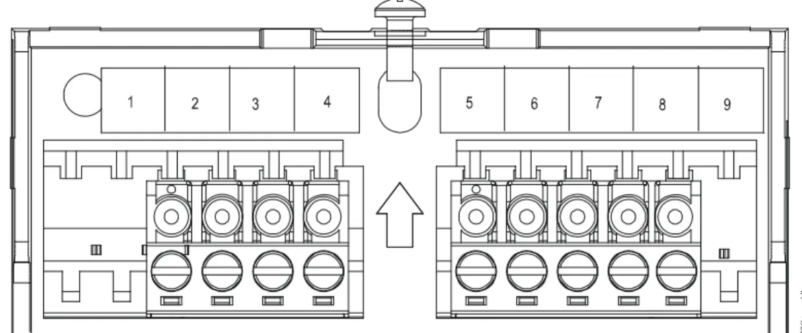
Figure 3: Terminal Block Location and Wiring
FI G :t e rm _b lk
Table 1: Terminal Block Wiring Terminal Signal Designation
1 Temperature Sensor and Manual Override
2 Temperature Sensor Common
3 Setpoint Common and LED Common
4 Setpoint
5 24 VAC (+15 VDC – VMA Only1)
6 Common (for Power, RH Output, Zone Bus, or Manual Override)
7 Zone Bus
8 LED and Manual Override
1. The +15 VDC power supply is used only when an HE-6800 Series Humidity Transmitter is connected to a VMA Controller.
For all transmitter models, the factory default
LED mode is LED Mode:ON. The DIP switch positions enable/disable the functions listed in Table 3
Risk of Property Damage.
Do not use switch settings other than those shown in Figure 4. Using other switch settings may cause incorrect controller operation or damage to the element, controller, [and/or] controlled equipment.
Risque de dégâts matériels.
Ne pas utiliser un paramétrage des commutateurs différent de celui-ci illustré à la Figure 4. L'utilisation d'autres paramètres de commutateurs risque de provoquer un fonctionnement incorrect du contrôleur ou d'endommager l'élément, le contrôleur [et/ou] l'équipement contrôlé.
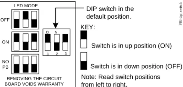
Figure 4: Controller Configuration DIP Switch Positions
DIP switch in the default position. KEY:
Switch is in up position (ON)
Switch is in down position (OFF) Note: Read switch positions from left to right.
LED MODE OFF ON NO PB N O 1 2 3
REMOVING THE CIRCUIT BOARD VOIDS WARRANTY
FIG :di p_ sw it c h
Table 2: Controller Compatibility with LED Mode and PB Types of HE-6800 LED Mode (Figure 4) Features Enabled on HE-6800
Features Recognized by Controller AHU UNT1100 VAV1xx or
UNT1xx
VMA12 Series1
VMA14 Series1
All Models LED Off2 Sensor and Manual Override
No Yes Yes Yes Yes
LED On Sensor, Manual Override, and LED No No No Yes Yes No PB Room Sensor Only
Yes Yes Yes Yes Yes
1. For these controllers, the LED appears brighter when pressing the manual override PB. 2. Holding the manual override PB for more than 2 seconds may affect the sensor reading.
Table 3: LED Mode and Functions
LED Mode Functions Switch Positions Enabled Disabled
OFF Sensor, PB LED Switch positions are down, up, and down. The LED remains off at all times.
ON LED, Sensor,
PB
--- Switch positions are factory set up, down, and up. The controller determines the LED mode.
The HE-6800 also features a power supply selection DIP switch. If you are using the transmitter where supply voltage is 24 VAC or higher, set this switch to ON.
Temperature Setpoint
Adjust the setpoint using the setpoint adjustment dial. Rotate clockwise to raise the temperature; rotate counterclockwise to lower the temperature.
Troubleshooting
HE-6800 Series Humidity Transmitters are recommended for use only with Johnson Controls digital controllers. If the HE-6800 is not functioning properly, use the following procedure to identify the problem and determine a solution:
1. Check that the HE-6800 is mounted in a location indicative of the space temperature (for example, away from drafts or sunlight).
2. Verify that the wiring is correct.
3. Check all supply voltage connections. See Figure 1, Figure 2, or Figure 3, if necessary. 4. Check the settings:
• Verify that any scaling modifications, setpoint adjustments, and overrides have been saved and downloaded to the controller.
• Check the override status (Temporary
Occupancy mode vs. Unoccupied mode) at the controller.
• Check the setpoint settings. 5. Confirm DIP switch positions if:
• the LED remains on or is dim
• the room sensor reading is outside of the normal range for the space being sensed Note: Make sure the DIP switch setting is correct for the controller used with the HE-6800.
6. Replace the HE-6800 if the troubleshooting suggestions fail to remedy the problem.
Accessories
Contact the nearest Johnson Controls representative to order any of the parts listed in Table 4.
Note: Review the technical specifications of the accessories prior to their use in an application.
Repair Information
Do not field repair the HE-6800 Series Humidity Transmitters. As with any electrical device, keep the air vents clean and free from dust or obstruction. If an HE-6800 Series Humidity Transmitter fails to operate within its specifications, replace the unit. For a replacement transmitter, contact the nearest Johnson Controls representative.
Figure 5: Humidity Output and Power Supply DIP Switch Positions
DIP switch in the default position.
KEY:
Switch is in up position (ON) Switch is in down position (OFF)
N O 1 2 F IG :pw r_ bs t_d s Switch 2
OFF = Low supply voltage operation ON = High supply voltage operation Switch 1
OFF = 0–10 VDC output, corresponding to 0–100%RH ON = 0–5 VDC output, corresponding to 0–100%RH
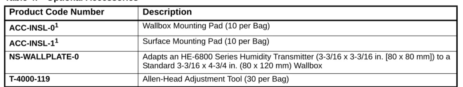
Table 4: Optional Accessories
Product Code Number Description
ACC-INSL-01 Wallbox Mounting Pad (10 per Bag) ACC-INSL-11 Surface Mounting Pad (10 per Bag)
NS-WALLPLATE-0 Adapts an HE-6800 Series Humidity Transmitter (3-3/16 x 3-3/16 in. [80 x 80 mm]) to a Standard 3-3/16 x 4-3/4 in. (80 x 120 mm) Wallbox
T-4000-119 Allen-Head Adjustment Tool (30 per Bag)
1. These foam pads help prevent drafts from entering the unit through the wall, and make installation easier when mounting on an uneven surface.
Technical Specifications
HE-6800 Series Humidity Transmitters with Temperature Sensor (Part 1 of 2)
Power Requirements 4.5 to 7.5 mA at 14 to 30 VDC and 5K ohm Load, or 18 to 25 mA at 20 to 30 VAC and 5K ohm Load
Terminations 9-Position Screw Clamp Terminal Block
Wire Size 16 to 24 AWG (1.3 to 0.6 mm Diameter); 18 AWG (1.0 mm Diameter) Recommended
Temperature Measurement Range 32 to 131°F (0 to 55°C)
Humidity Measurement Range Full Range 0 to 100% RH Calibrated Range 10 to 90% RH Temperature Sensor Nickel (HE-68Nx Models)
Sensor Type 1,000 ohm Thin Film Nickel
Coefficient Approximately 3 ohm per F° (5.4 ohm per C°)
Reference Resistance 1,000 ohm at 70°F (0°C) Accuracy ±0.34F° at 70°F (±0.18C° at 21°C) Platinum (HE-68Px Models)
Sensor Type 1,000 ohm Thin Film Platinum
Coefficient Approximately 2 ohm per F° (3.9 ohm per C°)
Reference Resistance 1,000 ohm at 32°F (0°C) Accuracy ±0.35F° at 70°F (±0.19C° at 21°C) Nonlinear NTC, Thermistor, Type II (HE-686x Models)
Sensor Type 10,000 ohm NTC Thermistor
Coefficient Nonlinear NTC, Johnson Controls Type II
Reference Resistance
10,000 ohm at 77°F (25°C)
Accuracy ±0.9F° (±0.5C°) at 32 to 158°F (0 to 70°C)
Humidity Sensor Type Capacitive Polymer Sensor
Humidity Element Accuracy
HE-68x2 Models ±2% RH for 20 to 80% RH at 50 to 95°F (10 to 35°C);
±4% RH for 10 to 20% RH and 80 to 90% RH at 50 to 95°F (10 to 35°C)
HE-68x3 Models ±3% RH for 20 to 80% RH at 77°F (25°C);
±6% RH for 10 to 20% RH and 80 to 90% at 77°F (25°C)
Setpoint Range Warmer/Cooler
Temperature Sensor Time Constant 10 Minutes at 10 ft per Minute
Manual Override Integral Momentary Pushbutton (DIP Switch Selectable)
LED GreenLED Indicates Three Modes of Operation (VMA12 and VMA14 Series
Controllers Only)
Ambient Operating Conditions 32 to 131°F (0 to 55°C), 10 to 95% RH Noncondensing; 86°F (30°C) Maximum Dew Point
Ambient Storage Conditions -40 to 140°F (-40 to 60°C), 5 to 95% RH Noncondensing; 86°F (30°C) Maximum Dew Point
Materials White Thermoplastic Protection: IP30 (EN 60529)
Dimensions (H x W x D)
HE-68xx-0 Models 3-3/16 x 3-3/16 x 1-5/16 in. (80 x 80 x 32 mm)
Compliance United States UL Listed, File E107041,
CCN PAZX, Under UL 916, Energy Management Equipment
Canada UL Listed, File E107041,
CCN PAZX7, Under CAN/CSA C22.2 No. 205, Signal Equipment
Europe CE Mark – Johnson Controls, Inc., declares that this product is in compliance with the essential requirements and other relevant provisions of the
EMC Directive, WEEE Directive, and RoHS Directive.
Australia and New Zealand
RCM, Australia/NZ Emissions Compliant
The performance specifications are nominal and conform to acceptable industry standards. For application at conditions beyond these specifications, consult the local Johnson Controls office. Johnson Controls, Inc. shall not be liable for damage resulting from misapplication or misuse of its products.
European Single Point of Contact: NA/SA Single Point of Contact: APAC Single Point of Contact:
JOHNSON CONTROLS WESTENDHOF 3 45143 ESSEN GERMANY JOHNSON CONTROLS 507 E MICHIGAN ST MILWAUKEE WI 53202 USA JOHNSON CONTROLS C/O CONTROLS PRODUCT MANAGEMENT
NO. 22 BLOCK D NEW DISTRICT WUXI JIANGSU PROVINCE 214142 CHINA