properties of Extension of
Steel Wire Ropes
Any assembly of steel wires spun into a helical formation, either as a strand or wire rope, when subjected to a tensile load, can extend in three separate phases, depending on the magnitude of the applied load.
There are also other factors that produce rope extension that are very small and can normally be ignored.
phase 1 — Initial or permanent
Constructional Extension
At the commencement of loading a new rope, extension is created by the bedding down of the assembled wires with a corresponding reduction in overall diameter. This reduction in diameter is accommodated by a lengthening of the helical lay. When sufficiently large bearing areas have been generated on adjacent wires to withstand the circumferential compressive loads, this mechanically created extension ceases and the extension in Phase 2 commences. The initial extension of any rope cannot be accurately determined by calculation and has no elastic properties.
The practical value of this characteristic depends upon many factors, the most important being the type and construction of rope, the range of loads and the number and frequency of the cycles of operation. It is not possible to quote exact values for the various constructions of rope in use, but the following approximate values may be employed to give reasonably accurate results.
The above figures are for guidance purposes. More precise figures are available upon request.
phase 2 — Elastic Extension
Following Phase 1, the rope extends in a manner which complies approximately with Hookes Law (stress is proportional to strain) until the limit of proportionality or elastic limit is reached.
It is important to note that wire ropes do not possess a Young’s Modulus of Elasticity, but an "apparent" Modulus of Elasticity can be determined between two fixed loads.
The Modulus of Elasticity also varies with different rope
constructions, but generally increases as the cross-sectional area of steel increases. By using the values given, it is possible to make a reasonable estimate of elastic extension, but if greater accuracy is required, it is advisable to carry out a modulus test on an actual sample of the rope. As rope users will find it difficult to calculate the actual metallic steel area, the values can be found in the Wire Rope Users Manual or obtained from Bridon Engineering.
Elastic Extension = (inches)
W = load applied (pounds)
L = rope length (inches)
E = elastic modulus (pounds/in2)
A = rope area (in2)
phase 3 — permanent Extension
The permanent, non-elastic extension of the steel is caused by tensile loads exceeding the yield point of the material.
If the load exceeds the limit of proportionality, the rate of extension will accelerate as the load is increased, until a loading is reached at which continuous extension will commence, causing the wire rope to fracture without any further increase of load.
Thermal Expansion and Contraction
The coefficient of linear expansion (∝) of steel wire rope is (6.94 x10⁻⁶ per °F) and therefore the change in length of 1 foot of rope
produced by a temperature change of t (°F) would be: Change in length ∆L = ∝L. t where
∝ = coefficient of linear expansion L = original length of rope (in) t = temperature change (°F)
The change will be an increase in length if the temperature rises and a decrease in length if the temperature falls.
Extension due to rotation
The elongation caused by a free rope end being allowed to rotate. Extension due to wear
The elongation due to inter-wire wear, which reduces the cross-sectional area of steel and produces extra constructional extension. Example: What will be the total elongation of a 200' length of 11⁄8" diameter Blue Strand 6x41 IWRC wire rope at a tension of
20,000 Ib and with an increase in temperature of 20°F.
Permanent Constructional Extension = 0.25% of rope length = .5 = 6" Elastic Extension = = = 5.73"
Thermal Expansion = ∆L = ∝Lo t =6.94 x 106 x 200 x 20 = .33" Therefore total extension = 6" + 5.73" + .33" = 12.06"
% of Rope Length Fiber Core SteelCore
Lightly loaded Factor of Safety about 8:1 0.25 0.125 Normally loaded Factor of Safety
about 5:1 0.50 0.25 Heavily loaded Factor of Safety about 3:1 0.75 0.50
Heavily loaded with many bends
and/or deflections Up to 2.00 Up to 1.00
Technical Information
WL EA 20,000 x 200 x 1213,500,000 x .62 WL EApressures Between Ropes
and Sheaves or Drums
In addition to bending stresses experienced by wire ropes operating over sheaves or pulleys, ropes are also subjected to radial pressure as they make contact with the sheave. This pressure sets up shearing stresses in the wires, distorts the rope’s structure, and affects the rate of wear of the sheave grooves. When a rope passes over a sheave, the load on the sheave bearing results from the tension in the rope and the angle of rope contact. It is independent of the diameter of the sheave.
Load on bearing =
T = rope tension (pounds) θ = angle of rope contact
Assuming that the rope is supported in a well-fitting groove, then the pressure between the rope and the groove is dependent upon the rope tension and diameter but is independent of the arc of contact.
Pressure, P =
P = pressure (psi) T = rope tension (pounds) D = diameter of sheave or drum (in) d = diameter of rope (in)
It must be realized that this method of estimation of pressure assumes that the area of contact of the rope in the groove is on the full rope diameter, whereas in fact only the crowns of the outer wires are actually in contact with the groove. It is estimated that the local pressures at these contact points may be as high as five times those calculated.
If the pressure is high, the compressive strength of the material in the groove may be insufficient to prevent excessive wear and indentation and this in turn will damage the outer wires of the rope and affect its working life. As with bending stresses, stresses due to radial pressure increase as the diameter of the sheave decreases. Although high bending stresses generally call for the use of flexible rope constructions having relatively small-diameter outer wires, these have less ability to withstand heavy pressures than do the larger wires in the less flexible constructions. If the calculated pressures are too high for the particular material chosen for the sheaves or drums or indentations are being experienced, consideration should be given to an increase in sheave or drum diameter. Such a modification would not only reduce the groove pressure, but would also improve the fatigue life of the rope.
The pressure of the rope against the sheave also causes distortion and flattening of the rope structure. This can be controlled by using sheaves with the correct groove profile which, for general purposes, suggests a recommended groove diameter of nominal rope diameter +6%. The profile at the bottom of the groove should be circular over an angle of approximately 120°, and the angle of flare between the sides of the sheave should be approximately 52°.
Hardness of Rope Wire
Recommended pulley hardness: 250-300 Brinell for Mn steel or equivalent alloy steel.
Design Factor
(Minimum Rope Breaking Strength /
Maximum Load on Rope)
Industry standards provide minimum design factors allowed for certain rope applications. Some typical minimum design factors follow:
Mobile crane Hoist rope 3.5
Hoist rope (rotation resistant) 5
Boom hoist rope 3.5
Wire rope slings 5
Tower cranes 5
Offshore pedestal cranes 5
Drill lines 3 Overhead cranes 5 2T sin θ 2 2T Dd
Rope grade Approximate Hardness Minimum Tensile Strength Brinel Rockwell 'C'
EEIP 444/486 46-50 EIP 415/461 44-48 IPS 388/444 42-46
Technical Information
Effects of D:d Ratio and loading on fatigue life
Typical example Dyform 6
Number of bends to rope failure
Sheave D:d ratio 30 29 28 27 26 5% MBL 10% MBL 20% MBL 25 24 23 22 21 20 19 18 17 16
Service life curve for various D:d ratios
D:d ratio 0 100 80 60 40 20 0 5 10 15 20 25 30 35 40 45 50 55 60 65
Relative Rope Service Life
Oversize Tolerance
Wire ropes are manufactured slightly larger than the nominal diameter. The maximum allowable oversize tolerances provided by industry standards are shown in the following table:
Bending Ratios D:d
Typical minimum bending ratios (sheave or drum dia : rope dia) provided by some industry standards are as follows:
Drum Sheave
Mobile crane Load hoist 18 18
Boom hoist 15 15 Load block 16
Tower crane Hoist 18 18
Load block 16
Rotary drilling Drill Line 20 20
Offshore pedestal crane Hoist 18 18
Surface mining Hoist 24 24
Drag 22 22
Nominal Rope Diameter Tolerance Under Over Up to 1/8" -0 +8% Over 1/8” to 3/16" -0 +7% Over 3/16” to 5/16" -0 +6% Over 5/16" -0 +5%
Bend Fatigue
Bend fatigue testing of ropes usually consists of cycling a length of rope over a sheave while the rope is under a constant tension. As part of its ongoing development program, Bridon has tested literally thousands of ropes in this manner over the years on its own in-house design bend testing equipment.
Through this work, Bridon has been able to compare the effects of rope construction, tensile strength, lay direction, sheave size, groove profile and tensile loading on bend fatigue performance under ideal operating conditions. At the same time it has been possible to compare rope life to discard criteria (e.g., as laid down in ISO 4309) with that to complete failure of the rope, i.e., to the point where the rope has been unable to sustain the load any longer. As part of the exercise, it has also been possible to establish the residual breaking strength of the rope at discard level of deterioration.
What needs to be recognized, however, is that very few ropes operate under these controlled operating conditions, making it very difficult to use this base information when attempting to predict rope life under other conditions. Other influencing factors, such as dynamic loading, differential loads in the cycle, fleet angle, reeving arrangement, type of spooling on the drum, change in rope direction, sheave alignment, sheave size and groove profile, can have an equally dramatic effect on rope performance.
However, the benefit of such testing can be particularly helpful to the rope manufacturer when developing new or improving existing products.
If designers or operators of equipment are seeking optimum rope performance or regard bending fatigue life as a key factor in the operation of equipment, such information can be provided by Bridon for guidance purposes.
The Use of Swivels with Wire Rope
Under certain circumstances it may be necessary to use a swivel in a lifting system to prevent rotation of the load. This is typically done for employee safety considerations. It is possible however, that the use of a swivel will have an adverse affect on rope performance and may in some cases damage the wire rope.There are many types of accessories available that incorporate different types and degrees of rotation preventing swivels. The swivel may be either an independent accessory or an integral part of a lifting device such as a crane block with a swivel hook. A typical independent accessory is a ball bearing anti-friction swivel. There are also headache balls with swivel hooks.
The type of swivel that causes the most concern from the standpoint of the wire rope is the independent anti-friction swivel that attaches directly to the rope. The purpose of using a swivel in a lifting system is to prevent rotation of the load. This then allows the wire rope to rotate. Excessive rope rotation can damage a wire rope.
To assist in determining whether or not a swivel should be used in the lifting system, the following recommendations should be considered. It must also be recognized that the rotation characteristics of different types and constructions of wire rope vary considerably. The following types and constructions of wire rope are grouped according to their rotation characteristics.
group 1
Wire rope constructions having very high rotation characteristics should not be used with a swivel under any circumstances. These rope constructions will rotate excessively with one end free to rotate and the rope will unlay and distort and be easily damaged with a loss of rope breaking force.
• Blue Strand 6x19 and 6x36 Class Lang Lay
• All constructions of Triangular (flattened) Strand Lang Lay • Endurance Dyform 8 Lang Lay
• Constructex
group 2
Wire rope constructions having high rotation characteristics when used in single part reeving may require a swivel in the system to prevent rotation in certain operating conditions. However, this should be done only when employee safety is the issue. These rope constructions when used in a reeving system with one end free to rotate will have a high level of rotation. This will cause the rope to unlay to some degree and distortion of the rope will occur.
• Blue Strand 6x19 and 6x36 Class Regular Lay • Endurance Dyform 6 and 8 Regular Lay
group 3a and 3b
The ropes in this Group are designed with an inner rope that is laid in the opposite direction to the outer strands to provide a medium resistance to rotation. Ropes with medium rotation characteristics are used with a swivel in single part reeving applications. However, a swivel is not recommended for multiple-part hoisting applications or in any application where the swivel is not necessary for safety reasons. If it is necessary to use a swivel the rope must be operating within the design factor of 5, must not be shock loaded and must be inspected daily by a qualified person for distortion. It should be noted that if a swivel is used in conjunction with Group 3a ropes, rope service life might be reduced due to increased internal wear between the outer strands and the inner rope. group 3a - Endurance 8RR Rotation Resistant
- Endurance 19 Rotation Resistant group 3b - Endurance Dyform 18 Rotation Resistant
group 4
Wire ropes having low rotation characteristics used in either single or multiple part reeving may be used with a swivel. The reason for this is that the ropes will exhibit very little, if any, rotation when used at the proper design factor. Application parameters such as a fleet angle may induce turn into a wire rope that can be relieved by the use of a swivel. However, if the application does not induce any turn into the rope or if a swivel is not beneficial to the performance of the rope the swivel may not be necessary.
• Endurance 35 LS
• Endurance Dyform34LR /PI/MAX
NOTE: When using a swivel with any wire rope, frequent inspection of the rope is necessary. The rope should not be shock loaded or overloaded.
Technical Information
Fleet Angle
Of all the factors that have some influence on the winding of a rope on a smooth drum, the fleet angle, arguably, has the greatest effect.
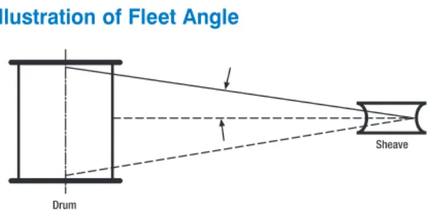
Fleet angle is usually defined as the included angle between two lines, one that extends from a fixed sheave to the flange of a drum and the other that extends from the same fixed sheave to the drum in a line perpendicular to the axis of the drum. (See illustration.)
Illustration of Fleet Angle
If the drum incorporates helical grooving, the helix angle of the groove needs to be added or subtracted from the fleet angle as described above to determine the actual fleet angle experienced by the rope.
At the drum
When spooling rope onto a drum, it is generally recommended that the fleet angle is limited to between 0.5° and 2.5°. If the fleet angle is too small, i.e., less than 0.5°, the rope will tend to pile up at the drum flange and fail to return across the drum. In this situation, the problem may be alleviated by introducing a kicker device or by increasing the fleet angle through the introduction of a sheave or spooling mechanism.
If the rope is allowed to pile up, it will eventually roll away from the flange, creating a shock load in both the rope and the structure of the mechanism; an undesirable and unsafe operating condition.
Excessively high fleet angles will return the rope across the drum prematurely, creating gaps between wraps of rope close to the flanges as well as increasing the pressure on the rope at the crossover positions.
Even where helical grooving is provided, large fleet angles will inevitably result in localized areas of mechanical damage as the wires "pluck" against each other. This is often referred to as "interference," but the amount can be reduced by selecting a Langs lay rope if the reeving allows. The interference effect can also be reduced by employing a Dyform rope, which offers a much smoother exterior surface than conventional
rope constructions.
Floating sheaves or specially designed fleet angle
compensating devices may also be employed to reduce the fleet angle effect.
At the sheave
Where a fleet angle exists as the rope enters a sheave, it initially makes contact with the sheave flange. As the rope continues to pass through the sheave, it moves down the flange until it sits in the bottom of the groove. In doing so, even when under tension, the rope will actually roll as well as slide. As a result of the rolling action, the rope is twisted, i.e., turn is induced into or out of the rope, either shortening or lengthening the lay length of the outer layer of strands. As the fleet angle increases so does the amount of twist.
To reduce the amount of twist to an acceptable level, the fleet angle should be limited to 2.5° for grooved drums and 1.5° for plain drums, and when using rotation-resistant ropes, the fleet angle should be limited to 1.5°.
However, for some crane and hoist applications it is recognized that for practical reasons it is not always possible to comply with these general recommendations, in which case the rope life could be affected.
Rope Torque
The problem of torsional instability in crane hoist ropes would not exist if the ropes could be perfectly torque balanced under load. The torque generated in a wire rope under load is usually directly related to the applied load by a constant torque factor. For a given rope construction, the torque factor can be expressed as a proportion of the rope diameter and this has been done below.
Variation with rope construction is relatively small, and hence the scope for dramatically changing the stability of a hoisting system is limited. Nevertheless the choice of the correct rope can have a deciding influence, especially in systems that are operating close to the critical limit. It should be noted that the rope torque referred to here is purely that due to tensile loading. No account is taken of the possible residual torque due, for example, to rope manufacture or installation procedures.
Torsional Stability
Torsional stability and the cabling graph (see page 46) are two methods that can be used to determine torsional stability or the tendency of the rope to cable. The torque factors quoted on page 47 are approximate maximum values for the particular constructions. To calculate the torque value for a particular rope size multiply by the nominal rope diameter. Example: for 20 mm dia. Dyform 34LR at 20% of minimum breaking force
Torque value = torque factor x rope dia. = 0.76% x 20 mm = 0.152 mm
To calculate the torque generated in a particular rope when subjected to a tensile load, multiply the load by the torque value and combine the units.
Example: for 20 mm dia. Dyform 34LR at 6000 kgf load Torque generated = torque value x load
= 0.152 . 6000 = 912 kgf.mm
Fleet angle
Drum
The torsional characteristics of wire rope will have the effect of causing angular displacement of a sheave block when used in multi-fall reeving arrangements. The formula below gives a good approximation under such arrangements.
S2 = 4000L. Tv
sin θ
Where S is the rope spacing in mm
L is the length of each part in the reeving Tv is the torque value of the rope
θ is the angular displacement of the sheave block When the angular displacement of the sheave block exceeds 90° (sin θ = 1) torsional instability results and cabling of the reeving will occur. Therefore the test for stability of any particular reeving can be expressed as:
S > 4 000 L. Tv
Where S is the rope spacing in mm L is length of each part in meters Tv is torque value in mm
The preceding equations are all relative to a simple two part reeving. For more complex systems a similar approach may be used if account is taken of the different spacings of the ropes.
Even Number of Falls
Note: For hoisting arrangements in which the rope falls are not parallel an average rope spacing should be used.
Uneven Number of Falls
(Rope termination at bottom block) Rope Plan
Effective Rope Spacing and modified formula for stable condition
Effective Rope Spacing S
Stable condition if S > 4 000 . L. Tv
Angular displacement of block
To predict the amount of angular displacement by which a sheave block may turn under the influence of rope torque:
sin θ = (4 000 L. Tv)
S2
(for even number of falls)
The equations assume that rope is torque-free in the no-load condition, therefore, induced torque during or immediately after installation will adversely influence the calculated effect. The above data assumes a constant torque value which is a valid assumption for a new rope. Wear and usage can have a significant effect on the torque value but practical work shows that under such circumstances the torque value will diminish, thus improving the stability of the arrangement. Some arrangements may be of such complexity that the evaluation demands a computer study.
Examples:
Assuming a pedestal crane working on two falls is roped with 20 mm diameter Dyform 34LR and the bottom block carries a sheave of 360 mm diameter with the falls parallel:
Torque value = 0.76% x 20 = 0.152 mm
If the rope is new (worst condition) and no account is taken of block weight and friction, then angular displacement for a height of lift of 30 meters is given by
sin θ = (4 000 . 30 . 0.152) 3602
= 0.141 i.e. 8° 10'
The reeving would be expected to cable at a height of lift calculated as: L = S2 4 000 . Tv = 3602 4 000 . 0.152 = 213 metres
From the crane designer’s viewpoint a safety factor against cabling should be recognized (angular displacement limited at 30°) hence the practical height of lift is approximately 106.5 meters.
Effective Rope Spacing Rope Plan
Technical Information
Cabling graph
Field research jointly conducted by the Wire Rope Technical Board and the Power Crane and Shovel Association has shown that cabling of the rope parts in a multiple-part reeved hoisting arrangement is controlled by several factors. The following calculations and graphs can be used to determine when and if cabling will occur on multiple-part reeved hoisting arrangements.
The graph illustrates two-dimensional ratios. They are: 1. L/s = Length of fall per unit rope spacing
2. D/d = Average pitch diameter of traveling and crown block sheave per unit rope diameter
Various constructions of rope shown on the graph indicate the limited conditions for torsional stability with the angular displacement of the hoist block to a maximum of 90°. When the operating conditions for a particular installation give a resultant above the appropriate band, then cabling of the falls will most likely occur. If the operating conditions give a resultant below any particular band, the cabling of the falls will most likely not occur. If the operating conditions for any particular installation fall within the band, cabling is unpredictable.
3
2
1
4
Band 1 6x19 and 6x36 Class ropes, Endurance Dyform 6 and 8 Band 2 Endurance 8RR
Band 3 Endurance Dyform 18, Endurance 19 Band 4 Endurance Dyform 34LR, Endurance 35LS L = length of fall (ft)
s = average rope spacing (ft)
D = average pitch diameter of point and block sheaves (in) d = nominal rope diameter (in)
300 250 200 150 100 50 D/d L/s 5 10 15 20 25 30
Stable if below band Unstable if above band Uncertain if in band
S
2/
3of 2 part
2 part
3 part
4/
5of 4 part
4 part
5 part
S
6/
7of 6 part
6 part
7 part
S
S is determined as follows S = Spacing (Ft)Summary Technical Information and Conversion Factors
(For guidance purposes only)
Bridon supplies a range of Endurance high performance steel wire ropes specifically designed and manufactured to meet the needs of today’s cranes and the demanding applications to which they are exposed. High performance ropes are normally selected by customers when they require the specific characteristics of improved performance, high strength, low extension, or low rotation.
Rope Construction FactorFill %
Extension characteristics Rotational characteristics Rope modulus at 20% of breaking force psi Initial permanent extension % Torque factor at 20% of breaking force % Turn value at 20% of breaking force degrees/rope lay
6 & 8 Strand High performance
Endurance Dyform 6 69.0 13,500,000 0.10 7.50 58 Endurance Dyform 8 66.2 12,600,000 0.15 8.74 91 Endurance Dyform 8PI 66.8 12,600,000 0.16 9.55 94
Rotation-Resistant
Endurance 19 61.3 10,000,000 0.24 6.60 5
Endurance Dyform 18 72.8 14,000,000 0.09 4.50 4 Endurance Dyform 18PI 71.1 14,000,000 0.11 3.80 2.6
Endurance 35ls 63.8 14,000,000 0.10 0.76 0.2 Endurance Dyform 34lr/34LRPI 77.3 14,500,000 0.05 0.76 0.2
Conventional Constructions
Blue Strand 6x36 61.7 12,600,000 0.17 7.75 56 Blue Strand 6x19 62.4 13,500,000 0.15 7.10 42
Force Mass
1 kN = 0.101 972 Mp 1 UK tonf = 9.964.02 N 1 kg = 2.204 62 lb 1 lb = 0.453 592 kg 1 N = 0.101 972 kgf 1 lbf = 4.448 22 N 1 tonne (t) = 0.984 207 UK ton 1 UK ton = 1.01605 tonnes (t) 1 kgf = 9.806 65 N 1 lbf = 0.453 592 kgf 1 kg/m = 0.671 970 lb/ft 1 lb/ft = 1.488 kg/m 1 kgf = 1 kp 1 UK tonf = 1.01605 tonne 1 kg = 1000 g 1 kip (USA) = 1000 lb
1 N = 1.003 61 x 104 UK tonf 1 UK tonf = 9.964 02 kN 1 Mp = 1 x 10⁶ g
1 N = 0.2244 809 lbf 1 UK tonf = 2240 lbf
1 kgf = 2.204 62 lbf 1 short tonf Length
1 t = 0.984 207 UK tonf (USA) = 2000 lbf 1 m = 3.280 84 ft 1 ft = 0.304 8 m 1 kN = 0.100 361 UK tonf 1 kip (USA) = 1000 lbf 1 km = 0.621 371 miles 1 mile = 1.609 344 km
1 kip = 453.592 37 kgf
pressure/Stress Area
1 N/mm2 = 0.101972 kgf/mm2 1 mm2 = 0.001 55 in2 1 in2 = 645.16 mm2
1 kgf/mm2 = 9.806 65 N/mm2 1 m2 = 10.763 9 ft2 1 ft2 = 0.092 903 0 m2
1 N/mm2 = 1 MPa
1 kgf/mm2 = 1 422.33 lbf/in2 1 lbf/in2 = 7.030 x 10⁻⁴ kgf/mm2 Volume
1 kgf/mm2 = 0.634 969 tonf/in2 1 tonf/in2 = 1.574.88 kgf/mm2 1 cm3 = 0.061 023 7 in3 1 in3 =16.387 1 cm3
1 N/m2 = 1.450 38 x 10-4lbf/in2 1 lbf/in2 = 6.894.76 N/m2 1 litre (1) = 61.025 5 in3 1 in3 = 16.386 6 ml
1 N/m2 = 1 x 10⁻⁶N/mm2 1 tonf/in2 = 1.544 43 x 108 dyn/cm2 1 m3 = 6.102 37 x 104 in3 1 yd3 = 0.764 555 m3
1 bar = 14.503 8 lbf/in2
1 hectobar = 10 N/mm2
1 hectobar = 107 N/m2
Guide to Examination
guide to Examination
The continued safe operation of lifting equipment, lifting accessories (e.g., slings) and other systems employing wire rope depends to a large extent on the operation of well-programmed periodic rope examinations and the assessment by the competent person of the fitness of the rope for further service.
Examination and discard of ropes by the competent person should be in accordance with the instructions given in the original equipment manufacturer’s handbook. In addition, account should be taken of any local or application specific regulations.
The competent person should also be familiar, as appropriate, with the latest versions of related ASME B30, International, European, or National standards.
particular attention must be paid to those sections of rope which experience has shown to be liable to deterioration. Excessive wear, broken wires, distortions and corrosion are the more common visible signs of deterioration (see below). Note: This publication has been prepared as an aid for rope examination and should not be regarded as a substitute for the competent person. Wear is a normal feature of rope service and the use of the correct rope construction ensures that it remains a secondary aspect of deterioration. Lubrication may help to reduce wear. Broken wires are a normal feature of rope service towards the end of the rope’s life, resulting from bending fatigue and wear. The local breakup of wires may indicate some mechanical fault in the equipment. Correct lubrication in service will increase fatigue performance.
Distortions are usually a result of mechanical damage, and if severe, can considerably affect rope strength.
Visible rusting indicates a lack of suitable lubrication, resulting in corrosion. Pitting of external wire surfaces becomes evident in some circumstances. Broken wires ultimately result.
Internal corrosion occurs in some environments when lubrication is inadequate or of an unsuitable type. Reduction in rope diameter will frequently guide the observer to this condition. Confirmation can only be made by opening the rope with clamps or the correct use of spike and needle to facilitate internal inspection.
Note: Non-destructive testing (NDT) using electromagnetic means may also be used to detect broken wires and/or loss in metallic area. This method complements the visual examination but does not replace it. pictures courtesy of S.M.R.E. Crown Copyright 1966
Factors Affecting Rope performance
Multi-layers of the rope on the drum can result in severe distortion in the underlying layers.Bad spooling (due to excessive fleet angles or slack winding) can result in mechanical damage, shown as severe crushing, and may cause shock loading during operation. Small-diameter sheaves can result in permanent set of the rope, and will certainly lead to early wire breaks. Oversize grooves offer insufficient support to the rope leading to increased localized pressure, flattening of the rope and premature wire fractures. Grooves are deemed to be oversize when the groove diameter exceeds the nominal rope diameter by more than 15%.
Undersize grooves in sheaves will crush and deform the rope, often leading to two clear patterns of wear and associated wire breaks.
Excessive angle of fleet can result in severe wear of the rope due to scrubbing against adjacent laps on the drum. Rope deterioration at the termination may be exhibited in the form of broken wires. An excessive angle of fleet can also induce rotation causing torsional imbalance.
Some of the More Common Types of
Wire Fractures Can Include:
A
Severed bywear
B
TensionC
FatigueD
Corrosion fatigueTypical Examples of Wire Rope Deterioration
Mechanical damage due to rope movement over sharp edge projection while under load.
1
Typical wire fractures as a result of bend fatigue.9
Localized wear due to abrasion on supporting structure.
2
Wire fractures at the strand, or core interface, as distinct from "crown" fractures.10
Narrow path of wear resulting in fatigue fractures, caused by working in a grossly oversize groove, or over small support rollers.
3
Breakup of IWRC resulting from high stress application.11
Two parallel paths of broken wires indicative of bending through an undersize groove in the sheave.
4
Looped wires as a result of torsional imbalance and/or shock loading.12
Severe wear, associated with high tread pressure.5
Typical example of localized wear and deformation.13
Severe wear in Langs Lay, caused by abrasion.
6
Multi-strand rope "bird caged" due to torsional imbalance.14
Severe corrosion.
7
Protrusion of rope center resulting from buildup of turn.15
Internal corrosion while external surface shows little evidence of deterioration.
8
Substantial wear and severe internal corrosion.Troubleshooting Guide
The following is a simplified guide to common wire rope problems. In the event of no other standard being applicable, Bridon recommends that ropes are inspected/examined in accordance with ASME B30.5.
problem Cause/Action
Mechanical damage caused by the rope contacting the structure of the crane on which it is operating or an external structure — usually of a localized nature.
• Generally results from operational conditions.
• Check sheave guards and support/guide sheaves to ensure that the rope has not “jumped out” of the intended reeving system.
• Review operating conditions.
Opening of strands in rotation-resistant ropes — in extreme circumstances the rope may develop a “birdcage distortion” or protrusion of inner strands.
Note — rotation-resistant ropes are designed with a specific strand gap which
may be apparent on delivery in an off tension condition. These gaps will close under load and will have no effect on the operational performance of the rope.
• Check sheave and drum groove radii using sheave gauge to ensure that they are no smaller than nominal rope radius +2.5%. Bridon recommends that the sheave and drum groove radii are checked prior to any rope installation.
• Repair or replace drum/sheaves if necessary.
• Check fleet angles in the reeving system — a fleet angle in excess of 1.5 degrees may cause distortion (see page 56).
• Check installation method — turn induced during installation can cause excessive rope rotation resulting in distortion (see pages 55 to 58).
• Check if the rope has been cut on site prior to installation or cut to remove a damaged portion from the end of the rope. If so, was the correct cutting procedure used? Incorrect cutting of rotation-resistant, low-rotation and parallel closed ropes can cause distortion in operation (see page 56 to 57).
• Rope may have experienced a shock load.
Broken wires or crushed or flattened rope on lower layers at crossover points in multi-layer coiling situations.
Wire breaks usually resulting from crushing or abrasion.
• Check tension on underlying layers. Bridon recommends an installation tension of between 2% and 5% of the minimum breaking force of the wire rope. Care should be taken to ensure that tension is retained in service. Insufficient tension will result in these lower layers being more prone to crushing damage.
• Review wire rope construction. Dyform wire ropes are more resistant to crushing on underlying layers than conventional rope constructions.
• Do not use more rope than necessary.
• Check drum diameter. Insufficient bending ratio increases tread pressure.
Wires looping from strands.
• Insufficient service dressing. • Consider alternative rope construction.
• If wires are looping out of the rope underneath a crossover point, there may be insufficient tension on the lower wraps on the drum.
• Check for areas of rope crushing or distortion. • Possible fleet angle problems causing rope rotation.
“pigtail” or severe spiralling in rope.
• Check that the sheave and drum diameter is large enough. Bridon recommends a minimum ratio of the drum/sheave to nominal rope diameter of 18:1.
• Indicates that the rope has run over a small radius or sharp edge. • Check to see if the rope has “jumped off” a sheave and has run over a shaft.
problem Cause/Action
Two single axial lines of broken wires running along the length of the rope approximately 120 degrees apart indicating that the rope is being nipped in a tight sheave.
• Check sheave and drum groove radii using sheave gauge to ensure that they are no smaller than nominal rope radius + 2.5%. Bridon would recommend that the sheave/drum groove radii are checked prior to any rope installation. • Repair or replace drum/sheaves if necessary.
One line of broken wires running along the length of the rope indicating insufficient support for the rope, generally caused by oversize sheave or drum grooving.
• Check to see if the groove diameter is no greater than 15% greater than the nominal rope diameter.
• Repair or replace drum/sheaves if necessary. • Check for contact damage.
Short rope life resulting from evenly/randomly distributed bend fatigue wire breaks caused by bending through the reeving system.
Fatigue-induced wire breaks are characterized by flat ends on the broken wires.
• Bending fatigue is accelerated as the load increases and as the bending radius decreases (see page 42). Consider whether either factor can be improved. • Check wire rope construction. Dyform ropes are capable of doubling the bending
fatigue life of a conventional steel wire rope.
Short rope life resulting from localized bend fatigue wire breaks. Fatigue-induced wire breaks are characterized by flat ends on the broken wires.
• Bending fatigue is accelerated as the load increases and as the bending radius decreases (see page 42). Consider whether either factor can be improved. • Check wire rope construction. Dyform ropes are capable of doubling the bending
fatigue life of a conventional steel wire rope.
• Localized fatigue breaks indicate continuous repetitive bends over a short length. Consider whether it is economical to periodically shorten the rope in order to move the rope through the system and progressively expose fresh rope to the severe bending zone. In order to facilitate this procedure it may be necessary to begin operating with a slightly longer length of rope.
Broken rope — ropes are likely to break when subjected to substantial overload or misuse particularly when a rope has already been subjected to mechanical damage.
Corrosion of the rope both internally and/or externally can also result in a significant loss in metallic area. The rope strength is reduced to a level where it is unable to sustain the normal working load.
• Review operating conditions.
Wave or corkscrew deformations normally associated with rotation-resistant ropes.
• Check sheave and drum groove radii using sheave gauge to ensure that they are no smaller than nominal rope radius +2.5%. Bridon recommends that the sheave/drum groove radii are checked prior to any rope installation.
• Repair or replace drum/sheaves if necessary.
• Check fleet angles in the reeving system — a fleet angle in excess of 1.5 degrees may cause distortion (see page 44)
• Check that rope end has been secured in accordance with manufacturer's instructions (see page 56 and 57).
• Check operating conditions for induced turn.
Rotation of the load in a single fall system. • Review rope selection.
• Consider use of rotation-resistant rope.
Rotation of the load in a multi-fall system resulting in “cabling” of the rope falls. possibly due to induced turn during installation or operation.
• Review rope selection (see page 44 to 46 cabling calc.) • Consider use of rotation-resistant rope.
Troubleshooting Guide
problem Cause/Action
Core protrusion or broken core in single layer six– or eight-strand rope. • Caused by repetitive shock loading — review operating conditions.
Rope accumulating or “stacking” at drum flange due to insufficient
fleet angle. • Review drum design with original equipment manufacturer kicker, fleeting sheave, etc. — consider adding rope
Sunken wraps of rope on the drum normally associated with insufficient support from lower layers of rope or grooving.
• Check correct rope diameter. • If grooved drum check groove pitch.
• Check tension on underlying layers. Bridon recommends an installation tension of between 2% and 5% of the minimum breaking force of the wire rope. Care should be taken to ensure that tension is retained in service. Insufficient tension will result in these lower layers being more prone to crushing damage.
• Make sure that the correct rope length is being used. Too much rope (which may not be necessary) may aggravate the problem.
Short rope life induced by excessive wear and abrasion.
• Check fleet angle to drum.
• Check general alignment of sheaves in the reeving system. • Check that all sheaves are free to rotate.
• Review rope selection. The smooth surface of Dyform wire ropes gives better contact with drum and sheaves and offers improved resistance to interference betweeen adjacent laps of rope.
External corrosion. • Consider selection of galvanized rope.
• Review level and type of service dressing.
Internal corrosion.
• Consider selection of galvanized rope.
• Review frequency amount and type of service dressing. • Consider selection of plastic impregnated (PI) wire rope.
Product Safety:
Instructions and warnings on
the use of steel wire rope
The following instructions and warnings combine to provide guidance on product safety and are intended for use by those already having a working knowledge of wire ropes, as well as the new user. They should be read, followed and passed on to others.
Failure to read, understand and follow these instructions could result in harmful and damaging consequences.
1. Rope Selection Criteria
Ensure that the correct type of wire rope is selected for the equipment by referring to the OEM’s instruction manual or other relevant documents. If in doubt contact Bridon for guidance.
1.1 Rope strength
If necessary, refer to the appropriate regulations and/or application standards and calculate the maximum force to which the rope will be subjected.
The calculation may take into account the mass to be lifted or moved, any shock loading, effects of high speed, acceleration, any sudden starts or stops, frequency of operation and sheave bearing friction.
By applying the relevant design factor and, where applicable, the efficiency of the rope termination, the required minimum breaking load or force of the rope will be determined, the values of which are available from the relevant national or international standards or from specific product data literature. If in doubt ask for advice from Bridon.
1.2 Bending fatigue
The size and number of sheaves in the system will influence the performance of the rope.
Wire rope that bends around sheaves, rollers or drums will deteriorate through bending fatigue. Reverse bending and high speed will accelerate the process. Therefore, under such conditions select a rope with high bending fatigue resistance. Refer to product data information, and if in doubt ask for advice.
1.3 Abrasion
Wire rope that is subject to abrasion will become progressively weaker as a result of:
Externally — dragging it through overburden, sand or other abrasive materials and passing around a sheave, roller or drum.
Internally — being loaded or bent.
Abrasion weakens the rope by removing metal from both the inner and outer wires. Therefore, a rope with large outer wires should normally be selected.
1.4 Vibration
Vibration in wire rope will cause deterioration. This may become apparent in the form of wire fractures where the vibration is absorbed.
These fractures may be internal only and will not be visually identified. 1.5 Distortion
Wire rope can be distorted due to high pressure against a sheave, improperly sized grooves, or as a result of multi-layer spooling on a drum.
Rope with a steel core is more resistant to crushing and distortion.
1.6 Corrosion
Rope with a large number of small wires is more susceptible to corrosion than rope with a small number of large wires. Therefore, if corrosion is expected to have a significant effect on rope performance. The rope may have to be lubricated frequently in service or a galvanized rope may be selected.
1.7 Cabling
Cabling of rope reeving due to block rotation can occur if the rope is incorrectly selected. Applications involving high lifts are particularly vulnerable to this condition, therefore, ropes specifically designed to resist rotation need to be selected.
1.8 Fixing of rope ends
Ropes that have high rotation characteristics must not be selected unless both ends of the rope are fixed or the load is guided and unable to rotate.
1.9 Connecting ropes
In the event that it is necessary to connect one rope to another (in series) it is essential that they have the required strength, are of the same type and have the same lay direction (i.e., connect right lay to right lay). Failure to heed this warning could result in catastrophic failure particularly at a termination that is capable of being pulled apart (i.e., splice) due to unlaying.
1.10 Rope length
Rope length and/or difference in length between two or more ropes used in a set may be a critical factor and must be considered along with rope selection.
Wire rope will elongate under load. Other factors such as temperature, rope rotation and internal wear will also have an effect. These factors should also be considered during rope selection.
Product Safety:
Instructions and warnings on
the use of steel wire rope
1.11 preformed and non-preformed ropes
Single layer round-strand rope is normally supplied preformed. However, if a non-preformed rope is selected then personnel responsible for its installation and/or maintenance need to take particular care when handling such rope, especially when cutting. For the purposes of this instruction, rotation-resistant ropes should be regarded as non-preformed ropes.
1.12 Operating temperatures
Wire rope with a steel core should be selected if there is any evidence to suggest that a fiber core will not provide adequate support to the outer strands and/or if the temperature of the working environment may be expected to exceed 180˚F.
For operating temperatures above 200˚F de-rating of the minimum breaking force of the rope is necessary (e.g., between 200˚F and 400˚F reduce by 10%; between 200˚C and 300˚C reduce by 25%; between 600˚F and 800˚F reduce by 35%).
Do not use ropes with high carbon wires above 800˚F. Failure to observe this general guidance could result in failure of the ropes to support the load.
For temperatures over 800˚F, other materials such as stainless steel or other special alloys should be considered.
Rope lubricants and any synthetic filling and/or covering materials may become ineffective at certain low or high operating temperature levels.
Certain types of rope end terminations also have limiting operating temperatures and the manufacturer or Bridon should be consulted where there is any doubt. Ropes with aluminium ferrules must not be used at temperatures in excess of 300˚F.
2. Storage
2.1 Unwrap the rope and examine the rope immediately after delivery to check its identification and condition and verify that it is in accordance with the details on the certificates and/or other relevant documents.
Check the rope diameter and examine any rope terminations to ensure that they are compatible with the equipment or machinery to which they are to be fitted.
2.2 Select a clean, well-ventilated, dry, undercover location. Cover with waterproof material if the delivery site conditions preclude inside storage.
Rotate the reel periodically during long periods of storage, particularly in warm environments, to prevent migration of the lubricant from the rope.
Never store wire rope in areas subject to elevated temperatures as this may seriously affect its future performance. In extreme cases its original as-manufactured strength may be severely reduced rendering it unfit for safe use.
Ensure that the rope does not make any direct contact with the floor and that there is a flow of air under the reel. Failure to do so may result in the rope becoming contaminated with foreign matter and start the onset of corrosion before the rope is even put to work.
Support the reel on a simple A-frame or cradle, located on ground that is capable of supporting the total mass of rope and reel. Ensure that the rope is stored where it is not likely to be affected by chemical fumes, steam or other corrosive agents.
Failure to do so may seriously affect its condition rendering it unfit for safe use.
2.3 Examine ropes in storage periodically and, when necessary, apply a suitable dressing that is compatible with the manufacturing lubricant. Contact the rope supplier, Bridon or original equipment manufacturer’s (OEM) manual for guidance on types of dressings available, methods of application and equipment for the various types of ropes and applications.
Re-wrap the rope unless it is obvious that this will be detrimental to rope preservation.
Failure to apply the correct dressing may render the original manufacturing lubricant ineffective and rope performance may be significantly affected.
Ensure that the rope is stored and protected in such a manner that it will not be exposed to any accidental damage either during the storage period or when placing the rope in, or taking it out of storage.
Failure to carry out or pay attention to any of the above could result in a loss of strength and/or a reduction in performance. In extreme cases the rope may be unfit for safe use.
3. Certification and Marking
3.1 Make sure that the relevant certificate has been obtained before taking the rope into use for a lifting operation. Check to verify that the marking on the rope or its package matches the relevant certificate.
Note: The rating of a component part of a machine or lifting accessory is the responsibility of the designer of the machine or accessory. Any re-rating of a lifting accessory must be approved by a competent person.
3.2 Retain the certificate in a safe place for identification of the rope when carrying out subsequent periodic statutory examinations in service.
4. Handling and Installation
4.1 Handling and installation of the rope should be carried out in accordance with a detailed plan and should be supervised by a competent person.
Incorrectly supervised handling and installation procedures may result in serious injury to persons in the vicinity of the operation as well as those persons directly involved in the handling and installation. 4.2 Wear suitable protective clothing such as overalls,
industrial gloves, helmet, eye protectors, and safety footwear (and respirator, particularly where the emission of fumes due to heat is likely).
Failure to wear suitable protective clothing and equipment may result in skin problems from overexposure to certain types of rope lubricants and dressings; burns from sparks, rope ends, molten lubricants, and metals when cutting ropes or preparing sockets for reuse; respiratory or other internal problems from the inhalation of fumes when cutting ropes or preparing sockets for reuse; eye injuries from sparks when cutting ropes; lacerations to the body from wire and rope ends; bruising of the body and damage to limbs due to rope recoil, backlash and any sudden deviation from the line of path of rope.
4.3 Ensure that the correct rope has been supplied by checking to see that the description on the certificate is in accordance with that specified in the purchaser’s order. 4.4 Check by measurement that the nominal diameter of
the new rope conforms to the nominal size stated on the certificate.
For verification purposes, measure the diameter by using a suitable rope vernier fitted with jaws broad enough to cover not less than two adjacent strands. Take two sets of measurements spaced at least 3' apart, ensuring that they are taken at the largest cross-sectional dimension of the rope. At each point take measurements at right angles to each other.
The average of these four measurements should be within the tolerances specified in the appropriate standard or specification.
For a more general assessment of rope diameter use a rope calliper.
4.5 Examine the rope visually to ensure that no damage or obvious signs of deterioration have taken place during storage or transportation to the installation site. 4.6 Check the working area around the equipment for any
potential hazards that may affect the safe installation of the rope.
4.7 Check the condition of the rope-related equipment in accordance with the OEM’s instructions. Include the following:
Drum
Check the general condition of the drum.
If the drum is grooved, check the radius and pitch and ensure that the grooves will satisfactorily accommodate the size of the new rope.
Check the condition and position of the kicker plates or wear plates, if fitted, to ensure that the new rope will spool correctly on the drum.
Sheaves
Ensure that the grooving is of the correct shape and size for the new rope.
Check that all sheaves are free to rotate and in good condition.
Rope guards
Check that any rope guards are correctly fitted and are in good condition.
Check the condition of any wear plates or rollers which are protecting structural members.
Failure to carry out any of the above could result in unsatisfactory and unsafe rope performance.
Note: Grooves must have clearance for the rope and provide adequate circumferential support to allow for free movement of the strands and facilitate bending. When grooves become worn and the rope is pinched at the sides, strand and wire movement is restricted and the ability of the rope to bend is reduced. 4.8 When a new rope is fitted a variation in size compared
with the old worn rope will be apparent. The new rope may not fit correctly into the previously worn groove profile and unnecessary wear and rope distortion is likely to occur. This may be remedied by machining out the grooves before the new rope is installed. Before carrying out such action the sheaves or drum should be examined to ensure that there will be sufficient strength remaining in the underlying material to safely support the rope.
Product Safety:
Instructions and warnings on
the use of steel wire rope
The competent person should be familiar with the requirements of the appropriate application/machinery standard.
Note: General guidance to users is given in the Wire Rope Users Manual.
Transfer the wire rope carefully from the storage area to the installation site.
Coils
Place the coil on the ground and roll it out straight, ensuring that it does not become contaminated with dust/grit, moisture, or any other harmful material. If the coil is too large to physically handle, it may be placed on a swift turntable and the outside end of the rope pulled out allowing the coil to rotate.
Never pull a rope away from a stationary coil as this will induce turn into the rope and kinks will form. These will adversely affect rope performance.
Reels
Pass a shaft through the reel and place the reel in a suitable stand which allows it to rotate and be braked to avoid overrun during installation. Where multi-layer coiling is involved it may be necessary for the reel to be placed in equipment which has the capability of providing a back tension in the rope as it is being transferred from reel to drum. This is to ensure that the underlying (and subsequent) laps are wound tightly on the drum.
- Position the reel and stand such that the fleet angle during installation is limited to 1.5 degrees.
- If a loop forms in the rope, ensure that it does not tighten to form a kink.
A kink can severely affect the strength of a six-strand rope and can result in distortion of a rotation-resistant rope leading to its immediate discard.
Ensure that the reel stand is mounted so as not to create a reverse bend during reeving (i.e., for a winch drum with an overlap rope, take the rope off the top of the reel). 4.9 Ensure that any equipment or machinery to be roped is
correctly and safely positioned and isolated from normal usage before installation commences. Refer to the OEM’s instruction manual and the relevant code of practice. 4.10 When releasing the outboard end of the rope from
a reel or coil, ensure that this is done in a controlled manner. On release of the bindings and servings used for packaging, the rope will want to straighten itself from its previously bent position. Unless controlled, this could be a violent action. Stand clear.
Failure to control could result in injury.
Ensure that the as-manufactured condition of the rope is maintained during installation.
If installing the new rope with the aid of an old one, one method is to fit a wire rope sock (or stocking) to each of the rope ends. Always ensure that the open end of the sock (or stocking) is securely attached to the rope by a serving or alternatively by a clip. Connect the two ends via a length of fiber rope of adequate strength in order to avoid turn being transmitted from the old rope into the new rope. Alternatively a length of fiber or steel rope of adequate strength may be reeved into the system for use as a pilot/messenger line. Do not use a swivel during the installation of the rope.
4.11 Monitor the rope carefully as it is being pulled into the system and make sure that it is not obstructed by any part of the structure or mechanism, which may cause the rope to come free.
Failure to monitor during this operation could result in injury. This entire operation should be carried out carefully and slowly under the supervision of a competent person. 4.12 Take particular care and note the manufacturer’s
instructions when the rope is required to be cut. Apply secure servings on both sides of the cut mark. Ensure that the length of serving is at least equal to two rope diameters.
(Note: Special servings are required for spiral ropes, i.e., spiral strand and locked coil.)
One serving either side of the cut is normally sufficient for preformed ropes. For non-preformed ropes, (i.e., rotation-resistant ropes) a minimum of two servings each side of the cut will be necessary.
Arrange and position the rope in such a manner that at the completion of the cutting operation the rope ends will remain in position, thus avoiding any backlash or any other undesirable movement.
Cut the rope with a high-speed abrasive disc cutter. Other suitable mechanical or hydraulic shearing equipment may be used although not recommended when a rope end is required to be welded or brazed.
When using a disc cutter be aware of the danger from sparks, disc fragmentation and fumes.
Ensure adequate ventilation to avoid any build-up of fumes from the rope and its constituent parts including any fiber core (natural or synthetic), any rope lubricant(s) and any synthetic filling and/or covering material. Rope produced from carbon steel wires in the form shipped is not considered a health hazard. During subsequent processing (e.g., cutting, welding, grinding, cleaning) dust and fumes may be produced that contain elements that may affect exposed workers.
The direction of coiling of the rope on the drum is important, particularly when using plain barrel drums, and should be related to the direction of lay of the rope in order to induce close coiling.
(See Fig. 2 for proper method of locating rope anchorage point on a plain drum.)
When multi layer spooling has to be used it should be realized that after the first layer is wound on a drum, the rope has to cross the underlying rope in order to advance across the drum in the second layer. The points at which the turns in the upper layer cross those of the lower layer are known as the cross-over points and the rope in these areas is susceptible to increased abrasion and crushing. Care should be taken when installing a rope on a drum and when operating a machine to ensure that the rope is spooled and layered correctly.
The products used in the manufacture of steel wire ropes for lubrication and protection present minimal hazard to the user in the form shipped. The user must, however, take reasonable care to minimize skin and eye contact and also avoid breathing their vapor and mist. 4.13 Ensure that any fittings such as clamps or fixtures are
clean and undamaged before securing rope ends. Make sure that all fittings are secure in accordance with the OEM’s instruction manual or manufacturer’s instructions and take particular note of any specific safety requirements, e.g., torque values (and frequency of any reapplication of torque).
When terminating a rope end with a wedge socket, ensure that the rope tail cannot withdraw through the socket by securing a clamp to the tail or by following the manufacturer’s instructions. The tail length should be a minimum of 20 rope diameters for all rotation-resistant wire rope and a minimum of six rope diameters for 6- and 8-strand ropes.
(See Fig. 1 for two recommended methods of securing the rope tail of a wedge socket termination).
The loop back method uses a rope grip and the loop should be lashed to the live part of rope by a soft wire serving or tape to prevent flexing of the rope in service. The method of looping back should not be used if there is a possibility of interference of the loop with the mechanism or structure.
Failure to secure in accordance with instructions could lead to loss of the rope and/or injury.
4.14 When coiling a rope on a plain (or smooth) barrel drum ensure that each lap lies tightly against the preceding lap. The application of tension in the rope greatly assists in the coiling of the rope. Any looseness or uneven winding will result in excessive wear, crushing and distortion of the rope.
With plain barrel drums it is difficult to achieve satisfactory multi-layer coiling beyond three layers. Fig. 1 Fig. 2 RIGhT hAND LAy RoPE- UNDERWIND RIGhT hAND LAy RoPE- ovERWIND LEFT hAND LAy RoPE- UNDERWIND LEFT hAND LAy RoPE- ovERWIND LEFT hAND LEFT hAND START RoPE AT LEFT FLANGE RIGhT hAND
5. Inspection
5.1 Inspect the rope and related equipment at the beginning of every work period at least daily in most instances and particularly following any incident which could have damaged the rope or installation.
The entire length of rope should be inspected and particular attention paid to those sections that experience has proven to be the main areas of deterioration. Excessive wear, broken wires, distortion, and corrosion are the usual signs of deterioration.
In the case of ropes working over drums or sheaves it is particularly necessary to examine those areas entering or leaving the grooves when maximum loads (i.e., shock loads) are experienced, or those areas that remain for long periods in exposed places such as over a jib head sheave.
On some running ropes, but particularly relevant to standing ropes (e.g., pendant ropes) the areas adjacent to terminations should be given special attention.
Note: Shortening the rope repositions the areas of maximum deterioration in the system. Where conditions permit, begin operating with a rope that has a slightly longer length than necessary in order to allow for periodic shortening. When a non-preformed rope or multi-layer rope is used with a wedge socket and is required to be shortened, it is essential that the end of the rope is secured by welding or brazing before the rope is pulled through the main body of the socket to its new position.
Slacken the wedge in the socket. Pass the rope through the socket by an amount equivalent to the crop length or sample required. Note that the original bent portion of the rope must not be retained within the wedge socket. Replace the wedge and pull up the socket. Prepare and cut in accordance with section 4.12. Ensure that the rope tail cannot withdraw through the socket, see section 4.13. Failure to observe this instruction will result in a significant
deterioration in the performance of the rope and could render the rope completely unfit for further service.
In cases where severe rope wear takes place at one end of a wire rope, the life of the rope may be extended by changing round the drum end with the load end, i.e., turning the rope end-for-end before deterioration becomes excessive.
Product Safety:
Instructions and warnings on
the use of steel wire rope
4.15 Check the state of reusable rope end terminations for size, strength, defects and cleanliness before use. Non-destructive testing may be required depending on the material and circumstances of use. Ensure that the termination is fitted in accordance with the OEM’s instruction manual or manufacturer’s instructions When reusing a socket and depending on its type and dimensions, the existing cone should be pressed out. Otherwise, heat may be necessary.
When melting out sockets that have previously been filled with hot metal, the emission of toxic fumes is likely. Note that white metal contains a high proportion of lead.
Correctly locate and secure any connection pins and fittings when assembling end terminations to fixtures. Refer to manufacturer’s instructions.
Failure to pay attention to any of the above could result in unsafe operation and potential injury.
4.16 Limit switches, if fitted, must be checked and re-adjusted, if necessary, after the rope has been installed.
4.17 Record the following details on the certificate after installation has been completed: type of equipment, location, plant reference number, duty and date of installation and any re-rating information/signature of competent person. Then safely file the certificate. 4.18 Run in the new rope by operating the equipment slowly,
preferably with a low load, for several cycles. This permits the new rope to adjust itself gradually to
working conditions.
Note: Unless otherwise required by a certifying authority, the rope should be in this condition before any proof test of the equipment or machinery is carried out.
Check that the new rope is spooling correctly on the drum and that no slack or cross laps develop.
Apply as much tension as possible (2% — 5% of the MBF of the rope) to ensure tight and even spooling, especially on the first layer.
Where multi-layer spooling is unavoidable, succeeding layers should spool evenly on the preceding layers of rope.
Irregular spooling usually results in severe surface wear and rope malformation, which in turn is likely to cause premature rope failure. 4.19 Ensure that the as-manufactured condition of the rope is maintained throughout the whole of the handling and installation operation.
4.20 If samples are required to be taken from the rope for subsequent testing and/or evaluation, it is essential that the condition of the rope is not disturbed. Refer to the instructions given in 4.12 and, depending on the rope type and construction, any other special manufacturer’s instructions.
5.2 Remove broken wires as they occur by bending backwards and forwards using a pair of pliers until they break deep in the valley between two outer strands. Wear protective clothing such as overalls, industrial gloves, helmet, eye protectors, and safety footwear during this operation. Do not shear off the ends of broken wires with pliers as this will leave an exposed jagged edge that is likely to damage other wires in the rope and lead to premature removal of the rope from service. Failure to wear adequate protective clothing could result in injury.
Note: Broken wires are a normal feature of service, more so towards the end of the rope’s life, resulting from bending fatigue and wear. The local break-up of wires may indicate some mechanical fault in the equipment.
Record the number and position in the rope of any removed broken wires.
5.3 Do not operate an appliance if for any reason (e.g., rope diameter, certified breaking force, rope construction, length or strength, and type of rope termination) the wire rope and its termination is considered unsuitable for the required duty. 5.4 Do not operate an appliance if the wire rope fitted has
become distorted, been damaged, or has deteriorated to a level such that discard criteria has been reached or is likely to be reached prior to normal expected life based on historical performance data.
Rope distortion is usually a result of mechanical damage and can significantly reduce rope strength.
5.5 An authorized competent person must examine the rope in accordance with the appropriate regulations.
5.6 Do not carry out any inspection, examination, dressing/ lubrication, adjustment or any other maintenance of the rope while it is suspending a load, unless otherwise stated in the OEM’s instruction manual or other relevant documents.
Do not carry out any inspection or maintenance of the rope if the appliance controls are unattended unless the surrounding area has been isolated or sufficient warning signs have been posted within the immediate vicinity. If the appliance controls are attended, the authorized person must be able to communicate effectively with the driver or controller of the appliance during the inspection process. 5.7 Never clean the wire rope without recognizing the potential
hazards associated with working on a moving rope. Failure to pay attention or take adequate precaution could result in injury.
If cleaning by cloth/waste, the material can be snagged on damaged surfaces and/or broken wires. If cleaning by brush, eye protectors must be worn. If using fluids it should be recognized that some products are highly inflammable. A respirator should be worn if cleaning by a pressurized spray system.
Failure to take adequate precaution could result in injury or damage to health.
Only use compatible cleaning fluids that will not impair the original rope lubricant nor affect the rope-associated equipment.
The use of cleaning fluids (particularly solvent-based) is likely to cut back the existing rope lubricant leading to a greater quantity of lubricant accumulating on the surface of the rope. This may create a hazard in appliances and machinery that rely on friction between the rope and the drive sheave (e.g. elevators, friction winders and ski lifts).
5.8 Lubricants selected for in-service dressing must be compatible with the rope manufacturing lubricant and should be referenced in the OEM’s instruction manual or other documents approved by the owner of the appliance. If in doubt contact Bridon.
5.9 Take particular care when applying any in-service lubricant/dressing. Application systems which involve pressure should only be operated by trained and authorized persons and the operation carried out strictly in accordance with the manufacturer’s instructions. Most wire ropes should be lubricated at regular intervals (including cleaning) in order to extend safe performance. Ensure that any in-service lubricant dressing penetrates into the core of the rope.
Ensure that the in-service lubricant dressing is not applied excessively so that the amount of lubricant on the rope will hinder rope examination.
A dry rope unaffected by corrosion but subject to bend fatigue, is likely to achieve only 30% of that normally attained by a lubricated rope.
Note: The authorized person carrying out a rope inspection must be capable of recognizing the potential loss of safe performance of such a rope in comparison with lubricated rope. Clean the rope before applying a fresh dre