ETSI TR 137 901
V11.7.0
(2013-07)
Universal Mobile Telecommunications System (UMTS);
LTE;
User Equipment (UE)
application layer data throughput performance
(3GPP TR 37.901 version 11.7.0 Release 11)
Reference
RTR/TSGR-0537901vb70
Keywords
LTE,UMTS
ETSI
650 Route des Lucioles
F-06921 Sophia Antipolis Cedex - FRANCE
Tel.: +33 4 92 94 42 00 Fax: +33 4 93 65 47 16
Siret N° 348 623 562 00017 - NAF 742 C Association à but non lucratif enregistrée à la
Sous-Préfecture de Grasse (06) N° 7803/88
Important notice
Individual copies of the present document can be downloaded from: http://www.etsi.org
The present document may be made available in more than one electronic version or in print. In any case of existing or perceived difference in contents between such versions, the reference version is the Portable Document Format (PDF). In case of dispute, the reference shall be the printing on ETSI printers of the PDF version kept on a specific network drive
within ETSI Secretariat.
Users of the present document should be aware that the document may be subject to revision or change of status. Information on the current status of this and other ETSI documents is available at
http://portal.etsi.org/tb/status/status.asp
If you find errors in the present document, please send your comment to one of the following services: http://portal.etsi.org/chaircor/ETSI_support.asp
Copyright Notification
No part may be reproduced except as authorized by written permission. The copyright and the foregoing restriction extend to reproduction in all media.
© European Telecommunications Standards Institute 2013. All rights reserved.
DECTTM, PLUGTESTSTM, UMTSTM and the ETSI logo are Trade Marks of ETSI registered for the benefit of its Members.
3GPPTM and LTE™ are Trade Marks of ETSI registered for the benefit of its Members and of the 3GPP Organizational Partners.
Intellectual Property Rights
IPRs essential or potentially essential to the present document may have been declared to ETSI. The information pertaining to these essential IPRs, if any, is publicly available for ETSI members and non-members, and can be found in ETSI SR 000 314: "Intellectual Property Rights (IPRs); Essential, or potentially Essential, IPRs notified to ETSI in respect of ETSI standards", which is available from the ETSI Secretariat. Latest updates are available on the ETSI Web server (http://ipr.etsi.org).
Pursuant to the ETSI IPR Policy, no investigation, including IPR searches, has been carried out by ETSI. No guarantee can be given as to the existence of other IPRs not referenced in ETSI SR 000 314 (or the updates on the ETSI Web server) which are, or may be, or may become, essential to the present document.
Foreword
This Technical Report (TR) has been produced by ETSI 3rd Generation Partnership Project (3GPP).
The present document may refer to technical specifications or reports using their 3GPP identities, UMTS identitiesor GSM identities. These should be interpreted as being references to the corresponding ETSI deliverables.
The cross reference between GSM, UMTS, 3GPP and ETSI identities can be found under http://webapp.etsi.org/key/queryform.asp.
Contents
Intellectual Property Rights ... 2
Foreword ... 2
Foreword ... 10
1 Scope
... 11
2 References
... 11
3 Definitions,
symbols and abbreviations ... 12
3.1 Definitions ... 12
3.2 Symbols ... 13
3.3 Abbreviations ... 13
4 Background
... 15
4.1 Study Item Objective ... 15
5
Study of UE Application Layer Data Throughput Performance ... 16
5.1 Definition of UE Application Layer Data Throughput Performance ... 16
5.1.1 Definition of End Points ... 16
5.1.2 Definition of UE Application Layer Data Throughput ... 16
5.2 Parameters for Measurement ... 16
5.2.1 Throughput ... 16
5.3 Test Configurations ... 16
5.3.1 UE Application Layer Data Throughput Test Equipment ... 16
5.3.2 UE Application Layer Data Throughput Connection Diagrams ... 17
5.3.2.1 UE Application Layer Data Throughput Connection Diagram for Tethered ... 17
5.3.2.2 UE Application Layer Data Throughput Connection Diagram for Embedded ... 17
5.3.3 RF Connection Diagrams for UE Application Layer Data Throughput ... 17
5.3.4 UE Specific Items ... 17
5.3.5 Reference Laptop ... 17
5.4 Transport and Application Layer Protocols ... 17
5.4.1 Transport Layer Protocol ... 17
5.4.2 Application Layer Protocol ... 18
5.4.2.1 FTP Settings ... 18
5.4.2.1.1 TCP advertised receiver window size setting ... 19
5.4.2.2 UDP Settings ... 20
5.5 Test Environment ... 20
5.5.1 Signal Levels ... 21
5.5.2 Fading Profiles ... 21
5.5.3 Noise and Interference Levels ... 22
5.5.4 Selection of combinations of Fading Profiles and Noise and Interference Levels ... 22
5.5.4.1 General ... 22
5.5.4.2 Lower-layer (PHY) testing ... 22
5.5.4.3 Higher-layer impact on application layer throughput ... 23
5.5.4.4 Typical physical parameters for verifying higher-layer impact ... 24
5.5.4.5 Selection of test points ... 26
5.5.5 Traffic Profiles ... 27
5.6 Data Transfer Scenarios ... 28
5.6.1 FTP Transfers ... 28
5.6.2 UDP Transfers ... 28
5.7 Statistical Analysis ... 28
5.7.1 Layer 1 Receiver and Performance Tests ... 28
5.7.2 Application Layer Data Throughput ... 28
5.7.3 Minimum Test Time ... 29
5.8 Impact of Modem Performance in Application Layer Throughput ... 29
5.8.1 Modem Performance in current TS 34.121-1/TS 34.122 Conformance Tests ... 30
5.8.2 Modem Performance in Application Layer Data Throughput Tests ... 33
5.9.1 Recommended Uncertainty of Test System ... 35
5.9.2 Test Tolerances ... 35
5.9.3 Impact of Test System Uncertainty on Test Results ... 35
6 Conclusions
... 39
Annex A:
Test Procedures ... 41
A.1 Purpose
of
annex
... 41
A.2 UE Application Layer Data Throughput Performance Test Procedures for HSPA ... 41
A.2.1 General ... 41
A.2.2 HSPA / FTP Downlink Performance... 42
A.2.2.1 Definition ... 42
A.2.2.2 Test Purpose... 43
A.2.2.3 Test Parameters ... 43
A.2.2.4 Test Description ... 43
A.2.2.4.1 Initial Conditions ... 43
A.2.2.4.2 Procedure ... 44
A.2.3 HSPA / UDP Downlink Performance ... 44
A.2.3.1 Definition ... 44
A.2.3.2 Test Purpose... 44
A.2.3.3 Test Parameters ... 44
A.2.3.4 Test Description ... 45
A.2.3.4.1 Initial Conditions ... 45
A.2.3.4.2 Procedure ... 46
A.2.4 HSPA / FTP Uplink Performance ... 46
A.2.4.1 Definition ... 46
A.2.4.2 Test Purpose... 46
A.2.4.3 Test Parameters ... 46
A.2.4.4 Test Description ... 47
A.2.4.4.1 Initial Conditions ... 47
A.2.4.4.2 Procedure ... 47
A.2.5 HSPA / UDP Uplink Performance ... 48
A.2.5.1 Definition ... 48
A.2.5.2 Test Purpose... 48
A.2.5.3 Test Parameters ... 48
A.2.5.4 Test Description ... 49
A.2.5.4.1 Initial Conditions ... 49
A.2.5.4.2 Procedure ... 49
A.2.6 HSPA / Stress Test Performance ... 50
A.2.6.1 Definition ... 50
A.2.6.2 Test Purpose... 50
A.2.6.3 Test Parameters ... 50
A.2.6.4 Test Description ... 51
A.2.6.4.1 Initial Conditions ... 51
A.2.6.4.2 Procedure ... 51
A.2.7 HSPA / UDP Power Sweep Performance ... 51
A.2.7.1 Definition ... 51
A.2.7.2 Test Purpose... 51
A.2.7.3 Test Parameters ... 52
A.2.7.4 Test Description ... 52
A.2.7.4.1 Initial Conditions ... 52
A.2.7.4.2 Procedure ... 53
A.2.8 HSPA / Throughput vs. Geometry Factor Performance ... 53
A.2.8.1 Definition ... 53
A.2.8.2 Test Purpose... 53
A.2.8.3 Test Parameters ... 53
A.2.8.4 Test Description ... 54
A.2.8.4.1 Initial Conditions ... 54
A.2.8.4.2 Procedure ... 54
A.3.1 General ... 55
A.3.2 LTE / FTP Downlink Performance ... 59
A.3.2.1 LTE / FTP Downlink / PDSCH Single Antenna Port Performance (Cell-Specific Reference Symbols) ... 59
A.3.2.1.1 Definition ... 59
A.3.2.1.2 Test Purpose ... 59
A.3.2.1.3 Test Parameters ... 59
A.3.2.1.4 Test Description ... 60
A.3.2.1.4.1 Initial Conditions ... 60
A.3.2.1.4.2 Procedure ... 60
A.3.2.2 LTE / FTP Downlink / PDSCH Transmit Diversity Performance (Cell-Specific Reference Symbols) ... 61
A.3.2.2.1 Definition ... 61
A.3.2.2.2 Test Purpose ... 61
A.3.2.2.3 Test Parameters ... 61
A.3.2.2.4 Test Description ... 62
A.3.2.2.4.1 Initial Conditions ... 62
A.3.2.2.4.2 Procedure ... 62
A.3.2.3 LTE / FTP Downlink / PDSCH Open Loop Spatial Multiplexing Performance (Cell-Specific Reference Symbols) ... 63
A.3.2.3.1 Definition ... 63
A.3.2.3.2 Test Purpose ... 63
A.3.2.3.3 Test Parameters ... 63
A.3.2.3.4 Test Description ... 64
A.3.2.3.4.1 Initial Conditions ... 64
A.3.2.3.4.2 Procedure ... 64
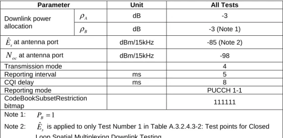
A.3.2.4 LTE / FTP Downlink / PDSCH Closed Loop Spatial Multiplexing Performance (Cell-Specific Reference Symbols) ... 65
A.3.2.4.1 Definition ... 65
A.3.2.4.2 Test Purpose ... 65
A.3.2.4.3 Test Parameters ... 65
A.3.2.4.4 Test Description ... 66
A.3.2.4.4.1 Initial Conditions ... 66
A.3.2.4.4.2 Procedure ... 66
A.3.2.5 LTE / FTP Downlink / PDSCH Single-layer Spatial Multiplexing Performance (Port 5, UE-Specific Reference Symbols) ... 67
A.3.2.5.1 Definition ... 67
A.3.2.5.2 Test Purpose ... 67
A.3.2.5.3 Test Parameters ... 67
A.3.2.5.4 Test Description ... 68
A.3.2.5.4.1 Initial Conditions ... 68
A.3.2.5.4.2 Procedure ... 68
A.3.2.6 LTE / FTP Downlink / PDSCH Single-layer Spatial Multiplexing Performance (Port 7 or 8, UE-Specific Reference Symbols) ... 69
A.3.2.6.1 Definition ... 69
A.3.2.6.2 Test Purpose ... 69
A.3.2.6.3 Test Parameters ... 69
A.3.2.6.4 Test Description ... 70
A.3.2.6.4.1 Initial Conditions ... 70
A.3.2.6.4.2 Procedure ... 70
A.3.2.7 LTE / FTP Downlink / PDSCH Dual-layer Spatial Multiplexing Performance (port 7 and 8, User-Specific Reference Symbols) ... 71
A.3.2.7.1 Definition ... 71
A.3.2.7.2 Test Purpose ... 71
A.3.2.7.3 Test Parameters ... 71
A.3.2.7.4 Test Description ... 72
A.3.2.7.4.1 Initial Conditions ... 72
A.3.2.7.4.2 Procedure ... 72
A.3.3 LTE / UDP Downlink Performance ... 73
A.3.3.1 LTE / UDP Downlink / PDSCH Single Antenna Port Performance (Cell-Specific Reference Symbols) ... 73
A.3.3.1.1 Definition ... 73
A.3.3.1.3 Test Parameters ... 73
A.3.3.1.4 Test Description ... 74
A.3.3.1.4.1 Initial Conditions ... 74
A.3.3.1.4.2 Procedure ... 74
A.3.3.2 LTE / UDP Downlink / PDSCH Transmit Diversity Performance (Cell-Specific Reference Symbols) .... 75
A.3.3.2.1 Definition ... 75
A.3.3.2.2 Test Purpose ... 75
A.3.3.2.3 Test Parameters ... 75
A.3.3.2.4 Test Description ... 76
A.3.3.2.4.1 Initial Conditions ... 76
A.3.3.2.4.2 Procedure ... 76
A.3.3.3 LTE / UDP Downlink / PDSCH Open Loop Spatial Multiplexing Performance (Cell-Specific Reference Symbols) ... 77
A.3.3.3.1 Definition ... 77
A.3.3.3.2 Test Purpose ... 77
A.3.3.3.3 Test Parameters ... 77
A.3.3.3.4 Test Description ... 78
A.3.3.3.4.1 Initial Conditions ... 78
A.3.3.3.4.2 Procedure ... 78
A.3.3.4 LTE / UDP Downlink / PDSCH Closed Loop Spatial Multiplexing Performance (Cell-Specific Reference Symbols) ... 79
A.3.3.4.1 Definition ... 79
A.3.3.4.2 Test Purpose ... 79
A.3.3.4.3 Test Parameters ... 79
A.3.3.4.4 Test Description ... 80
A.3.3.4.4.1 Initial Conditions ... 80
A.3.3.4.4.2 Procedure ... 80
A.3.3.5 LTE / UDP Downlink / PDSCH Single-layer Spatial Multiplexing Performance (port 5, User-Specific Reference Symbols) ... 81
A.3.3.5.1 Definition ... 81
A.3.3.5.2 Test Purpose ... 81
A.3.3.5.3 Test Parameters ... 81
A.3.3.5.4 Test Description ... 82
A.3.3.5.4.1 Initial Conditions ... 82
A.3.3.5.4.2 Procedure ... 82
A.3.3.6 LTE / UDP Downlink / PDSCH Single-layer Spatial Multiplexing Performance (Port 7 or 8, UE-Specific Reference Symbols) ... 83
A.3.3.6.1 Definition ... 83
A.3.3.6.2 Test Purpose ... 83
A.3.3.6.3 Test Parameters ... 83
A.3.3.6.4 Test Description ... 84
A.3.3.6.4.1 Initial Conditions ... 84
A.3.3.6.4.2 Procedure ... 84
A.3.3.7 LTE / UDP Downlink / PDSCH Dual-layer Spatial Multiplexing Performance (port 7 and 8, User-Specific Reference Symbols) ... 85
A.3.3.7.1 Definition ... 85
A.3.3.7.2 Test Purpose ... 85
A.3.3.7.3 Test Parameters ... 85
A.3.3.7.4 Test Description ... 86
A.3.3.7.4.1 Initial Conditions ... 86
A.3.3.7.4.2 Procedure ... 86
A.3.4 LTE / FTP Uplink Performance ... 87
A.3.4.1 LTE / FTP Uplink / PUSCH Single Antenna Port Performance ... 87
A.3.4.1.1 Definition ... 87
A.3.4.1.2 Test Purpose ... 87
A.3.4.1.3 Test Parameters ... 87
A.3.4.1.4 Test Description ... 87
A.3.4.1.4.1 Initial Conditions ... 87
A.3.4.1.4.2 Procedure ... 88
A.3.5 LTE / UDP Uplink Performance ... 88
A.3.5.1 LTE / UDP Uplink / PUSCH Single Antenna Port Performance ... 88
A.3.5.1.2 Test Purpose ... 88
A.3.5.1.3 Test Parameters ... 88
A.3.5.1.4 Test Description ... 89
A.3.5.1.4.1 Initial Conditions ... 89
A.3.5.1.4.2 Procedure ... 89
A.3.6 LTE / Stress Test Performance ... 90
A.3.6.1 LTE / Stress Test Performance / PDSCH Transmit Diversity Performance (Cell-Specific Reference Symbols) ... 90
A.3.6.1.1 Definition ... 90
A.3.6.1.2 Test Purpose ... 90
A.3.6.1.3 Test Parameters ... 90
A.3.6.1.4 Test Description ... 91
A.3.6.1.4.1 Initial Conditions ... 91
A.3.6.1.4.2 Procedure ... 91
A.3.6.2 LTE / Stress Test Performance / PDSCH Open Loop Spatial Multiplexing Performance (Cell-Specific Reference Symbols) ... 91
A.3.6.2.1 Definition ... 91
A.3.6.2.2 Test Purpose ... 91
A.3.6.2.3 Test Parameters ... 92
A.3.6.2.4 Test Description ... 92
A.3.6.2.4.1 Initial Conditions ... 92
A.3.6.2.4.2 Procedure ... 93
A.3.7 LTE / UDP Power Sweep Performance ... 93
A.3.7.1 LTE / UDP Power Sweep Performance / PDSCH Transmit Diversity Performance (Cell-Specific Reference Symbols) ... 93
A.3.7.1.1 Definition ... 93
A.3.7.1.2 Test Purpose ... 93
A.3.7.1.3 Test Parameters ... 93
A.3.7.1.4 Test Description ... 95
A.3.7.1.4.1 Initial Conditions ... 95
A.3.7.1.4.2 Procedure ... 95
A.3.7.2 LTE / UDP Power Sweep Performance / PDSCH Open Loop Spatial Multiplexing Performance (Cell-Specific Reference Symbols) ... 95
A.3.7.2.1 Definition ... 95
A.3.7.2.2 Test Purpose ... 95
A.3.7.2.3 Test Parameters ... 96
A.3.7.2.4 Test Description ... 97
A.3.7.2.4.1 Initial Conditions ... 97
A.3.7.2.4.2 Procedure ... 97
A.3.8 LTE / UDP Downlink vs. SNR Performance ... 97
A.3.8.1 LTE / UDP Downlink vs. SNR Performance / PDSCH Transmit Diversity Performance (Cell-Specific Reference Symbols) ... 97
A.3.8.1.1 Definition ... 97
A.3.8.1.2 Test Purpose ... 98
A.3.8.1.3 Test Parameters ... 98
A.3.8.1.4 Test Description ... 98
A.3.8.1.4.1 Initial Conditions ... 98
A.3.8.1.4.2 Procedure ... 99
A.3.8.2 LTE / UDP Downlink vs. SNR Performance / PDSCH Open Loop Spatial Multiplexing Performance (Cell-Specific Reference Symbols) ... 99
A.3.8.2.1 Definition ... 99
A.3.8.2.2 Test Purpose ... 99
A.3.8.2.3 Test Parameters ... 99
A.3.8.2.4 Test Description ... 101
A.3.8.2.4.1 Initial Conditions ... 101
A.3.8.2.4.2 Procedure ... 101
A.3.8.3 LTE / UDP Downlink vs. SNR Performance / PDSCH Closed Loop Spatial Multiplexing Performance (Cell-Specific Reference Symbols) ... 101
A.3.8.3.1 Definition ... 101
A.3.8.3.2 Test Purpose ... 101
A.3.8.3.3 Test Parameters ... 102
A.3.8.3.4.1 Initial Conditions ... 103
A.3.8.3.4.2 Procedure ... 103
A.3.8.4 LTE / UDP Downlink vs. SNR Performance / PDSCH Closed Loop Spatial Multiplexing using a single transmission layer Performance (Cell-Specific Reference Symbols) ... 103
A.3.8.4.1 Definition ... 103
A.3.8.4.2 Test Purpose ... 104
A.3.8.4.3 Test Parameters ... 104
A.3.8.4.4 Test Description ... 104
A.3.8.4.4.1 Initial Conditions ... 104
A.3.8.4.4.2 Procedure ... 105
Annex B:
Specific Test Conditions and Environment ... 106
B.0
Purpose of Annex ... 106
B.1 Reference
Test
Points
... 106
B.1.1 Reference Test Points for HSPA ... 106
B.1.2 Reference Test Points for LTE ... 107
B.2 Reference
system configurations ... 107
B.2.1 HSPA reference system configurations ... 107
B.2.1.1 Mapping of UE reported CQI and TBS (HSPA) ... 107
B.2.1.2 MAC Configurations ... 107
B.2.1.3 RLC Configuration ... 107
B.2.1.4 PDCP Configuration ... 108
B.2.2 LTE reference system configurations ... 108
B.2.2.1 Mapping of UE reported CQI and MCS (LTE) ... 108
B.2.2.2 MAC Configurations ... 114
B.2.2.3 RLC Configuration ... 115
B.2.2.4 PDCP Configuration ... 115
B.2.2.5 System Information... 115
B.2.2.6 Mapping of UE reported PMI ... 115
B.2.2.7 Mapping of UE reported RI ... 115
B.2.3 Network, Transport and Application Layers reference system configurations... 116
B.2.3.1 FTP Reference System Configuration ... 116
B.2.3.2 UDP Reference System Configuration ... 117
B.3
Recommendation for Operating band and Channel Bandwidth selection for application layer data
throughput measurements... 117
Annex C:
Specific Connection Diagrams ... 119
C.1 Purpose
of
annex
... 119
C.2
UE Application Layer Data Throughput Connection Diagrams ... 119
C.2.1 UE Application Layer Data Throughput Connection Diagram for Tethered ... 119
C.2.2 UE Application Layer Data Throughput Connection Diagram for Embedded... 119
Annex D:
Applicability ... 121
D.1 Purpose of annex ... 121
D.2 Recommended Test Case Applicability ... 121
D.3 ICS / IXIT proforma ... 127
D.3.1 General ... 127
D.3.1.1 Introduction ... 127
D.3.1.2 Abbreviations and conventions ... 127
D.3.1.3 Instructions for completing the ICS proforma... 127
D.3.2 Identification of the protocol ... 128
D.3.3 ICS proforma tables ... 128
D.3.3.1 UE Implementation Types ... 128
D.3.3.2 UE UTRA related capabilities... 128
D.3.3.3 UE E-UTRA related capabilities ... 129
D.3.4 IXIT proforma tables ... 130
Annex E:
Embedded Data Client Automation Recommendations... 132
E.1 Purpose
of
annex
... 132
E.2
Embedded Data Client Automation... 132
E.2.1 Embedded Data Client Functionality ... 132
E.2.2 Embedded Data Client Provisioning ... 132
E.2.3 Embedded Data Client Command Set and Operation ... 133
E.2.3.1 Poll for Task Command ... 133
E.2.3.2 Task List 133 E.2.3.3 Result Reporting ... 133
Annex F:
Change history ... 134
Foreword
This Technical Report has been produced by the 3rd Generation Partnership Project (3GPP).
The contents of the present document are subject to continuing work within the TSG and may change following formal TSG approval. Should the TSG modify the contents of the present document, it will be re-released by the TSG with an identifying change of release date and an increase in version number as follows:
Version x.y.z where:
x the first digit:
1 presented to TSG for information; 2 presented to TSG for approval;
3 or greater indicates TSG approved document under change control.
y the second digit is incremented for all changes of substance, i.e. technical enhancements, corrections, updates, etc.
1 Scope
The present document contains the findings of the Study Item on UE Application Layer Data Throughput Performance and the proposed test procedures.
2 References
The following documents contain provisions which, through reference in this text, constitute provisions of the present document.
- References are either specific (identified by date of publication, edition number, version number, etc.) or non-specific.
- For a specific reference, subsequent revisions do not apply.
- For a non-specific reference, the latest version applies. In the case of a reference to a 3GPP document (including a GSM document), a non-specific reference implicitly refers to the latest version of that document in the same Release as the present document.
[1] 3GPP TR 21.905: "Vocabulary for 3GPP Specifications".
[2] 3GPP TS 36.521-1: "Evolved Universal Terrestrial Radio Access (E-UTRA); User Equipment (UE) conformance specification Radio transmission and reception Part 1: Conformance Testing". [3] 3GPP TS 34.121-1: "User Equipment (UE) conformance specification; Radio transmission and
reception (FDD); Part 1: Conformance specification".
[4] 3GPP TS 34.122: "Terminal conformance specification; Radio transmission and reception (TDD)".
[5] 3GPP TS 34.123-1: "User Equipment (UE) conformance specification; Part 1: Protocol conformance specification".
[6] 3GPP TS 25.214: "Physical layer procedures (FDD)". [7] 3GPP TS 25.224: "Physical Layer Procedures (TDD)".
[8] 3GPP TS 33.401: "3GPP System Architecture Evolution (SAE): Security architecture". [9] 3GPP TS 36.211: "Physical Channels and Modulation".
[10] 3GPP TS 36.213: "E-UTRA Physical layer procedures".
[11] 3GPP TS 36.508: “Common test environments for User Equipment (UE)". [12] 3GPP TS 25.101: "UE Radio transmission and reception (FDD)".
[13] 3GPP TS 36.101: "E-UTRA UE radio transmission and reception".
[14] 3GPP TS 34.108: "Common Test Environments for User Equipment (UE) Conformance Testing". [15] L. J. Greenstein, V. Erceg, Y. S. Yeh, and M. V. Clark, “A new path-gain/delay-spread
propagation model for digital cellular channels”, IEEE Trans. on Vehicular Technology, Vol. 46, No. 2, May 1997, pp. 477-485.
3
Definitions, symbols and abbreviations
3.1 Definitions
For the purposes of the present document, the terms and definitions given in TR 21.905 [1] and the following apply. A term defined in the present document takes precedence over the definition of the same term, if any, in TR 21.905 [1]. idle mode: In this mode, the mobile station is not allocated any dedicated channel; it listens to the CCCH and the BCCH;
dedicated mode: In this mode, the mobile station is allocated at least two dedicated channels, only one of them being a SACCH;
packet idle mode: (only applicable for mobile stations supporting GPRS) In this mode, mobile station is not allocated any radio resource on a packet data physical channel; it listens to the PBCCH and PCCCH or, if those are not provided by the network, to the BCCH and the CCCH, see 3GPP TS 44.060 [76].
packet transfer mode: (only applicable for mobile stations supporting GPRS) In this mode, the mobile station is allocated radio resource on one or more packet data physical channels for the transfer of LLC PDUs.
GPRS: Packet Services for systems which operate the Gb or Iu-PS interfaces.
A default PDP context is a PDP context activated by the PDP context activation procedure that establishes a PDN connection. The default PDP context remains active during the lifetime of the PDN connection.
SIM, Subscriber Identity Module (see 3GPP TS 42.017 [7]).
USIM, Universal Subscriber Identity Module (see 3GPP TS 21.111 [101]).
PDN Connection: The association between a UE represented by one IPv4 address and/or one IPv6 prefix and a PDN represented by an APN.
Default APN: A Default APN is defined as the APN which is marked as default in the subscription data and used during the Attach procedure and the UE requested PDN connectivity procedure when no APN is provided by the UE. Dedicated bearer: An EPS bearer that is associated with uplink packet filters in the UE and downlink packet filters in the PDN GW where the filters only match certain packets. Definition derived from 3GPP TS 23.401 [10].
Default bearer: An EPS bearer that gets established with every new PDN connection. Its context remains established throughout the lifetime of that PDN connection. A default EPS bearer is a non-GBR bearer. Definition derived from 3GPP TS 23.401 [10].
EMM context: An EMM context is established in the UE and the MME when an attach procedure is successfully completed.
EMM-CONNECTED mode: A UE is in EMM-CONNECTED mode when a NAS signalling connection between UE and network is established. The term EMM-CONNECTED mode used in the present document corresponds to the term ECM-CONNECTED state used in 3GPP TS 23.401 [10].
EMM-IDLE mode: A UE is in EMM-IDLE mode when no NAS signalling connection between UE and network exists. The term EMM-IDLE mode used in the present document corresponds to the term ECM-IDLE state used in 3GPP TS 23.401 [10].
PDN address: an IP address assigned to the UE by the Packet Data Network Gateway (PDN GW).
Channel bandwidth: The RF bandwidth supporting a single E-UTRA RF carrier with the transmission bandwidth configured in the uplink or downlink of a cell. The channel bandwidth is measured in MHz and is used as a reference for transmitter and receiver RF requirements.
User Equipment: Mobile Equipment with one or several UMTS Subscriber Identity Module(s)
A device allowing a user access to network services via the Uu interface. The UE is defined in ref. TS 23.101 [8]. If this term is used in the context of Iur-g, it means MS in case it uses radio resources of a DBSS.
3.2 Symbols
For the purposes of the present document, the following symbols apply:
s
Eˆ
The received energy per RE of the wanted signal during the useful part of the symbol, i.e. excluding the cyclic prefix, averaged across the allocated RB(s) (average power within the allocated RB(s), divided by the number of RE within this allocation, and normalized to the subcarrier spacing) at the UE antenna connectoroc
N
The power spectral density of a white noise source (average power per RE normalised to the subcarrier spacing), simulating interference from cells that are not defined in a test procedure, as measured at the UE antenna connector NOffs-DL Offset used for calculating downlink EARFCNNOffs-UL Offset used for calculating uplink EARFCN
3.3 Abbreviations
For the purposes of the present document, the abbreviations given in TR 21.905 [1] and the following apply. An abbreviation defined in the present document takes precedence over the definition of the same abbreviation, if any, in TR 21.905 [1].
ACK Acknowledgement AES Advanced Encryption Standard
AM Acknowledged Mode
AMBR Aggregate Maximum Bit Rate
A-MPR Additional Maximum Power Reduction
APN Access Point Name
APN-AMBR APN Aggregate Maximum Bit Rate ARP Allocation Retention Priority ARQ Automatic Repeat Request AWGN Additive White Gaussian Noise BDP Bandwidth Delay Product BLER Block Error Rate
BS Base Station
CAT Category
C/I Carrier-to-Interference Power Ratio
CP Cyclic Prefix
C-plane Control Plane
CQI Channel Quality Indicator CRC Cyclic Redundancy Check
C-RNTI Cell RNTI
DCH Dedicated Channel
DCCH Dedicated Control Channel DL Downlink
DL TFT DownLink Traffic Flow Template
DRB Data Radio Bearer
DRX Discontinuous Reception
DTCH Dedicated Traffic Channel
DTX Discontinuous Transmission
EDGE Enhanced Data rates for Global Evolution
eNB E-UTRAN NodeB
EMM EPS Mobility Management
EPC Evolved Packet Core Network EPS Evolved Packet System ETU Extended Typical Urban
E-UTRA Evolved UMTS Terrestrial Radio Access
EUTRAN Evolved UMTS Terrestrial Radio Access Network
EVA Extended Vehicular A
EVM Error Vector Magnitude FDD Frequency Division Duplex FDM Frequency Division Multiplexing
FFS For Further Study FTP File Transfer Protocol GBR Guaranteed Bit Rate GCF Global Certification Forum
GERAN GSM EDGE Radio Access Network GSM Global System for Mobile Communications
HARQ Hybrid ARQ
HSDPA High Speed Downlink Packet Access
HS-DPCCH High Speed-Dedicated Physical Control Channel HS-PDSCH High Speed-Physical Downlink Shared Channel HS-SCCH High Speed-Shared Control Channel
HTTP Hypertext Transfer Protocol
IP Internet Protocol
IPv4 Internet Protocol, version 4 IPv6 Internet Protocol, version 6 ISD Inter Site Distance
kbps Kilobits per second
LNA Low Noise Amplifier
LTE Long Term Evolution (common expression, in other 3GPP specifications defined as EUTRA and EPC)
MAC Medium Access Control
Mbps Megabits per second
MBR Maximum Bit Rate
MCS Modulation and Coding Scheme MIMO Multiple Input Multiple Output MTU Maximum Transmission Unit
NACK Negative Acknowledgement
NIC Network Interface Connection
OFDM Orthogonal Frequency Division Multiplexing
PA Power Amplifier
PA Pedestrian A (Fading model, depending on context)
PB Pedestrian B
PBCH Physical Broadcast Channel PDCP Packet Data Convergence Protocol PDCCH Physical Downlink Control Channel PDSCH Physical Downlink Shared Channel PDU Protocol Data Unit
PHY Physical layer
QAM Quadrature Amplitude Modulation
QCI QoS Class Identifier QoS Quality of Service
QPSK Quadrature Phase Shift Keying RAB Radio Access Bearer
RAT Radio Access Technology
RB Radio Bearer
RF Radio Frequency
RLC Radio Link Control
RNTI Radio Network Temporary Identity
RMC Reference Measurement Channel
RRC Radio Resource Control RTP Real-Time Transport Protocol
RTT Round Trip Time
SFTP SecureFile Transfer Protocol SIMO Single Input Multiple Output
SNR Signal-to-Noise Ratio
SS System Simulator
TB Transport Block
TBS Transport Block Size
TCP Transmission Control Protocol
TDD Time Division Duplex TFT Traffic Flow Template TFTP Trivial File Transfer Protocol
TM Transparent Mode TTI Transmission Time Interval UDP User Datagram Protocol
UE User Equipment
UL Uplink
UM Unacknowledged Mode
UMTS Universal Mobile Telecommunications System UTRA UMTS Terrestrial Radio Access
UTRAN UMTS Terrestrial Radio Access Network USB Universal Serial Bus
USIM UMTS Subscriber Identity Module
VoIP Voice over IP
4 Background
The currently-used HSPA and the newly-deployed LTE radio access technologies are providing a very large increase in data transmission capacity in mobile networks. This is being matched and even exceeded by a corresponding increase in the demand for data from users of the latest data-hungry devices and applications.
It is therefore essential that data devices achieve high efficiency when using data services and do not unduly load the network regardless of the maximum data rate that they are capable of achieving.
The GCF has indicated that they wish to add UE Application-Layer Data Throughput Measurements under various simulated network conditions to their Performance Items area of activity and has requested RAN5 to recommend and produce the necessary test procedures. It is also noted that the PTCRB, TCG might additionally be able to take advantage of the results of such work in 3GPP.
4.1 Study
Item
Objective
The objective of this Study Item is to define test procedures to measure UE data throughput performance at the application-layer, with no qualification of the results (i.e. no verdicts such as "pass/fail", "good", "medium", "bad" will be supplied).
The test procedures developed will measure the achieved average application-layer data rates (e.g. using FTP or UDP) of the UE standalone or/and in combination with a laptop under simulated realistic network scheduling and radio conditions in a repeatable lab-based environment (i.e. using lab-based simulators and other necessary equipment).
Note: The point of measurement on the UE side will be either in a connected PC for terminals that support tethered mode only, or inside the UE in case of a terminal that does not support tethered mode, or in both places for UEs that support both modes.
The test procedures will be developed in a flexible manner to accommodate various test conditions. The exact simulated network scheduling and down link radio conditions to be used will be determined during the study. It is envisaged that in addition to some measurements under "ideal conditions", an initial set of suitable scheduling/radio conditions to be used by the test systems, will be defined to simulate typical network conditions. Additional optional conditions may be developed later as and when required.
The study will aim to reuse wherever possible conditions already specified by RAN4 (e.g. radio conditions) and test procedures used in current conformance testing by RAN5. Although utilising existing test procedures without any modification is unlikely, adaptation of existing test cases may well be possible. The study should determine the best candidates.
Note: Test cases for example in clause 8 of TS 36.521-1 [2] could possibly be adapted for the study and test procedures could be based on the existing single antenna port, transmit diversity, and open and closed loop spatial multiplexing test cases.
The study will determine suitable test procedures for downlink data transfers, uplink data transfers and bidirectional data transfers.
The study will determine the Applications and the related Application requirements (e.g. FTP, UDP, quality of service, TCP settings, etc.) to be used.
GCF has stated that the Radio connection should be limited to LTE and W-CDMA Rel-5 (HSDPA) and later and the study will only consider these.
Other issues that the Study Item may investigate include:
- The definition of a reliable and repeatable test environment to ensure the best possible repeatability of the results. This could include the definition of a reference laptop configuration, applications in the UE or/and the Laptop that would measure the throughput, etc.
- The impact from the lower layers data throughput on the application-layer data throughput, especially when variable radio conditions are applied.
5
Study of UE Application Layer Data Throughput
Performance
5.1
Definition of UE Application Layer Data Throughput
Performance
5.1.1
Definition of End Points
For tethered connections, the UE is tethered to a laptop using the appropriate UE to PC interface Modem or Network Interface Connection (NIC) drivers as recommended by the UE manufacturer for the intended use by the customer/user. In most cases, a laptop with an embedded modem is considered to be a tethered data configuration as opposed to an embedded data configuration due to the UE to PC interface.
For tethered connections, the end points are the application running on the PC connected to the UE and a corresponding Data Server that is adjacent to the simulated lab-based Core Network. In this case, the PC drivers (typically USB) will also play a role in the UE Application Layer Data Throughput performance.
For non-tethered connections as in the case of embedded applications or applications running on the UE itself, the end points are the application running on the UE and a corresponding Data Server that is adjacent to the simulated lab-based Core Network.
5.1.2
Definition of UE Application Layer Data Throughput
The measured UE Application Layer Throughput, T, is defined as the number of useful user data bits per unit of time delivered by the network from the source end point to the destination end point, excluding protocol overhead (TCP header, UDP header, etc.) and retransmitted data packets. The end points are defined in clause 5.1.1.
5.2 Parameters
for
Measurement
5.2.1 Throughput
The UE Application Layer Data Throughput as defined in clause 5.1.2 shall be a parameter for measurement. The parameter would apply for any chosen application. The throughput can be measured in each direction (downlink and uplink).
5.3 Test
Configurations
5.3.1
UE Application Layer Data Throughput Test Equipment
The test equipment utilized for UE Application Layer Data Throughput shall consistent of the following items. Some of the elements below may be implemented in the same piece of test equipment depending on implementation.
- UE
- For tethered mode operation, Laptop/PC and appropriate UE to PC interface Modem or Network Interface Connection (NIC) drivers and any associated cabling as recommended by the UE manufacturer for the intended use by the customer/user
- Data client test application for the PC for tethered mode operation - Data client test application(s) for the UE for embedded mode operation
- System Simulator(s) suitable for the radio technology(s) used for testing with necessary IP connectivity - Application Servers
- Faders and AWGN Sources capable of supporting the radio environments defined
5.3.2
UE Application Layer Data Throughput Connection Diagrams
5.3.2.1
UE Application Layer Data Throughput Connection Diagram for Tethered
The UE Application Layer Data Throughput connection diagram for tethered operation is shown in Figure C.2.1-1.
5.3.2.2
UE Application Layer Data Throughput Connection Diagram for Embedded
The UE Application Layer Data Throughput connection diagram for embedded operation is shown in Figure C.2.2-1.
5.3.3
RF Connection Diagrams for UE Application Layer Data Throughput
The RF connections between the SS and the UE shall be in compliance with the associated RF connection diagrams specified in the test procedure clauses in Annex A. As the RF connection diagrams vary based on device type and UE category, it is preferable to reference appropriate RF connection diagrams for similar test configurations in the core test specifications. The RF connection diagrams are to be based on the representative RF connection diagrams referenced in 36.521-1 [2], 34.121-1 [3], or 34.122 [4].
5.3.4
UE Specific Items
There are no UE specific items identified at this time that are required to support the UE Application Layer Data Throughput testing herein.
5.3.5 Reference
Laptop
The reference laptop should be used in the tethered connections as defined in sub-clause 5.1.1. It is necessary to specify drivers and electronic characteristics of hardware interface (typically power and ground noise) in the UE Application Layer Data Throughput performance. The physical interface towards the UE may be for example a standard USB interface. Other interfaces of proprietary or standardized type shall not be precluded. The laptop should be equipped with the appropriate processing power in order to support high data rates. The laptop should be “Stand Alone” and not embedded in any network, for example company network. The laptop configuration, including hardware and software is subject to change in order to follow the latest development in the market.
The laptop should not be equipped with SW that influences the data transfer. The laptop should be configured with standard modem driver or driver provided by the UE manufacturer.
5.4
Transport and Application Layer Protocols
5.4.1
Transport Layer Protocol
For the transport layer protocol, TCP and UDP are considered. It is proposed to test with both TCP and UDP as measurements utilizing each transport protocol are relevant.
The following items highlight the need for TCP transport.
- Most of the applications that need reliable data transfers use TCP as transport layer. - The throughput is sensitive to the end-to-end delay.
- Good for testing FTP/HTTP in bi-directional tests in asymmetric data rate links because the downlink speeds are limited by uplink speeds. For FTP/HTTP data transfers in one direction, the TCP ACKs are transmitted in the other direction, therefore delay in receiving TCP ACK in one direction negatively impacts FTP/HTTP throughput in the other direction.
The following items highlight the need for UDP transport.
- The performance of UDP based data transfer, unlike TCP based transfer, is Operating System agnostic - Real-Time Transport Protocols used by most of Multi Media Applications are based on UDP protocol. - UDP Data Transfer in one direction (uplink/downlink) is not dependent on the other direction characteristics,
unlike with TCP.
5.4.2
Application Layer Protocol
The following items have been considered for appropriate application layer protocols that utilize TCP as a transport protocol. - FTP - TFTP - SFTP - HTTP - VoIP (RTP-based)
To reduce the amount of testing, it is proposed to use FTP only. FTP (File Transfer Protocol) runs on top of TCP/IP and is frequently used in applications where download/upload performance would be noticeable to the end user.
The following list identifies the reasons not to duplicate testing across the other application layer protocols.
- SFTP and HTTP both use TCP as a transport protocol. So it is redundant to use HTTP/SFTP protocols to test data throughput when FTP protocol is used.
- For test purposes, HTTP is typically used to benchmark the browser’s rendering capabilities as a functional test. Download performance in terms of relative throughput is not as noticeable to the end user as it would be for file downloads.
- SFTP is process intensive and used to exercise the security engine within the UE.
- TFTP is typically used in embedded devices to update the firmware in a reliable way using a low footprint stack to avoid using the full TCP stack. TFTP is a request-response protocol and is not a candidate for performance analysis.
- VoIP (RTP-based) applications are diverse in nature and application compatibility is an issue for a standard set of UE Application Layer Data Throughput Performance test procedures.
For UDP, it is proposed to use raw data transfer as opposed to defining a streaming protocol to simplify the UDP transfer application requirements.
5.4.2.1 FTP
Settings
It is recommended that the FTP server used for testing meet the following requirements:
- The TCP send/receive buffer sizes at the FTP server should be set to values sufficiently large to ensure they do not limit the maximum throughput achievable at the UE
- The tx queue length should be set to a value sufficiently large value to ensure flow control between the network interface (ppp) and TCP is not triggered
It is recommended that the FTP application used on the tethered PC for tethered testing meet the following requirements:
- The tethered FTP application should allow the user to transfer files of any format supported by the tethered PC, in binary mode, in both the Downlink and the Uplink
- The tethered FTP application should provide the means to compute the throughput T as defined in subclause 5.1.2 at the end of each file transfer
- The tethered FTP application should provide an interface allowing automation of testing
- The tethered FTP application t should not implement hidden optimizations that might impact the throughput An example of an FTP application meeting these requirements is the Windows FTP command line application. This example is cited for information only and does not in any way preclude the use of other applications meeting the recommended requirements.
For embedded testing, the FTP client will reside in the UE under test. This will require an FTP application to be installed on the UE. It is recommended that this application meet the following requirements:
- The embedded FTP application should allow the user to transfer files of formats supported by the UE, in binary mode, both in the Downlink and the Uplink.
- The embedded FTP application should provide the means to compute the throughput T as defined in subclause 5.1.2 at the end of each file transfer.
- The embedded FTP application should provide an interface allowing automation of testing. If an interface for automation of testing is implemented, it is recommended to use the embedded data client automation
recommendations in Annex E.
- The embedded FTP application should not implement hidden optimizations that might impact the throughput. The following settings are to be used.
- The TCPWindowSize is derived based on the bandwidth-delay product (BDP) for the particular radio access bearer used in the test. Refer to clause 5.4.2.1.1 for guidance concerning the TCP advertised receiver window size setting.
- The TCPWindowSize is adjusted to near even-multiple of TCP MTU. The Windows Scaling is enabled for all FTP transfers.
- The socket buffer sizes are set to even-multiples of TCP MTU in use and set to values equal or greater than the BDP.
- The TCP MTU size is set to a value comprised between 1280 and 1500 bytes as recommended by the manufacturer.
- The FTP transfers are always carried out in Binary mode.
- The contents of the files to be transferred over FTP are chosen in such a way that they are statistically random, with least compressibility.
- No application level compression protocols are used to compress the FTP files.
- Either IPv4 or IPv6 can be used, but only results obtained with the same IP address type can be compared, since the IP address type will affect the measured throughput.
5.4.2.1.1
TCP advertised receiver window size setting
In order to achieve maximum throughput during FTP testing, the TCP advertised receiver window size must be equal to or greater than the BDP (Bandwidth Delay Product), which can be expressed as follows:
Where:
TCP data rate is the portion of the radio bearer used to send TCP data
RTT is the unloaded Round Trip Time between TCP end-points (FTP server and tethered laptop/embedded FTP app) as seen by the TCP sender.
Note that the TCP data rate and the RTT may be different for different test procedures.
5.4.2.2 UDP
Settings
It is recommended that the UDP server used for testing meet the following requirements:
- UDP blast duration shall be selected to meet the minimum test times using a sufficient rate to prevent physical layer DTX based upon the UE Category.
It is recommended that the UDP application used on the tethered PC for tethered testing meet the following requirements:
- The tethered UDP application should allow the user to transfer files of any format supported by the tethered PC, in binary mode, in both the Downlink and the Uplink.
- The tethered UDP application should provide the means to compute the throughput T as defined in subclause 5.1.2.
- The tethered UDP application should provide an interface allowing automation of testing.
- The tethered UDP application should not implement hidden optimizations that might impact the throughput. For embedded testing, the UDP client will reside in the UE under test. This will require an UDP application to be installed on the UE. It is recommended that this application meet the following requirements:
- The embedded UDP application should allow the user to transfer files of formats supported by the UE, in binary mode, both in the Downlink and the Uplink.
- The embedded UDP application should provide the means to compute the throughput T as defined in subclause 5.1.2.
- The embedded UDP application should provide an interface allowing automation of testing. If an interface for automation of testing is implemented, it is recommended to use the embedded data client automation
recommendations in Annex E.
- The embedded UDP application should not implement hidden optimizations that might impact the throughput. The following settings are to be used.
- The UDP MTU size is set to a value comprised between 1280 and 1500 bytes as recommended by the manufacturer.
- The UDP transfers are always carried out in Binary mode.
- The contents of the files to be transferred over UDP are chosen in such a way that they are statistically random, with least compressibility.
- No application level compression protocols are used to compress the UDP files..
- Either IPv4 or IPv6 can be used, but only results obtained with the same IP address type can be compared, since the IP address type will affect the measured throughput.
5.5 Test
Environment
Editor’s Note: As per RAN4 recommendations, Recommendation #4 as stated in response LS R4-122042, RAN 5 is investigating the possibility to add multicell scenario’s in to the TR.
5.5.1 Signal
Levels
The signal levels chosen for test should either be representative of field conditions or appropriate for the test purpose of the particular test procedure defined.
In order to optimize test time and to focus on the appropriate set of signal levels for test, it is proposed to leverage the signal levels for test associated with the associated performance test cases in 34.121-1 [3], 34.122 [4], and 36.521-1 [2] or to limit the number of signal levels for the majority of the downlink performance tests to a representative range. For test cases that would require specific geometries to be set, this approach is reasonable and allows as much re-use of existing test setups as possible.
However, one aspect of a receiver's performance that is not typically addressed in the conformance testing is the ability of the receiver to perform well across a range of signal levels in a relatively low-noise environment where the UE noise floor may be the dominant factor in determining SNR. The end user would expect the UE Application Layer Data Throughput to increase as the signal level is increased in relation to the UE noise floor or to achieve relatively
consistent UE Application Layer Data Throughput if located in a sufficient signal strength area such that the throughput has reached a maximum. However, it has been shown across different radio designs that the data performance can vary significantly due to LNA switch points which may impact the perceived SNR to the modem and thus impacting the end user perception of throughput performance even in a strong signal environment. Therefore, it is proposed to use a power sweep test to characterize the UE performance within a limited range of power levels. Also, in order to exercise the hysteresis associated with the LNA switch points under realistic RF conditions, it is proposed to make use of a vehicular fading profile from 34.121-1 [3], 34.122 [4], and 36.521-1 [2].
By addressing the power sweep test in the UE Application Layer Data Throughput performance testing, one achieves the ability to evaluate the impact of this receiver aspect and its impact at the user level without impacting the industry conformance test cases. For LTE, typical transmission modes that would be used in operation based on the downlink signal level presented to the UE should also be considered.
5.5.2 Fading
Profiles
The request from the GCF Steering Group was to measure the average UE Application Layer Data Throughput using simulated realistic radio conditions. In order to support this requirement, it is proposed to consider the following fading profiles to maintain consistency with 3GPP defined fading profiles that have been developed to assess a UE's capability of performing in various multi-path environments. Also, a static propagation condition should be considered for any uplink testing and any downlink performance testing where the test purpose does not specifically require fading (e.g. maximum throughput testing, stress testing where the focus is on processor utilization aspects, etc.).
For HSPA, the following defined 3GPP profiles have been considered depending on the particular test procedure. - Static - PB3 - PA3 - VA3 - VA30 - VA120
For LTE, the following defined 3GPP profiles have been considered depending on the particular test procedure. - Static - EPA5 - EVA5 - EVA70 - EVA200 - ETU70
- ETU300 - HST
See clause 5.5.4.5 for the conclusion of selected fading profiles to be used for UE application layer data throughput measurements.
5.5.3
Noise and Interference Levels
In order to assess the end user perception of UE Application Layer Data Throughput, it is desirable to vary Ior/Ioc over a range of values that are representative of the majority of the conditions experienced by the end user. It is also desirable to utilize very high SNR cases for maximum data rate testing or for high order modulation testing. The range of values chosen should either match existing performance test cases in 3GPP or represent a reasonable number of discrete SNR values for test with the exception of any test procedure where the test purpose is to evaluate the
throughput performance versus geometry. In this case, the step size for the SNR values should be chosen appropriately. See clause 5.5.4.5 for the conclusion of selected noise and interference levels to be used for UE application layer data throughput measurements.
5.5.4 Selection
of
combinations
of Fading Profiles and Noise and
Interference Levels
5.5.4.1 General
The objective of the study item is to define testing procedures to measure the UE data throughput at the application layer and give an assessment on the data-rate variation with various levels of fading and speed profiles. The throughput at a UE application level includes the combined performance of the
1. Radio link RF performance
2. Radio link protocol data processing performance (MAC, RLC, PDCP) 3. TCP/IP processing performance
4. Internet Application and driver process performance
The radio link performance is thoroughly tested in TS 34.121-1 [3] /TS 34.122[4]/ TS 36.521-1 [2] under various propagation conditions, but the higher layer performance is not. The selection of test points should thus be taken from the upper-layer perspective, while keeping the assessment of the actual data-rate variations of different implementations in mind. This is consistent with the justification of the study item
“The proposed Work Item will define test procedures to measure the data throughput under various network conditions that will provide absolute measured results as evidence that, even with an excellent radio connection or optimised equaliser, the net data rate is not reduced due to, for example, a non-optimised software architecture or sup-optimal components in the device. Furthermore unsuitable drivers connecting the Data device with a PC could have also a negative impact on the measured data throughput rate.”
that address finding evidence of bottlenecks in the protocol stack limiting the application layer throughput. This requires that the physical-layer test conditions are chosen so that relevant mechanisms of the higher-layers are triggered.
5.5.4.2
Lower-layer (PHY) testing
The physical layer is thoroughly tested in TS 34.121-1 [3]/ TS 34.122 [4]/ TS 36.521-1 [2] and dominates the end-to-end performance as discussed in clause 5.8. In order to avoid duplication of tests, the aim should not be to go through all the existing tests and configurations.
In clause 5.8 it is proposed to consider application-layer performance tests measuring higher layer throughput in noise-free non fading single-path conditions suggesting such tests are the best in revealing higher layer UE bugs affecting throughput. The static and noise-free scenario is certainly one possible test condition, but in order to make sure the entire protocol stack is tested with regard to implementation errors and mismatch under transport block size variability and fast variations similar to what occurs in e.g. the field tests under live conditions, relevant fading scenarios that trigger these variations should also be included. This will not only complement the higher-layer tests in TS 34.123-1 [5]
(UTRA) and TS 36.523-1 (E-UTRA) performed under ideal radio conditions, but also meet the objective of providing an assessment of the UE data-rate variations with various fading- and speed profiles.
5.5.4.3
Higher-layer impact on application layer throughput
Table 5.5.4.3-1 shows the test aspects that should be considered in addition to the static and noise-free scenario for some selected HSPA and LTE scenarios to check that upper-layers do not constrain (often by errors or mismatch) the throughput under dynamic the channel conditions as experienced in field (drive) tests. The application and associated channel profiles and geometries are just examples.
The dynamic conditions can trigger undesired behaviours of the upper-layers not covered in the signalling tests, e.g. when RLC retransmissions occur or being caused.
Table 5.5.4.3-1: Aspects covered for identifying high-layer performance
Conditions Test aspect
HSPA, Download UDP/FTP Throughput, follow-CQI,
PA3, Geometry = 10dB Big TBS variations HSPA, Download UDP/FTP Throughput, follow-CQI,
VA30, Geometry = 10dB Fast variations HSPA, Download UDP/FTP Throughput, follow-CQI,
VA120, Geometry = 0dB High BLER and fast variations HSPA, Bi-Directional UDP/FTP Throughput, follow-CQI,
Static, Geometry = 20 dB Processing capability HSPA Cat8, Bi-Directional FTP Throughput, AMR Multi
RAB, follow-CQI, Static, Geometry = 20 dB Processing capability LTE, Download UDP/FTP Throughput, follow-CQI sub
band reporting, EPA3, SNR = 20dB Big TBS variations LTE, Download UDP/FTP Throughput, follow-CQI sub
band reporting ETU70, SNR = 0dB Fast variations LTE, Download UDP/FTP Throughput, follow-CQI
wideband reporting, ETU300, SNR = 0dB High BLER and fast variations LTE, Download UDP/FTP Throughput, follow-CQI
wideband reporting, Static, SNR = 20dB Processing capability LTE, Bi-Directional FTP Throughput, follow-CQI
wideband reporting, Static, SNR = 20dB Processing capability
Figure 5.5.4.3-1 shows the variation of the reported CQI (TBS) and the time-variability of some of the propagation conditions typically used in the radio-link test cases.
Figure 5.5.4.3-1: TBS- and time variability for various propagation conditions.
The PA channel gives rise to larger TBS variations than the more dispersive VA and PB channels. This is due to the wide-sense stationary uncorrelated channels used, in which the likelihood that the single dominant tap in the PA model experiences a fading dip is larger than the likelihood that the taps in the dispersive models will experience fading dips simultaneously. The SNR and wanted-signal variability tracked by the CSI reporting is therefore smaller for the latter channels.
Higher geometries will allow larger TBS and MCS variations and verification of the processing capabilities at good radio conditions. For lower geometries and high speed the BLER is typically high such as under the VA120 at 0 dB geometry.
To pick relevant propagation conditions, then scenarios that users typically experience and that also challenge the upper layers should be selected.
5.5.4.4
Typical physical parameters for verifying higher-layer impact
The typical physical parameters should be chosen to trigger mechanisms in the higher layers whilst finding relevant conditions for assessment of UE performance beyond PASS/FAIL.
The empirical Greenstein model [15] has constituted the basis for many models including the 3GPP/3GPP2 spatial channel model described in TR 25.996. The path gain and delay spread follow [15] with the shadow correlated with the delay spread, and assuming uncorrelated shadowing between sites. The geometry (C/I) is the ratio between the path gain from best site and sum of path gains from all other sites. 100 sites has been laid out at various ISD (inter-site distance) assuming and urban, sub-urban and rural scenario.
Figures 5.5.4.4-1 and 5.5.4.4-2 show the results for urban environment with ISD = 0.5 km and 3 km, respectively. The CDF curves display the cumulative distribution of the delay spread conditioned on a certain range of C/I.
Figure 5.5.4.4-1: Urban environment with small microcells
Figure 5.5.4.4-2: Urban environment with microcells
The delay spread of the Pedestrian A (PA), Pedestrian B (PB), Vehicular A (VA) and Typical Urban (TU) are 0.05 μs, 0.75 μs, 0.37 μs and 1 μs, respectively. The results in Figure 5.5.4.4-1 indicate that 0.02% of all users have a C/I > 20 dB and a delay spread larger or equal to that of VA, while 0.2% has C/I > 10 dB and a delay spread larger or equal to that of VA. The corresponding results for the larger microcells are 1% with C/I > 20 dB and 8% with C/I > 10 dB. It appears that the typical urban is not very typical (it was developed in early GSM days with very large cells), and we note that only 1% has C/I > 0 dB and a more dispersive profile than PB.
The results from the sub-urban and rural scenarios are shown in Figure 5.5.4.4-3. It can be observed that 0.4% of all users have C/I > 20 dB and a delay spread larger or equal to that of VA for the sub-urban, while 0.1% of all users in rural macro cells have C/I > 0 dB and a delay spread of 0.5 μs or larger.
Figure 5.5.4.4-3: Fraction of users with a certain delay spread and geometry for sub-urban (left) and rural (right)
The simulations have some weak points: BS antenna tilt has not been considered and the Greenstein model from 1994 may be slightly outdated considering more recent network deployments. However, a comparison with measured results taken in Atlanta, GA, reveals that there is good agreement between measurements and simulations. The measurements are car-based with a test terminal inside the vehicle, and with routes covering urban, suburban and highways. From Figure 5.5.4.4-4 we note that 0.2% of all locations have a C/I > 20 dB and a delay spread exceeding that of VA.
Figure 5.5.4.4-4: Measured results from Atlanta, GA
To sum up the results, it seems that the VA channel could cover the great majority of locations in field tests. For LTE the corresponding channel is EVA. The typical urban case (ETU for LTE) occurs infrequently in urban areas, less than 0.1% of measured locations with C/I > 0 dB have a delay spread exceeding that of the TU.
5.5.4.5
Selection of test points
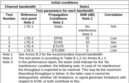
Based on the discussion in clauses 5.5.4.1 to 5.5.4.4 the channel profiles as listed in Table 5.5.4.5-1 for HSPA and Table 5.5.4.5-2 for LTE testing have been selected to challenge the higher layers, but also cover the vast majority of propagation scenarios experienced in field tests. The simulations and measurements as discussed in clause 5.5.4.4 indicate that the VA channel would cover most scenarios experienced in drive tests. The number of test cases should be reasonable as there is no need to repeat all the radio-link tests in TS 34.121-1 [3] ,TS 34.122[4] or TS 36.521-1 [2]. It is more important to cover the missing aspects. The aim has been to find a limited number of relevant propagation conditions (4-6) to achieve a reasonable test count, including the static condition.
Table 5.5.4.5-1: Test Points for HSPA Propagation Condition Geometry Justification Static No interference Note 1
To check that upper-layers do not constrain data throughput
PA3 20dB To exhibits large TBS variations (see clause 5.5.4.3) and very common scenarios for high-data rate requiring processing capability
VA30 10dB Fast variations and VA occurs frequently in deployments VA120 0dB A high BLER scenario may trigger
higher layer retransmissions, and also addresses the high speed scenario in the work item objective
PB3 0dB Most common high-dispersion case Note 1: In the performance report, the tester shall indicate for the ‘No
Interference’ condition, the following note: In case of 'no interference', the throughput is expected to be maximal. This may be the maximum theoretical throughput or below. In the latter case it cannot be distinguished, whether UE limitations, or signal generator limitations with respect to EVM, or both contribute to this.
Table 5.5.4.5-2: Test Points for LTE
Propagation Condition SNR Justification Static No interference Note 1
To check that upper-layers do not constrain data throughput
EPA5 20dB To exhibits large TBS variations (see clause 5.5.4.3) and very common scenarios for high-data rate requiring processing capability
EVA5 10dB EVA occurs frequently in deployments EVA70 20 dB
Adds EVA70, high SNR coverage which is common in low
frequency(<1GHz) band networks
EVA200 20 dB
Covers high doppler, high SNR scenario which is common in high frequency (≥1GHz)band networks ETU70 0dB Fast variations and most common
high-dispersion case
ETU300 0dB A high BLER scenario may trigger higher layer retransmissions, and also addresses the high speed scenario in the work item objective
Note 1: In the performance report, the tester shall indicate for the ‘No Interference’ condition, the following note: In case of 'no interference', the throughput is expected to be maximal. This may be the maximum theoretical throughput or below. In the latter case it cannot be distinguished, whether UE limitations, or signal generator limitations with respect to EVM, or both contribute to this.
5.5.5 Traffic
Profiles
The request from the GCF Steering Group was to measure the average UE Application Layer Data Throughput using simulated realistic radio conditions. In order to support this requirement, it is proposed to consider QCI 9 to keep the UE Application Layer Data Throughput testing in-line with TS 36.508 and the QCI used for all of the 36.521-1 clause 8 test cases including the max sustained data rate test.
5.6
Data Transfer Scenarios
5.6.1 FTP
Transfers
It is proposed to execute the following data transfer scenarios for FTP. - Downlink Only
- Uplink Only
- Bi-Directional (concurrent and alternating based on test purpose)
5.6.2 UDP
Transfers
It is proposed to execute the following data transfer scenarios for UDP. - Downlink Only
- Uplink Only
- Bi-Directional (concurrent)
5.7 Statistical
Analysis
5.7.1
Layer 1 Receiver and Performance Tests
When L1 throughput (payload bits/time) is measured during receiver and performance tests, one has to consider the question: In what range around Tmeasured is the true throughput, Ttrue? The parameters in receiver and performance tests
are better known and allow us to answer this question.
In L1 throughput tests, we have a fixed reference channel so the number of payload bits per block is constant. In a fixed reference channel, we know the maximum throughput.
If the throughput limit is defined as 70% of the maximum throughput, a UE near the limit receives 70% correct blocks of constant TBS (returns an ACK) and 30% corrupted or missed blocks (returns NACK or statDTX). If a process works within an incremental redundancy sequence, the samples are not independent. Nevertheless, the error events (corrupted or missed blocks) are mainly independent.
These facts allow one to derive statistics which tells us the variance of the true throughput around the measured one. These statistics are used to determine the minimum number of samples for a given confidence level for the pass/fail decision.
Another aspect that impacts minimum test time is fading. The minimum test time due to fading is long for slow speed propagation profiles and short for high speed ones. The longer minimum test time of the two aspects (statistical or fading) applies.
For UTRAN, each minimum test time is derived from the speed in the profile. The longest time is 164 seconds for the slow speed fading profiles.
For LTE the minimum test time is simulated for each test case, hence we have a large variety of minimum test times. - Longest: 150 000 minimum number of active samples = 1500 seconds net test time
- Shortest: 1366 minimum number of active samples = 13.66 seconds net test time
Most of the layer 1 receiver and performance tests in UTRAN and LTE are governed by the test time due to fading.
5.7.2
Application Layer Data Throughput
During the application layer data throughput, we can also record ACK, NACK and stat DTX in order to calculate the L1 payload bit throughput, although this is not the main target of the application layer test. We can consider the same
question: In what range around Tmeasured is the true throughput, Ttrue? However, the parameters for this measurement are
not as controlled for us to answer the same question.
In contrast to fixed reference channel, the TBS variation is intended to be high and/or fast to exercise aspects of the UE that may impact application layer data throughput. This means that we have high variability in the range of payload bits per block. Therefore, the definition of a maximum throughput at the physical layer is not meaningful as the target throughput is not easily defined.
While throughput is composed of one ratio, (correct blocks) / (correct blocks + (corrupted or missed blocks)), the throughput can be achieved by different compositions of correctly received TBS's. Of course, L1 throughput is still of a statistical nature but the characteristic of the statistics are unknown to us. Hence it is not possible for us to derive a variance of true throughput around the measured throughput.
In contrast to layer 1 receiver and performance tests above, the measured throughput is the final result and not the pass/fail decision.
For fixed reference channel testing, the UE is compared against a predefined limit. Therefore, statistics can be derived to determine the minimum number of samples for a given confidence level for the pass/fail decision. In UE application layer throughput testing, it is desirable to compare the throughput against a variable throughput target or a reference UE. The confidence level in this context is more complex than for a predefined pass/fail limit. We are not necessarily able to calculate the confidence level.
The application layer data throughput is impacted by the L1 throughput. The L1 throughput is inaccessible for analytical statistics as shown above. It can also be expected that the application layer SDUs are not independent. Quite to the contrary, they are dependent in an unknown way. Hence the application layer throughput is inaccessible for statistics as well. Nevertheless, the application layer data throughput is of a statistical nature.
5.7.3
Minimum Test Time
Application layer throughput is of a statistical nature but the statistics are unknown to us.
Hence, we are not able to give a variance of the measured throughput around the true throughput which results in the following complementary statements.
- We are not able to give a confidence level of the measurement when given a predefined test time - We are not able to calculate a minimum test time for a given confidence level.
Therefore, for HSPA, the recommendation for minimum test time is 164 seconds which is derived from lowest speed fading (crossing of 990 wavelengths when travelling with the speed given in the fading profile). This proved its worth during the past and seems meaningful and applicable for the other higher speeds. For static testing, 60 seconds is recommended.
For LTE, the recommended minimum test time for static testing is also set to 60s.
For fading cases, Annex G.3.5 of TS 36.521-1 [2] contains approximately 50 test times for throughput tests with different demodulation scenarios