INSTALLATION AND LOAD TESTING OF HELICAL PILES IN A SENSITIVE FINE-GRAINED SOIL
by
CHRISTOPHER NATHAN WEECH B.A.Sc., The University of Waterloo, 1996
A THESIS SUBMITTED IN PARTIAL FULFILMENT OF THE REQUIREMENTS FOR THE DEGREE OF
MASTER OF APPLIED SCIENCE in
THE FACULTY OF GRADUATE STUDIES (Department of Civil Engineering)
We accept this thesis as conforming to the required standard
...………..
...………..
THE UNIVERSITY OF BRITISH COLUMBIA April 2002
The purpose of this research was to determine how soil disturbance caused by the installation of helical piles in sensitive fine-grained soils affects the mobilization of axial pile capacity at different times after installation.
Six instrumented, full-scale helical piles were installed in lightly overconsolidated, highly sensitive, marine silt and clay at the Colebrook test site in South Surrey, B.C. Prior to pile installation, a detailed in-situ testing program was carried out using field vane shear tests and seismic piezocone penetration testing which included pore pressure dissipation tests.
The excess pore pressures within the soil surrounding the piles was monitored during and after pile installation by means of piezometers located at various depths and radial distances from the pile shaft, and using piezo-ports which were mounted on the pile shaft. The changes in pore pressure during pile installation were indicators of the soil deformations caused by pile installation. The observed pore pressure dissipation around the piles indicated that primary reconsolidation of the soil was complete after about 7 days.
After allowing a recovery period following installation, which varied between 19 hours, 7 days and 6 weeks, piles with two different helix plate spacings were loaded to failure under axial compressive loads. Strain gauges mounted on the pile shaft were monitored during load testing to determine the distribution of loading throughout the pile at the various load levels up to and including failure. Load-settlement curves were generated for different pile sections at different times after installation. The piezometers and piezo-ports were also monitored during load testing and the distribution of excess pore pressures was used as an indicator of the distribution of soil deformations caused by pile displacement.
The undrained shear strengths mobilized by the different sections of the piles were back-calculated from the measured loads using published formulations. An “index of soil destructuring” is proposed which relates the ratio of the mobilized undrained shear strength to the in-situ vertical effective stress at the start of load testing to the corresponding strength ratios of the soil in its intact state and in a completely destructured state. The index of soil destructuring is proposed as the basis for a proposed capacity prediction method that is based on the undrained strength ratio.
ABSTRACT... ii
TABLE OF CONTENTS... iii
LIST OF TABLES... viii
LIST OF FIGURES ... ix
ACKNOWLEDGEMENTS... xiv
1.0 INTRODUCTION... 1
1.1 CONVENTIONAL PILE TYPES... 1
1.2 INTRODUCTION TO HELICAL PILES... 2
1.3 PURPOSE & OBJECTIVES OF RESEARCH... 4
1.4 SCOPE AND LIMITATIONS OF STUDY... 6
1.5 THESIS ORGANIZATION... 7
2.0 BACKGROUND THEORY... 8
2.1 SOIL RESPONSE TO PILE INSTALLATION... 8
2.1.1 Soil Deformations ... 8
2.1.2 Total Stresses and Shear Stresses ... 9
2.1.3 Excess Pore Pressure... 11
2.2 EFFECTS OF CHANGES IN STRESS STATE AFTER INSTALLATION ON PILE CAPACITY. 14 2.2.1 Changes in Radial Effective Stresses... 14
2.2.2 Increases in Pile Capacity with Time... 15
2.2.3 Undrained Shear Strength ... 15
2.2.4 Natural Development of Soil Micro-Structure ... 16
2.2.5 Destruction of Micro-Structure... 18
2.2.6 Recovery of Undrained Shear Strength During Reconsolidation... 19
2.2.7 Summary and Conclusions ... 21
2.3.3 Torque-Capacity Relations ... 26
2.3.4 Conclusions... 27
2.4 PREDICTING PORE PRESSURE DISSIPATION AROUND PILES AND PIEZOCONES... 28
3.0 TEST SITE DESCRIPTION ... 42
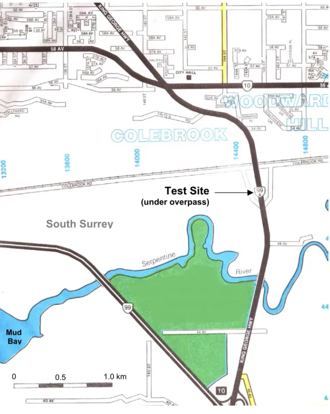
3.1 SITE LOCATION AND GENERAL SURFICIAL GEOLOGY... 42
3.2 CONSTRUCTION OF COLEBROOK ROAD OVERPASS... 42
3.3 SOURCES OF SUBSURFACE INFORMATION... 43
3.3.1 Previous Subsurface Investigations ... 43
3.3.2 Investigation During Present Study ... 44
3.4 SUMMARY OF SUBSURFACE CONDITIONS... 46
3.4.1 Stratigraphy... 46
3.4.2 Index Properties ... 46
3.4.3 Groundwater Conditions and Salt Content ... 47
3.4.4 Field Vane Shear Strengths and Sensitivity... 48
3.4.5 Stress History... 49
3.4.6 Cone Penetration Profiles ... 50
3.4.7 Engineering Parameters from Previous Testing ... 50
4.0 EVALUATION OF SITE-SPECIFIC SOIL PARAMETERS... 59
4.1 UNDRAINED SHEAR STRENGTH... 59
4.2 UNDRAINED STRENGTH RATIO & OVERCONSOLIDATION RATIO... 60
4.3 SHEAR STIFFNESS... 62
4.3.1 Small-Strain Shear Stiffness ... 62
4.3.2 Rigidity Index – G/su... 63
4.4 EXCESS PORE PRESSURE GENERATION DURING CONE PENETRATION... 65
4.4.1 Profiles of Penetration Pore Pressure with Depth... 65
4.4.2 Bq Pore Pressure Parameter ... 66
4.4.3 Vertical Distribution of Penetration Pore Pressure along Cone Probe ... 66
4.5 DISSIPATION TEST RESULTS... 67
4.5.3 Importance of Radial Pore Pressure Distributions on Dissipation... 71
4.5.4 Estimates of Coefficient of Consolidation... 73
4.6 SUMMARY OF ENGINEERING PARAMETERS... 75
5.0 TEST PILES & INSTRUMENTATION ... 91
5.1 DESCRIPTION OF TEST PILES... 91
5.2 INSTRUMENTATION... 93
5.2.1 Amplifier & Data Acquisition System... 93
5.2.2 Piezometers ... 94
5.2.3 Piezo-Ports on Pile Shaft ... 97
5.2.4 Strain Gauge Installations ... 98
5.2.5 Load Cell... 100
6.0 PORE PRESSURE CHANGES DURING AND AFTER PILE INSTALLATION... 107
6.1 PIEZOMETER AND PILE INSTALLATION AND MONITORING PROCEDURES... 107
6.2 PORE PRESSURES GENERATED BY PILE INSTALLATION... 111
6.2.1 Piezometer Measurements During Pile Installation... 111
6.2.1.1 Pore Pressure Changes with Pile Penetration Depth... 111
6.2.1.2 Pore Pressure Changes with Time During Pile Installation... 113
6.2.2 Installation Pore Pressure at Pile Shaft ... 116
6.2.2.1 From Pile Data ... 116
6.2.2.2 Comparison to CPTU Measurements ... 117
6.2.3 Radial Distribution of Pore Pressure... 118
6.2.3.1 From Pile Data ... 118
6.2.3.2 Comparison of Shaft Penetration Pore Pressures with Theoretical Solutions ... 119
6.2.3.3 Estimating Excess Pore Pressures Generated by Helix Plates.... 122
6.2.4 Summary and Conclusions from Pore Pressures Observed During Pile Installation ... 123
6.3 PORE PRESSURE DISSIPATION AROUND PILES... 126
6.3.1 Changes in Radial Distribution... 126
6.3.2 Dissipation at Different Radial Distances... 127
6.3.3 Comparison of Dissipation at Pile Shaft to CPTU Dissipation Curves... 128
6.5 CONCLUSION... 134
7.0 LOAD TESTING ... 151
7.1 TESTING & MONITORING APPARATUS AND PROCEDURES... 151
7.1.1 Test Setup... 152
7.1.2 Test Procedures... 154
7.2 LOAD TEST RESULTS... 155
7.2.1 Load Transferred to Pile During Reconsolidation... 155
7.2.2 Distribution of Load Along Pile During Loading... 157
7.2.3 Load – Settlement Curves... 161
7.2.3.1 Entire Pile... 161
7.2.3.2 Grout Column ... 162
7.2.3.3 Lead Section... 163
7.2.4 Settlement – Time Response... 164
7.2.5 Pore Pressure Response ... 164
7.2.6 Capacity – Time Trends... 167
7.2.7 Bearing Pressure of Helix Plates Compared to CPT Tip Pressure ... 170
7.2.8 Inferred Shear Strengths Mobilized By Piles... 170
7.2.9 Shear Strength – Effective Stress Ratio at End of Dissipation ... 173
7.2.10 Increase in Shear Strength after Complete Pore Pressure Dissipation ... 176
7.3 SUMMARY AND CONCLUSIONS... 178
8.0 ESTIMATION OF SOIL PARAMETERS FOR PREDICTING AXIAL CAPACITY OF HELICAL PILES IN FINE-GRAINED SOILS... 200
8.1 PORE PRESSURE DISSIPATION PERIOD... 201
8.2 UNDRAINED SHEAR STRENGTH AT END OF DISSIPATION PERIOD... 204
8.2.1 Shear Mode Effects on su... 205
8.2.2 Destructured Undrained Strength Ratio... 205
8.2.3 Methods of Determining (su/σ’vo)o Profile... 206
8.2.4 Index of Soil Destructuring... 208
8.3 INCREASE IN SHEAR STRENGTH DUE TO AGING... 209
9.2 NUMERICAL MODELLING... 211
9.3 FIELD TESTING... 212
REFERENCES ...213
APPENDIX A EXCESS PORE PRESSURE FROM THEORY & FIELD OBSERVATIONS
APPENDIX B DISSIPATION SOLUTIONS FOR PILES AND PIEZOCONE PROBES
APPENDIX C SAMPLE BORING LOG (MoTH INVESTIGATION)
APPENDIX D FIELD VANE SHEAR STRENGTH TESTING
APPENDIX E PIEZOCONE PENETRATION TESTING
APPENDIX F PORE PRESSURE GENERATION DURING INSTALLATION OF TEST
PILES
Table No. Table Title Page No.
3.1 Summary of Cone Penetration Tests Carried Out in This Study ... 45
4.1 Summary of Average Engineering Parameters... 76
6.1 Piezometer & Piezo-Port Locations... 108
7.1 Instrumentation for Load Tests... 153
7.2 Load Application Summary... 154
7.3 Summary of Load Proportions Transferred by Different Sections of Test Piles.. 159
7.4 Summary of Mobilized Soil Resistance at Pile Failure ... 168
7.5 Back-Calculated Shear Strengths Mobilized by Piles ... 171
7.6 Undrained Strength Ratio and Index of Soil Destructuring... 175
Figure No. Figure Title Page No.
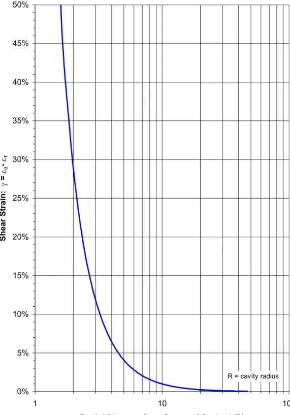
2.1 Radial Distribution of Shear Strain Predicted Around Cylindrical Cavity
Expanded from Zero Initial Radius under Undrained Conditions ... 33
2.2 Comparison Between Idealized Elastic-Plastic Stress-Strain Model and Non-Linear/Strain-Softening Stress-Strain Behaviour ... 34
2.3 Radial Distribution of Shear Stress and Total Principal Stresses from Cylindrical Cavity Expansion Theory ... 35
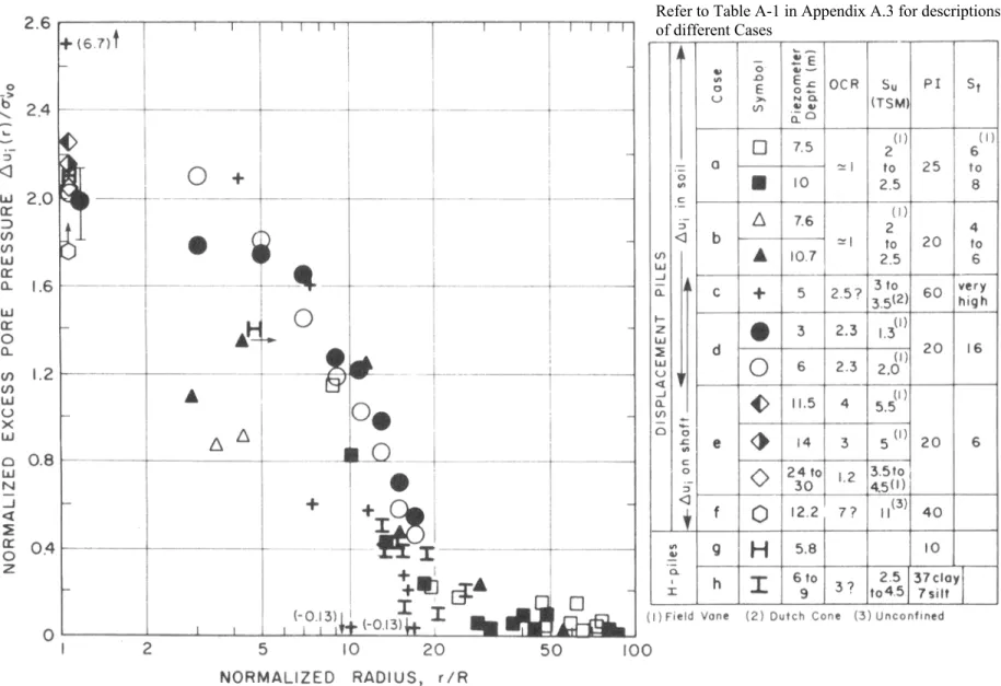
2.4 Measured Excess Pore Pressures at Different Clay Sites due to Installation of Conventional Piles ... 36
2.5 Radial Distribution of Excess Pore Pressure at Different Locations Along Shaft of Cone Probe in Normally Consolidated Boston Blue Clay from SPM Predictions... 37
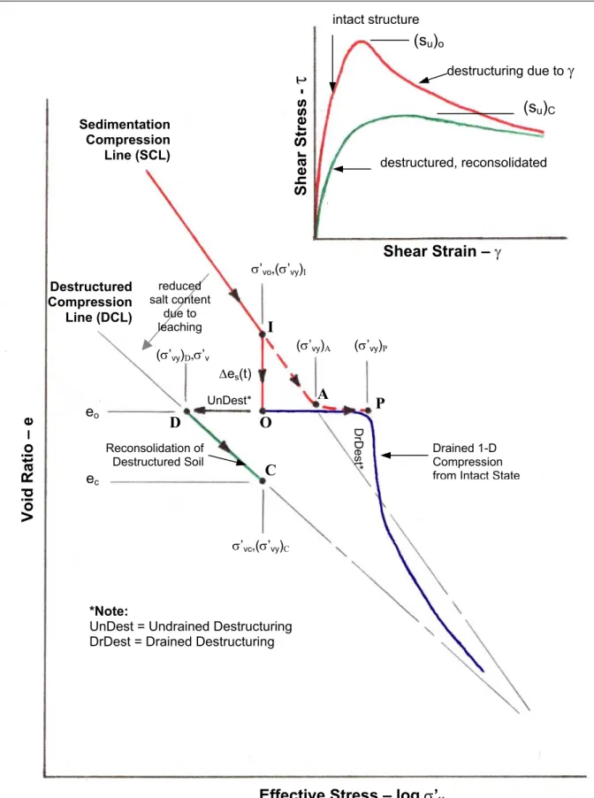
2.6 Development of Micro-Structure and Behaviour of Structured and Destructured Soils in One-Dimensionsal Consolidation and Undrained Shear... 38
2.7 Cylindrical Shear Method... 39
2.8 Model Piles Pulled Out of Very Soft Clay... 39
2.9 Pile Capacity vs. Helix Spacing for Different Soil Strengths... 39
2.10 Assumed Cylindrical Shear Surface for Tapered Helix Groups... 40
2.11 Individual Plate Bearing Method... 40
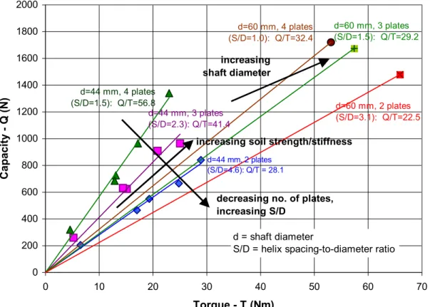
2.12 Capacity vs. Torque for Piles with Different Numbers of Plates and Different Shaft Diameters... 41
2.13 Capacity/Torque Factor vs. No. of Helix Plates ... 41
3.1 Location of Test Site... 52
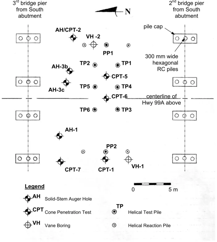
3.2 Test Hole and Test Pile Location Plan... 53
3.3 Soil Stratigraphy at Test Site ... 54
3.7 Example of Cone Penetration Test Results (CPT-7) ... 58
4.1 Variation of Undrained Shear Strength with Depth from CPTU and FVST Data... 77
4.2 Variation of Undrained Strength Ratio with Depth ... 78
4.3 Variation of Overconsolidation Ratio with Depth... 79
4.4 Variation of Small-Strain Shear Modulus and Modulus-Strength Ratio with Depth... 80
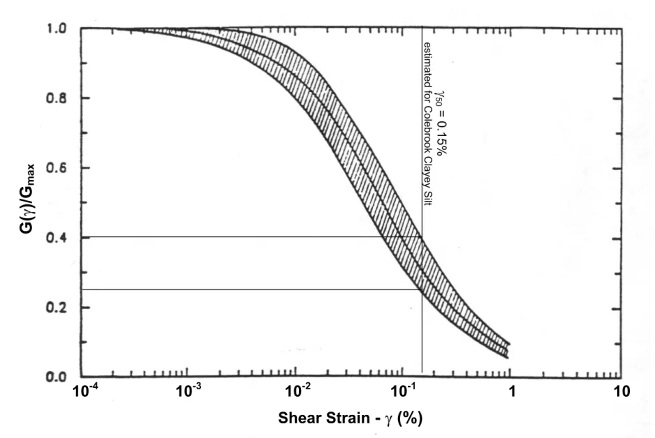
4.5 Typical Shear Modulus Reduction with Strain Level for Plasticity Index between 10% and 20%... 81
4.6 Inferred Variation of Rigidity Index with Depth ... 82
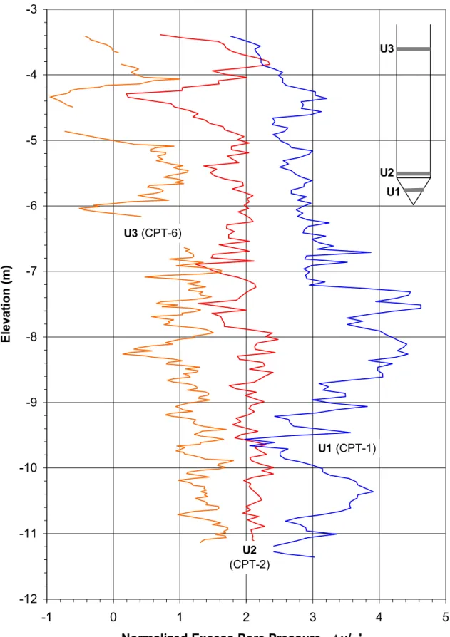
4.7 Representative Profiles of Normalized Excess Pore Pressure During Cone Penetration at Different Locations on Cone Probe ... 83
4.8 Variation of Bq Pore Pressure Parameter with Depth ... 84
4.9 Distribution of Pore Pressure Along Cone Probe during Penetration... 85
4.10 Variation in Excess Pore Pressure with Log Time during Break in Cone Penetration ... 86
4.11 Variation in Excess Pore Pressure with Root Time during Break in Cone Penetration ... 87
4.12 Pore Pressure Redistribution Immediately after Stopping Cone Penetration ... 88
4.13 Comparison of Radial Pore Pressure Distributions after Normalizing by Different “Initial” Shaft Pore Pressures... 89
4.14 Variation in Estimated Coefficient of Horizontal Consolidation with Depth... 90
5.1 Test Pile Geometry ... 101
5.2 Lead Section of Test Piles... 102
5.3 Example of Grout Disc ... 102
5.6 Photograph of Casing... 104
5.7 Photograph of Grout Disc at Bottom of Casing... 104
5.8 Top of Pile After Installation ... 104
5.9 UBC Push-In Piezometer System ... 105
5.10 Piezometer Components ... 105
5.11 Piezo-Port on Pile Shaft ... 106
5.12 Strain Gauge Protection ... 106
6.1 Inclinometer Probe in Guide Casing... 136
6.2 Method of Pile Installation... 135
6.3 Variation of Excess Pore Pressure with Pile Tip Depth a) S/D = 1.5... 136
b) S/D = 3... 137
6.4 Variation of Excess Pore Pressure with Time During Pile Installation... 138
6.5 Excess Pore Pressure at Pile Shaft During Pile Installation ...139
6.6 Installation Pore Pressures at Pile Shaft Compared to CPTU Penetration Pore Pressures...139
6.7 Radial Distribution of Excess Pore Pressure Generated by Penetration of Pile Shaft ... 140
6.8 Radial Distribution of Excess Pore Pressure after Penetration of Helices... 141
6.9 Radial Distribution of Excess Pore Pressure from This Study Compared to Strain Path Method Prediction by Levadoux & Baligh ... 142
6.10 Radial Distribution of Excess Pore Pressure from This Study Compared to Cylindrical Cavity Expansion Prediction ... 142
6.11 Estimate of Excess Pore Pressure Generated by Bottom Helix from CPTU Data... 143
Level of Bottom Helix) during Dissipation Process... 144
6.13 Radial Distribution of Excess Pore Pressure Above & Below Level of Bottom Helix during Dissipation Process... 144
6.14 Average Dissipation Trends for Different Radial Distances from Pile ... 145
6.15 Dissipation Curves from Piezometers/Piezo-Ports Located at Different Radial Distances from Pile... 146
6.16 Dissipation Curves (∆u(t) Normalized by σ’vo) from Piezo-Ports Located on Pile Shaft Compared to CPTU Dissipation Curves ... 147
6.17 Dissipation Curves (∆u(t) Normalized by ∆uo) from Piezo-Ports Located on Pile Shaft Compared to CPTU Dissipation Curves ... 148
6.18 Radial Distribution of Excess Pore Pressure Predicted Around Conventional Pipe Pile Compared to Observed Distribution around Helical Piles ... 149
6.19 Dissipation of Excess Pore Pressure Predicted for Conventional Pipe Pile Compared to Observed Dissipation at Shaft of Helical Piles ... 150
7.1 Load Test Setup at Top of Test Piles ... 183
7.2 Reaction Frame for Load Tests... 183
7.3 Location of Strain Gauges and Piezo-Ports on Test Piles... 184
7.4 Development of Compressive Load in Pile Shaft during Reconsolidation Process ... 184
7.5 Distribution of Load Within Shaft of Test Pile TP6 During Load Test... 185
7.6 Curves of Total Pile Load vs. Pile Settlement ... 186
7.7 Normalized Curves of Total Pile Load vs. Pile Settlement ... 186
7.8 Load – Settlement Curves for Grout Column ... 187
7.9 Load – Settlement Curves for Lead Section (below SG4)... 188
7.10 Load – Settlement Curves for Upper Helices (SG4 – SG6) ... 189
Load Test on Pile TP3 ... 190 7.13 Ratio of Excess Pore Pressure to Induced Vertical Stress below Bottom Helix
during Load Testing... 191 7.14 Pore Pressure Ratio from Pile Load Testing Compared to CPTU Bq Ratio ... 191 7.15 Excess Pore Pressure Generation Around Helical Piles During Load Testing.. 192 7.16 Radial Distributions of Excess Pore Pressures Generated Around Helices at
Point of Pile Failure ... 193 7.17 Changes in Mobilized Resistance with Time for Different Pile Sections ... 194 7.18 Bearing Pressure Induced by Helix Plates at Failure Compared to Profiles of
CPT Tip Resistance ... 195 7.19 Undrained Shear Strengths Mobilized by Different Pile Sections Compared to
Undrained Strengths Measured by In-Situ Tests ... 196 7.20 Changes in Undrained Shear Strength with Time Along Different Pile
Sections... 197 7.21 Undrained Strength Ratios for Different Pile Sections Compared to Undrained
Strength Ratio of Intact Soil Interpreted from In-Situ Tests ... 198 7.22 Changes in Yield Stress due to Aging ... 199
I would like to thank my supervisor, Dr. J.A. Howie, for his valuable suggestions and enthusiasm for this project. I would also like to thank Scott Jackson for his innovative suggestions, design input and problem solving efforts in the development and use of the electronic instrumentation and equipment used in this study, and for his patient explanations of electronic systems and assistance with calibration efforts. Without your help, this project would not have been possible. I would like to extend a special thanks to Ali Amini, who donated a great deal of his valuable time during his own Ph.D. studies to assist with the in-situ testing, pile installation and load testing efforts, and for his thoughtful contributions to many discussions on complex soil behaviour.
The skillful work of Harald Schremp and the other U.B.C Engineering machinists that assisted with the manufacturing of the instrumentation and customizing of the test piles is also greatly appreciated. I would also like to thank Kyle Dolan and Paul Wilson for their efforts with the in-situ testing and soil sampling and the installation and testing of the piles and instrumentation. Their resourceful suggestions and good humour under difficult circumstances are gratefully acknowledged. I am also grateful for the assistance of the other Geotechnical graduate students in helping to collect data: Brian Walker, Meghan Scheffer, and Fiona Esford.
I would like to thank Hubbell Power Systems for their financial support and for manufacturing and delivering the test piles, and Vickars Development Co. for installing the piles and providing the infrastructure and manpower for the test site set-up. Without their assistance, this project would not have been possible. A personal thanks is extended to Bob Vickars who donated a great deal of time and effort to install and load test the piles. ConeTec Investigations Ltd. generously made available personnel and equipment to assist with the in-situ testing.
The financial support of the Natural Sciences and Engineering Research Council of Canada is also gratefully acknowledged.
1.1 CONVENTIONAL PILE TYPES
The following pile types are most commonly used as structural support for foundations1:
• • • • •
timber piles (typically tapered cylindrical geometry), steel pipe piles (installed open-ended or closed-ended), steel H-piles (rolled HP structural sections),
pre-cast reinforced concrete piles (cylindrical, square or octagonal cross-sections), and cast-in-place concrete piles (in pre-bored holes or inside a driven shell or casing).
These piles can be driven into place with a pile hammer, vibrated or jacked into place, or installed in a pre-bored hole. Vibro-installation of piles is typically limited to granular soils. Pre-boring is typically limited to stiff to very stiff fine-grained soils or unsaturated soils in which there is less chance of hole collapse. In soft saturated soils, it is unlikely that a borehole would stay open long enough to be filled with concrete. For this reason, piles installed in soft fine-grained soils are usually driven or jacked into place. This causes an outward displacement of soil away from the pile, the volume of which depends on the pile geometry. Timber piles, pre-cast concrete piles, and steel pipe piles driven closed-ended, are all classified as “displacement” piles, since they cause a large volume of soil displacement. Steel H-piles and open-ended pipe piles are usually classified as “low-displacement” piles. If, however, the bottom of such piles become plugged with soil, they will also cause a large volume of soil displacement.
Piles are typically designed to penetrate through layers of weak and/or compressible soils to reach a relatively competent bearing stratum, in which most of their capacity will be mobilized. This class of piles is typically referred to as “end-bearing piles”.
In some areas, however, the thickness of the weak soil strata may be too extensive to make it practical or economical to advance piles all the way to a competent bearing stratum. In these cases, it is usually preferable to design a raft-type foundation over a pile foundation. However,
raft foundations are not well-suited to some structures; e.g. tall stuctures subjected to significant overturning moments due to lateral loads. Also, the behaviour of the surficial soils (e.g. highly compressible organic silts and peats) can be such that the overall performance of the structure would be improved if the bearing capacity was mobilized within deeper soils, particularly if those soils are significantly less compressible. In these cases, it may be warranted to suspend a group of piles within the relatively weak soils. This class of piles is typically referred to as “friction piles”.
The capacity of friction piles depends almost entirely on the available shear strength of soil that has typically been severely disturbed by the pile installation process. The soil deformations that are induced by the pile installation process alter the total and effective stress states within the soil surrounding the pile and can significantly alter the micro-structure of the soil. Most natural clays are micro-structured and will exhibit some degradation in strength and stiffness when the natural micro-structure is disturbed (Burland, 1990; Leroueil & Vaughan, 1990). The degree of strength and stiffness degradation will vary from soil to soil and will depend on the intensity of the soil deformations caused by pile installation. Further changes in the stress state and soil fabric, and hence the strength and stiffness, can continue to occur with time after pile installation.
Consequently, the strength and the stiffness of the soil around the piles after installation can be significantly different from that which existed prior to pile installation. If reasonably accurate predictions of pile capacity are to be made, it is imperative that the effects of potential changes in the applicable soil parameters be considered, even if it is not yet possible to accurately quantify these changes.
1.2 INTRODUCTION TO HELICAL PILES
Helical piles, also called screw piles, consist of a series of helix-shaped steel plates that are attached to a slender steel shaft. The piles are installed by rotating the shaft using a hydraulic torque unit. As the shaft turns, the helices cut into the soil, and the downward pitch of each helical plate allows the helix plates to pull the rest of the pile into the ground. Extensions are added to the shaft as the helix plates are advanced down to the desired bearing stratum. In order to reach the desired depth:
the torque unit must be able to apply sufficient torque to the pile shaft to overcome the friction along the surface of the shaft and the helix plates, and
•
• the soil must provide enough bearing resistance along the top of the helix plates to overcome the penetration resistance at the tip of the pile shaft.
These piles displace a relatively small volume of soil and can therefore be classified as “low-displacement” piles.
When axial loads are applied to the piles, each of the helix plates transfers compressive stress to the soil above or below the plate (for piles in uplift or compression, respectively) while frictional resistance is mobilized along the pile shaft above the group of helix plates.
The geometry of this type of pile allows soil resistance to be mobilized more or less equally in either compression or in uplift. Hence, this type of design and installation process has been used for decades for tensile soil anchors, or where a foundation is subjected to large overturning moments, such as for masts and towers. Screw piles were reportedly first used in 1838 for the foundations of Maplin Sands lighthouse in the Thames estuary (Narasimha Rao et al., 1991). More recently, large numbers of helical piles were used in the USSR between 1961 and 1964 for the foundations of communication masts up to 254 m high (Narasimha Rao et al., 1991). They were also tested and used in clayey and sandy soils as guy wire anchors for some of the support towers for two 870 km long high-voltage transmission lines extending from the northeastern to southwestern corners of British Columbia (Robinson & Taylor, 1969).
Since the torque units used to install the piles are relatively small, they can be mounted to the boom of a backhoe or other small excavator, or can be hung from a man-portable A-frame. Thus, the installation equipment that is required is limited, and the screw piles and installation equipment can be used in very tight spaces, if necessary, or used in areas with restricted overhead clearance. Also, there are virtually no ground vibrations and relatively little noise created by the installation of helical piles. Consequently, this type of pile is very well-suited and has been used frequently in recent years for foundation repairs, upgrades and retrofits. The lighter installation equipment can also be used in areas with weak and/or compressible subgrades with much less associated disturbance or protection requirements than for conventional pile driving equipment. In any of the above instances, the use of helical piles as pure compression
members can be more practical than conventional driven piles, which must be installed using large pile driving rigs and require a great deal of overhead clearance. Due to the economical use of material and minimal equipment mobilization requirements, this type of pile can provide a more economical alternative to conventional piles in a wide range of applications.
In the past, the design of these piles was typically experience-based, with the assistance of empirical relations between measured installation torque and approximate load-carrying capacity. More recently, a better understanding of the load transfer mechanism acquired from full-scale field testing and laboratory-based model pile research has allowed the development of prediction formulas which are based on soil shear strength parameters. From this research, it was determined that the spacing of the helix plates has a very important effect on the load transfer mechanism, and hence, on the capacity that can be mobilized within a given soil. A summary of the findings of this research will be given in Chapter 2.
When helical piles are used to support compression loads, a problem in the past has been the tendency for the slender shafts to buckle before the full capacity of the helix plates could be mobilized. This was found to be a problem particularly when the helix plates are anchored within a competent bearing stratum that is overlain by soft, weak soils that do not provide adequate lateral support for the slender shaft. To reduce the risk of this occurring, Vickars Developments Co. Ltd. devised and patented a method of “pulling down” a column of grout around the shaft extension sections (the method used to achieve this is described in more detail in Section 5.1). Once the grout cures, the bolted connections between successive pile sections become much more rigid and the composite column can mobilize much greater lateral support from the soil, thereby greatly increasing the buckling resistance of the pile shaft. The larger diameter composite column also provides a greater resistance to lateral pile loads. This adaptation of the more conventional un-grouted helical pile design has been patented by Vickars Development Co. under the trademark PULLDOWN Pile. Pile capacities in excess of 300 kN have been achieved using this type of design.
1.3 PURPOSE & OBJECTIVES OF RESEARCH
There are a number of areas in Canada, North America, and the world, where thick deposits of relatively sensitive fine-grained soils (clayey silts to clays) overlie competent bearing strata. Such deposits are particularly prevalent in coastal regions. In the Fraser River Lowland region
of southwestern British Columbia, there are extensive deposits of fine-grained alluvial sediments that are greater than 30 m thick in places. These clayey silts and silty clays were typically deposited in salt-water environments and have subsequently developed a moderate to high sensitivity due to fresh-water leaching. These soils present significant challenges for construction of civil infrastructure in these areas. To make things even more challenging, the surficial soils in these lowland areas are typically highly organic (peat and organic silts) and highly compressible. Consequently, piled foundations are often used to mobilize adequate load-carrying capacity and/or to reduce foundation settlements to tolerable levels. However, it is not always economically feasible to drive the piles all the way to the dense bearing stratum, or there are economic benefits to installing friction piles within the sensitive silty clays and clayey silts. In these cases, it is very important that the design engineer is aware of the changes in soil properties that occur as a result of disturbance effects during pile installation, and as a result of the subsequent reconsolidation and aging processes. These changes need to be considered carefully when selecting design parameters.
Because of the difficulties in accurately predicting the capacity of piles in such difficult soil conditions, most engineers prefer to use conventional driven piles, with which there has been the most experience, instead of helical piles. This is sometimes the case even when helical piles may be better suited or more economical for a given application. With the recent development of sound theoretical formulations to predict the capacity of helical piles, there is no reason why these piles could not be designed with a similar degree of confidence as for conventional piles. For both types of piles, the accuracy with which the capacity can be predicted will depend to a large degree on the choice of design soil parameters.
The purpose of this research project was:
to obtain a better understanding of the response of sensitive fine-grained soils to the installation of helical piles, and
•
• to investigate the manner and effectiveness with which the different sections of the helical piles mobilize axial resistance within these soils, given the spatial variations in soil properties caused by pile installation and the subsequent changes in these properties with time.
method of estimating the soil strengths mobilized by the different pile sections at different times after installation.
1.4 SCOPE AND LIMITATIONS OF STUDY
To accomplish the research objectives listed above, a detailed field testing program was carried out at a soft soil test site in South Surrey, British Columbia. In this study, a total of 6 instrumented, full-scale helical piles were installed in soft, sensitive, marine silt and clay. The piles were loaded to failure under axial compressive loads, after allowing a recovery period following installation of 19 hours, 7 days or 6 weeks. Piles with two different helix plate spacings were investigated in this study, because of previous research suggesting different load transfer mechanisms for the different spacings. The variations in excess pore pressures within the soil surrounding the piles during and after pile installation were monitored by means of piezometers located at various depths and radial distances from the pile shaft, and using piezo-ports mounted on the pile shaft. The changes in pore pressure during pile installation were indicators of the type and extent of soil deformations caused by pile installation. The dissipation of the excess pore pressures after pile installation was an indicator of the degree of primary consolidation which would have occurred prior to load testing. Strain gauges mounted on the pile shaft were monitored during load testing to determine the distribution of loading throughout the pile at the various load levels up to and including failure. This allowed the changes in the development of resistance along different sections of the piles at different times after installation to be studied in detail. The piezometers and piezo-ports were also monitored during load testing and the distribution of excess pore pressures generated during load testing was used as an indicator of the distribution of soil deformations caused by pile displacement.
A complete understanding of the pile and soil behaviour observed during this study would require a detailed laboratory study of the soil behaviour, which was beyond the scope of the current research project. For this study, site characterization and soil property definition was based on high-quality in-situ testing procedures, complemented by laboratory index testing. The long-term settlement behaviour of helical piles under sustained loads has not been investigated within the scope of this study. The effects of creep can significantly affect the long-term performance of a piled foundation, and so creep can be a critical design issue in some soils and will need to be considered in future research.
1.5 THESIS ORGANIZATION
Chapter 1 of this thesis has laid out the theoretical premise of and practical need for this research project, and has outlined the objectives that were set out for the study. The scope and limitations of the study have also been mentioned.
Chapter 2 provides background theory, based primarily on published information, which is important to, or provides the basis for, the interpretation of the results obtained during this study. A description of the test site is provided in Chapter 3. This includes the location of the test site, the surficial geology in the area, a history of site development and a characterization of the general subsurface conditions at the test site.
The magnitudes and trends with depth of the key engineering parameters that were used in the interpretation of the observed pile behaviour are described in Chapter 4.
A description of the helical test piles and electronic instrumentation used in this study is provided in Chapter 5.
Chapter 6 presents the results of the pore pressure monitoring carried out during pile installation and during the subsequent recovery period before load testing. The implications of the observed pore pressure response are discussed and, wherever possible, the results are compared to similar measurements made with the piezocone penetrometer or to predictions from theoretical solutions.
Chapter 7 presents and discusses the results of axial compressive load tests and the observed trends with recovery time after pile installation. The changes in the observed pile behaviour with time are explained in terms of the degree and distribution of soil disturbance caused by pile installation and the inferred changes in the soil properties caused by installation disturbance, reconsolidation and aging.
In Chapter 8, a rational methodology is proposed for estimating the soil parameters required to predict the axial capacity of helical piles at different times after installation in fine-grained soils. Recommendations for further research are given in Chapter 9.
In this chapter, the results of an extensive literature review are presented with the aim of providing a framework for understanding the soil and pile behaviour observed in this study. This includes:
A conceptual framework for understanding the response of fine-grained soils to pile installation (Section 2.1) and the changes in soil properties that occur during the reconsolidation process following pile installation (Section 2.2).
•
•
•
The existing methods of predicting the capacity of helical piles/anchors installed in fine-grained soils (Section 2.3).
A discussion of the common methods that exist to predict the reconsolidation of the soil with time after pile installation or piezocone penetration, and of the important factors influencing such predictions (Section 2.4).
2.1 SOIL RESPONSE TO PILE INSTALLATION
2.1.1 Soil Deformations
Flaate (1972) makes reference to observations by Skrede (1967) of downward bending of clay layering next to the surface of a driven timber pile. The downward bending of light and dark bentonite layers due to penetration of a flat-ended model pile was observed by Rourk (1961). Flaate also makes reference to observations by Skaven-Haug (1940) of fluid clay that was squeezed up to the ground surface when a pile was driven into quick clay. Similar observations of fluid clay being squeezed out to the ground surface around the shaft of piles driven into Mexico City clay were reported by Zeevaert (1950). Clearly, the process of pile installation causes severe deformation of the soil close to the pile.
The deep penetration of a conventional pile or a cone penetrometer into a saturated soil medium under undrained conditions causes the soil particles to displace in a manner which depends on the geometry of the penetrating body. The deformation of the soil during these displacements causes changes in the strain field around the body until some steady state is achieved, which generally occurs at large distances above the tip of the pile or probe. The distribution of shear
strains caused by undrained penetration of cylindrical objects has been modelled conceptually using Cylindrical Cavity Expansion (CCE) theory and using the Strain Path Method (SPM). Cavity expansion theory is described in Appendix A.1, while the Strain Path Method is described in Appendix A.2.
Cavity expansion theory provides a simple and rational theoretical model for predicting the distribution of shear strain in the soil over the large region deformed by an expanding cavity. The radial distribution of shear strain that is predicted using CCE theory, based on the logarithmic strain formulations described in Appendix A.1.1, is shown on Figure 2.1. The radial distribution of average shear strain around the shaft of a cone penetrometer (which is essentially a miniature pile with a conical tip), which was predicted by Levadoux & Baligh (1980) using the SPM, was almost identical to that predicted by CCE theory.
2.1.2 Total Stresses and Shear Stresses
The soil displacements caused by pile installation are accompanied by increases in the total stresses in all three principal stress directions: radial, cirumferential and vertical. The distribution of these stresses around the pile depends on the strain distribution and on the stress-strain behaviour and pore pressure response of the soil.
Within an annulus of soil surrounding the pile, the shear stresses induced by the soil deformations will have been large enough to cause failure of the soil. The soil that has reached the failure state is said to be “plastic”, and the outer boundary of the region of failed soil is called the “plastic boundary”. The soil beyond this boundary is in a pre-failure state. The location of this boundary relative to the pile depends on the strain distribution around the pile and on the pre-failure stress-strain behaviour of the soil.
The elastic-plastic constitutive model is often used to simply represent the stress-strain behaviour of soils. This model assumes that the stress-strain response up to failure is linear and elastic and the post-failure strength remains constant at the peak strength of the material (i.e. perfectly plastic). However, the pre-failure stress-strain response of natural soils is typically non-linear, since stiffness tends to decrease with increasing strain. Also, during undrained shearing, soils will typically soften or harden once the failure state is reached, depending on the pore pressure behaviour at large strains (either contractive or dilative, respectively). The pore pressure
response is dependent on many factors such as stress history, micro-structure, mode of shear, etc. Soft fine-grained soils tend to be contractive during shearing so that positive pore pressures are generated under undrained conditions. These soils will experience a reduction in shear strength (su) with continued straining after the applied shear stress reaches the peak su. An example of a non-linear, strain-softening (NL-SS) stress-strain curve is compared to that of an elastic-plastic (EL-PL) material on Figure 2.2.
The radial distributions of induced radial, circumferential and vertical total stresses (∆σr, ∆σθ,
∆σz, respectively) and shear stress (τ) around an expanded cylindrical cavity, which were generated from CCE theory (as described in Appendix A.1) using both the NL-SS and EL-PL stress-strain relations from Figure 2.2, are shown on Figure 2.3. The total stresses and shear stress have all been normalized by the undrained shear strength, su. In this particular case, the change in mean total stress (∆σmean) is equivalent to ∆σz. It can be seen that the principal stresses calculated using the EL-PL and NL-SS solutions are very similar across the region where the NL-SS curve is at peak shear stress. However, in the regions where the elastic-plastic and NL-SS stress-strain curves diverge (within the large-strain region and in the pre-failure region), the major and minor principal stress distributions also diverge. At radial distances (r) around the edge of the plastic zone (r = rp), the elastic-plastic model tends to give estimates of ∆σmean that are less than that of the more realistic NL-SS model. At the wall of the cavity (r = R), the elastic-plastic model tends to give estimates of ∆σr that are higher than that of the strain-softening material.
Based on the equation that was used to derive the EL-PL radial stress distribution shown on Figure 2.3 (Equation A15 in Appendix A), the total radial stress at the wall of the cavity will tend to increase with increasing undrained shear strength (su) and with increasing rigidity index (G/su). This is consistent with the observations by Lehane et al. (1994) that the total radial stress measured along the shaft of model piles during installation tends to increase with increasing overconsolidation ratio (OCR).
Figure 2.3 provides a conceptual framework for visualizing the stress distribution around a penetrating pile and for understanding how the distribution of stresses is influenced by the stress-strain response of the soil. However, cavity expansion theory does not necessarily provide an accurate prediction of actual stresses around penetrating cylindrical objects. Jardine et al. (1998)
compared the limit pressures calculated using CCE theory to those measured along the shaft of the Imperial College instrumented model pile. They found that the radial stresses predicted from CCE were 2.5 to 4 times greater than those measured along the shaft of the pile far above the tip in both soft, lightly overconsolidated Bothkennar clay and stiff, highly overconsolidated London clay.
During penetration of a pile or cone penetrometer, the soil is subjected to both vertical and radial displacements, which make the resulting distributions of stresses and strains much more complex than is assumed by cavity expansion theories. The difference between the entirely radial deformation pattern assumed by cavity expansion theories and the actual deformations caused by penetration of piles (eg. as observed by Rourk, 1961) are particularly evident close to the pile surface.
The Strain Path Method (Baligh, 1975; Levadoux & Baligh, 1980; and Baligh & Levadoux, 1980) is expected to provide a more realistic analysis of penetration effects close to the pile surface. The magnitudes of σr, σθ, and σz predicted by Baligh & Levadoux, 1980 (see Figure A-1 in Appendix A) along the surface of the cone probe during penetration are significantly higher close to the face of the cone than they are along the shaft of the probe above the cone. The sharp decrease in σr behind the shoulder of the conical tip, which is predicted by Baligh & Levadoux (1980), is consistent with the trends of σr measured by Jardine et al. (1998) using the Imperial College instrumented model pile. At some distance behind the cone, the stresses reduce to steady state values, which are predicted to be about 33% less than those predicted by CCE theory. Baligh & Levadoux (1980) also predict that σr is the minor principal stress within this region, instead of being the major principal stress, as predicted by CCE theory.
2.1.3 Excess Pore Pressure
The generation of large positive excess pore pressures due to pile driving in normally consolidated to lightly overconsolidated fine-grained soils have been reported in the literature by a number of researchers, including: Bjerrum & Johannessen (1961), Lo & Stermac (1965), Orrje & Broms (1967), Koizumi & Ito (1967), Fellenius & Samson (1976), Bozozuk et al. (1978), Roy et al. (1981), Robertson et al. (1990) and Pestana et al. (2002). Baligh & Levadoux (1980) plotted the measured excess pore pressures from a number of studies at different sites, as shown
on Figure 2.4. Most of the data came from sites with plasticity index between 20 and 25, OCR between 1 and 2.5, and su between 15 and 25 kPa. For these soils, they found that the excess pore pressures at the shaft of the piles was generally on the order of about twice the in-situ vertical effective stress, but decreased with increasing radial distance from the pile, generally becoming negligible at distances of about 20 to 30 pile radii.
The excess pore pressure, ∆u, can be expressed as the sum of two components:
∆u = ∆uoct + ∆ushear (2.1)
where:
∆uoct accompanies a change in mean (or octahedral) total stress (∆σmean or ∆σoct), and •
• ∆ushear accompanies a change in the deviator stresses, and results from the tendency for the soil to change volume during shear.
In saturated soils, ∆uoct = ∆σoct. The magnitude of ∆ushear is strongly dependent on stress history. Normally consolidated clays are strongly contractant when sheared and, therefore, positive
∆ushear are generated during shearing. If structural collapse occurs at failure, as is typically the case in highly sensitive clays, higher positive ∆ushear is generated. Conversely, moderately to heavily over-consolidated clays are strongly dilatant when sheared, so negative ∆ushear are generated. For clays that have been mechanically over-consolidated to an overconsolidation ratio (OCR) of about 2, ∆ushear is typically negligible.
Closed-form solutions exist for the radial distribution of excess pore pressures around cylindrical and spherical cavities (Equations A18a and A18b in Appendix A). However, these solutions are not expected to be very reliable for predicting ∆u close to the surface of a penetrating pile. Also, the elastic-plastic constitutive model that is used to generate the closed-form solutions neglects
∆ushear, as is discussed in Appendix B.2.
Some researchers have suggested accounting for ∆ushear by using pore pressure parameters, such as Skempton’s A or Henkel’s α, determined from laboratory testing, with the shear strength of the soil. Since these parameters are usually determined from the measured pore pressures at
failure, they do not necessarily capture the large-strain ∆ushear response, which is applicable in the region of soil near an expanded cavity or penetrating object.
Some researches have also attempted to predict ∆ushear from effective stress paths inferred from the Cam Clay or Modified Cam Clay (MCC) models, which are based on critical state soil mechanics (eg. Burns & Mayne, 1998, Cao et al., 2001). In both the cited cases, the final effective stress is determined from the undrained shear strength and the slope of the critical state line (M). However, the assumption that the effective stress path reaches the critical state line at the peak undrained shear strength is likely to be incorrect for strain-softening soils, since the critical state only occurs at large strains where the shear strength may have been significantly reduced below its peak value. Cao et al. (2001) acknowledge the difference between the peak and ultimate (large-strain) strengths but state that the MCC model cannot account for large-strain reductions in shear strength.
Levadoux & Baligh (1980) predicted the distribution of ∆u around a penetrating cone probe using the SPM and the total stress soil model MIT-T1 to calculate deviatoric stresses and shear-induced pore pressures. This model was calibrated using observed soil properties from laboratory testing of re-sedimented Boston blue clay (BBC) normally consolidated under Ko conditions. The resulting distribution of ∆u (normalized by the initial vertical effective stress,
σ’vo) around the cone probe is included on Figure A-3 in Appendix A. Radial distributions are reproduced on Figure 2.5 for 3 different locations along the shaft: just above the shoulder of the cone, and at 6R and 10R above the cone tip. Beyond an inner radial boundary (located at rs), ∆u is predicted to decrease approximately linearly with the logarithm of radial distance in a manner that is reasonably consistent regardless of distance behind the shoulder of the cone, rapidly trending toward zero at a relatively consistent outer radial boundary. This is similar to cavity expansion predictions. The reduction in ∆u with distance behind the shoulder of the cone, which occurs close to the surface of the probe, is due to the drop in total stresses behind the shoulder of the cone. This produces a flatter radial gradient of pore pressure within the inner annulus between R and rs. This flat radial gradient, which extends to greater radial distances with greater distance behind the shoulder, explains the slow initial rate of pore pressure dissipation predicted by SPM-based consolidation solutions for locations along the shaft of the penetrometer.
Whittle (1990, 1993) describes a more realistic effective stress soil model, MIT-E3, which avoids having to calculate shear-induced pore pressures separately. This is a more complex model that can account for non-linear pre-failure behaviour, post-peak strain-softening and strength anisotropy in both normally consolidated and over-consolidated soils.
2.2 EFFECTS OF CHANGES IN STRESS STATE AFTER INSTALLATION ON PILE CAPACITY
2.2.1 Changes in Radial Effective Stresses
Measurements of both total radial stresses and pore pressures during and after the installation of pile in fine-grained soils have been reported by Koizumi & Ito (1967), Azzouz & Morrison (1988), Coop & Wroth (1989), Lehane et al. (1994) and Jardine et al. (1998). Such measurements have shown that in normally consolidated to lightly overconsolidated fine-grained soils, the increases in total radial stress that occur during pile installation are accompanied by large positive pore pressures. The net result is that the radial effective stress along the surface of the pile at the end of installation (σ’ri) is reduced below the initial horizontal effective stress in the soil (σ’ho).
After installation, the total radial stress decreases with time in a manner similar to the observed dissipation of excess pore pressure. However, at early times in the dissipation process, the drop in total stress occurs more quickly than the drop in pore pressure (Azzouz & Morrison, 1988; Jardine et al., 1998), such that a further reduction in σ’r is observed. Eventually, the rate of pore pressure dissipation becomes greater than the rate of total stress relaxation, and σ’r increases during the remainder of the dissipation period. The value of σ’r at the end of the dissipation period (σ’rc) tends to be equal to σ’ho for normally consolidated soils but tends to be greater than σ’ho for overconsolidated soils by an amount that increases with increasing OCR of the soil.
Lehane et al. (1994) compiled the results of lateral stress measurements made during penetration of instrumented piles and model piles in clays at a number of test sites. They found that the degree of relaxation of the radial total stress during reconsolidation increased consistently with decreasing OCR and increasing sensitivity. They also found that there were consistent trends of Kc = σ’rc/σ’vo decreasing with decreasing OCR and increasing sensitivity.
2.2.2 Increases in Pile Capacity with Time
Piles that are installed in normally to lightly overconsolidated fine-grained soils typically have low initial capacities. This is attributed to the low effective stresses next to the pile shaft at the end of pile installation, as discussed above. A subsequent increase in capacity with time is typically observed in such soils (eg. Seed & Reese, 1957; Eide et al., 1961; Flaate, 1972; Konrad & Roy, 1987).
Seed & Reese (1957) and Konrad & Roy (1987) have shown that the increase in pile capacity is proportional to the dissipation of excess pore pressure following installation. Konrad & Roy (1987) derived a total radial stress relaxation curve (σr(t) vs t) for a test pile by back-calculating the average radial effective stress acting on the surface of the pile from pile capacities measured at various times after pile installation. The back-calculated σ’r(t) values were added to the pore pressures measured on the pile shaft at the same times to obtain the total radial stresses, σr(t). The resulting σr(t) curve is similar to that measured directly by Azzouz & Morrison (1988) and by Koizumi & Ito (1967). This is strong evidence that the increase in effective stress along the pile shaft during the reconsolidation process controls the increase in soil shear strength and the resulting capacity of friction piles.
2.2.3 Undrained Shear Strength
The preceding discussion indicates that the increase in shear strength along the shaft of a friction pile is controlled by the radial effective stress that occurs during consolidation. It is very difficult to measure lateral soil stress, however, and so the σ’r acting along the pile surface is usually unknown. Consequently, the “total stress” approach to pile design, wherein the frictional resistance along the pile shaft is calculated using the undrained shear strength, su, is still the most common method, since the application of su does not explicitly require a knowledge of the effective stress state of the soil.
However, it is very important to realize that su is not a unique parameter, but depends on the mode of shear relative to the 3-dimensional effective stress state in the soil as well as to the pore pressure response of the soil to shearing. As a result of this anisotropy effect, the su that is measured in different laboratory tests can vary by a factor of 2 or more (for compression vs
extension (TE) and direct simple shear (DSS), the measured magnitudes of su are typically in the following order: (su)TC > (su)DSS > (su)TE.
The su that is measured in in-situ tests may be completely different from all of the above strengths, or may be some average of some or all of the above strengths. Thus, careful consideration must be given to the selection of an appropriate su to use for pile design.
The undrained shear strength measured in fine-grained soils is also known to be strain rate-dependent. In general, su increases logarithmically with increasing strain rate (eg. Kulhawy & Mayne, 1990), although this increase has been found to be greater in soils with higher plasticity (Bjerrum, 1973; Azzouz et al. 1983).
The magnitude of su is directly proportional to the magnitude of the mean effective stress during consolidation. However, since the horizontal effective stresses are not usually known with any confidence in field situations, it is common practice to normalize su by the vertical effective stress (σ’v). The resulting su/σ’v ratio is called the undrained strength ratio. For a given clay that is normally consolidated (NC), (su/σ’v)NC is a constant. For the same clay in an overconsolidated (OC) state, su/σ’v increases according to the overconsolidation ratio (OCR) of the soil, according to the following expression (Ladd et al., 1977):
(su/σ’v)OC = (su/σ’v)NC⋅OCRm (2.2)
Typical values of the exponent, m, range between 0.8 and 1.0.
2.2.4 Natural Development of Soil Micro-Structure
Most natural clayey soils have a distinctive micro-structure which affects the stress-strain behaviour of the soil. This micro-structure is the product of a complex series of geologic processes, which includes:
the depositional environment and post-depositional environment during primary consolidation (salt water or fresh water),
•
• •
secondary consolidation (aging), fresh-water leaching of salt ions,
thixotropic hardening (as described by Mitchell, 1976),
•
• cementation (due to deposition of carbonates, metal oxides, organic matter, etc.), etc.
Soil that has been subjected to aging, thixotropic hardening and/or cementation will have a greater strength and stiffness in its intact state than the same soil that has not been subjected to such processes or has had such effects removed due to a break-down of the micro-structure. The effects of consolidation and aging processes on the development of shear strength were described by Leroueil et al. (1979) and by Leroueil and Vaughan (1990). Since these concepts are critical to the understanding of the behaviour of the test piles in this study, they will be illustrated here using the simplified one-dimensional void ratio – effective stress relations shown on Figure 2.6. Consider a clay deposited in a marine (salt-water) environment. As the soil consolidates under the increasing overburden weight, the vertical effective stress, σ’v, increases and the void ratio, e, decreases along a characteristic line which Burland (1990) has called the “Sedimentation Compression Line” (SCL). This soil is said to be “normally consolidated”, since the consolidation pressure (σ’v) is the largest effective stress that the young soil has been subjected to. While the soil remains normally consolidated, the vertical yield stress, σ’vy (which is commonly referred to as the preconsolidation pressure, or maximum past pressure, and denoted by σ’p), remains equivalent to σ’v, and σ’vy increases along the SCL as the void ratio decreases during primary consolidation. Once the deposition of overburden is complete, and any excess pore pressure has dissipated, the e-σ’v state of the soil will have reached point I on Figure 2.6, at which point the vertical effective stress will be σ’vo, and the vertical yield stress will be (σ’vy)I. Under constant effective stress, fine-grained soils continued to experience a decrease in volume due to secondary consolidation (indicated as ∆es(t) on Figure 2.6). It has been observed that σ’vy continues to increase during this aging period, while the vertical effective stress remains constant at σ’vo. To explain this observed increase in yield stress with time, Bjerrum (1967) proposed a conceptual model in which σ’vy continues to follow the SCL as the void ratio decreases with time. The resulting increase in the yield stress ratio, YSR = σ’vy/σ’vo (which is more commonly referred to as the overconsolidation ratio, denoted by OCR), has the same net effect as if the soil had been preconsolidated to σ’vy and then unloaded. Since the soil has not actually been subjected to any historical unloading, this form of aging-induced overconsolidation is sometimes
referred to as “quasi-preconsolidation”. After sufficient time has passed, the yield stress will reach point A on the SCL on Figure 2.6, and YSRA = (σ’vy)A/σ’vo. Between points I and A, the peak undrained shear strength, su, of the soil tends to increase as σ’vy increases, according to the su/σ’vy ratio of the soil, which remains essentially constant during primary consolidation and aging.
Once the rate of change in void ratio becomes slow enough, thixotropic bonding of the soil particles can occur. This thixotropic hardening causes an additional increase in σ’vy that is independent of void ratio, thereby causing σ’vy to displace to the right of the SCL, which serves to further increase the YSR of the soil. This process is illustrated on Figure 2.6 by the dashed segment between point A and point P. It should be noted that cementation at the particle contacts will have a similar effect on σ’vy as thixotropic hardening. Between points A and P, su continues to increase as σ’vy increases, although the su/σ’vy ratio of the soil may be altered (Leroueil et al. 1979).
Thus, for a natural soil with an in-situ eo and σ’vo (point O on Figure 2.6), the yield stress would be (σ’vy)P and the peak undrained shear strength would be (su)o. A typical stress-strain curve for such a structured soil during undrained shearing is shown in the inset of Figure 2.6. The pre-failure shearing response tends to be relatively stiff and pre-failure tends to be brittle, with a dramatic post-peak drop in strength, due to the shear-induced destruction of the inter-particle bonds and the resulting collapse of the soil structure.
2.2.5 Destruction of Micro-Structure
If a sample of this soil could be recovered and prepared without disrupting the natural micro-structure, and was tested in a one-dimensional consolidation test, the shape of the resulting compression curve would be similar to that shown on Figure 2.6. As the applied vertical effective stress is increased above σ’vo, the micro-structure will remain intact and the soil will behave as an overconsolidated material as long as the yield stress of the soil is not exceeded. Once the applied vertical effective stress reaches (σ’vy)P, any additional strain will cause the inter-particle bonds to be broken and the soil structure to collapse. This breakdown of the natural micro-structure is referred to as “destructuring”. In the drained consolidation test, the structural collapse is accompanied by an abrupt and significant reduction in void ratio, as shown
on Figure 2.6. If the chemistry of the pore water was unchanged since deposition, the drained destructuring would eventually bring the e-σ’v relation back onto the SCL. If, however, the salt content had decreased due to fresh-water leaching, the slope of the compression line may be less than that of the original SCL due to the reduction in salt content, as was observed by Locat & Lefebvre (1982). Thus, the e-logσ’v will drop steeply from σ’vy, pass below the original SCL and approach the “destructured compression line” (DCL) of the soil at the lower salt content. Such e-logσ’v curves are typical of sensitive clays.
If the soil is destructured through undrained shearing, as would occur when a pile is installed in a fine-grained soil, no reduction in void ratio is possible during the destructuring event. Instead, the structural collapse generates large positive pore pressures that cause a reduction in effective stress. Thus, the e-σ’v state of a soil that has been destructured by large undrained shear deformations (typically referred to as remoulding) will tend to move from point O to a point D on the DCL, as shown on Figure 2.6. The yield stress of the soil will also be reduced from (σ’vy)P to some value between (σ’vy)A and (σ’vy)D which depends on the degree of destructuring. A loss of soil memory within soil adjacent to driven piles has been reported by Roy & Lemieux (1986) and Hunt et al. (1998, 2002). If the soil is completely remoulded, the “memory” of the soil will be completely erased and the destructured soil will be normally consolidated (σ’vy = σ’v at point D). The peak undrained shear strength of the soil after primary consolidation is also greatly reduced due to the destruction of the inter-particle bonds and the pore pressures generated by the collapse of the soil structure.
2.2.6 Recovery of Undrained Shear Strength During Reconsolidation
As the effective stress increases due to the dissipation of excess pore pressure and/or increases in total stress, the void ratio decreases along the DCL. Such reductions in void ratio and moisture content have been observed within soil adjacent to driven piles by many researchers: eg. Cummings et al. (1950), Seed & Reese (1957), Flaate (1972), Roy & Lemieux (1986) and Hunt et al. (1998, 2002).
For a completely destructured soil that reconsolidates from point D to point C on Figure 2.6, the void ratio decreases to ec and the vertical yield stress increases to (σ’vy)C = σ’vc. This causes a recovery in the undrained shear strength to (s ) according to the s /σ’ ratio of the destructured
soil. This behaviour has been described by Leroueil et al. (1979) and Leroueil and Vaughan (1990) and evidence of this occurring adjacent to driven piles was given by Rutledge (1950) and Seed & Reese (1957).
From the conceptual example shown on Figure 2.6, (su)C at the end of the pore pressure dissipation period will be significantly less than the intact peak (su)o of the soil prior to pile installation. However, the difference between (su)C and (su)o will depend on the initial YSR of the soil, on the reduction in YSR and effective stress caused by pile installation, on the increase in effective stress during reconsolidation, and on the compression index of the destructured soil. Thus, (su)C could be less than or equal to (su)o. It is unlikely that (su)C would be greater than (su)o under a given mode of shear and at a given strain rate, unless the effective stress in the soil adjacent to the pile is increased above the previous yield stress of the soil, or the soil acquires additional cementation due to chemical or organic processes. The above discussion explains the apparent contradictions between the comparisons of su measured before and after pile installation which are given in the literature: eg. Skempton (1950), Seed & Reese (1957), Orrje & Broms (1967), Flaate (1972), Roy & Lemieux (1986), Hunt et al. (2002).
The typical stress-strain behaviour of the reconsolidated destructured soil during undrained shearing is compared to that of the structured soil (at the same effective confining stress) in the inset of Figure 2.6. The destructured soil typically has a reduced stiffness, strength, and rigidity, and is less brittle (eg. Leroueil et al., 1979; Roy & Lemieux, 1986; Hunt et al., 2002).
The processes of aging and thixotropy/cementation may lead to further increases in the strength and stiffness of the reconsolidated soil with time after the end of the pore pressure dissipation period, as described above. This will depend on many factors, including the response of the pile and soil to loading caused by construction activites.
As a result of all these effects, the value of su that is measured during conventional in-situ and laboratory tests on the soil prior to pile installation is rarely the same as that which is mobilized by a pile at failure. This has frequently been observed to be the case for conventional piles, such that Meyerhof (1976) proposed correcting su by an empirical factor, α, when calculating the side friction on a pile shaft, fs = α⋅su, where α ≤ 1 and generally decreases with increasing overconsolidation.
2.2.7 Summary and Conclusions
The key points from the above discussions are summarized below:
The soil displacements caused by pile installation induce large deformations and shear strains within an annulus of soil surrounding the pile. These deformations cause large positive excess pore pressures to be generated in normally consolidated to lightly overconsolidated saturated fine-grained soils, and can cause a significant break-down of the micro-structure of the soil.
•
•
•
•
Immediately after pile installation, the undrained shear strength of the soil next to the pile has been significantly reduced below the intact strength of the material, and the initial shaft resistance of the pile is typically very low. This is due in part to the high positive pore pressures and reduced effective stresses within the soil next to the pile. The degree of strength loss in the soil will depend on the sensitivity of the soil and on the induced strain levels relative to the threshold strain required to cause structural breakdown. Therefore, the distribution of shear strength around a pile after installation will depend on the distribution of strain caused during installation.
As the excess pore pressures dissipate and the effective stresses increase, the soil next to the pile consolidates to a lower void ratio than in its natural state. The undrained strength increases according to the su/σ’ ratio of the soil in its partly to completely destructured state.
Upon completion of the pore pressure dissipation process, the undrained strength of the soil next to the pile will have reached a value which depends on the magnitude of the principal effective stresses around the pile, and on the su/σ’ ratio of the partly to completely destructured soil. Any degree of structural breakdown will lead to a reduction in the su/σ’ ratio below the su/σ’vo of the intact soil before pile installation. The vertical effective stress after pore pressure equalisation will be equal to σ’vo, while σ’rc will be equal to or greater than σ’ho, depending on the YSR and sensitivity of the soil and the location relative to the pile tip. Thus, the undrained shear strength of the disturbed, reconsolidated soil may be higher than, equal to, or lower than, its natural intact strength, depending on the properties of the soil and location relative to the pile.
The strength may continue to increase with time after completion of dissipation due to aging processes.
•
2.3 CAPACITY PREDICTION METHODS FOR HELICAL PILES/ANCHORS
A literature review suggests that, as early as the 1940s, pioneering work on the bearing capacity of helical piles was being carried out. The testing included model and full-scale load tests, and the results and theories from this testing were published by Wilson (1950). This work included an investigation of the relation between installation torque and bearing capacity.
Using the results of field tests on helical anchors, which were being used as guy-wire anchors for transmission towers within extensive clayey deposits, the pull-out resistance was empirically related to installation torque (Robinson & Taylor, 1969). This relation was was not found to be very consistent, but monitoring during anchor installation was used to determine whether or not a given anchor would need to be proof tested.
More recently, a number of researchers have developed rational analytical methods of calculating helical pile capacity in both compression and uplift based on soil shear strengths. These methods are similar to those developed for under-reamed cast-in-place piles, since the load transfer mechanism of the helix plates on helical piles/anchors is similar to that of under-reams on cast-in-place piles. The behaviour of helical piles in compression and tension has been observed to be very similar (Narasimha Rao, Prasad and Shetty, 1991). Therefore, the analysis methods are essentially interchangeable, provided that the differences in gravitational influences are taken into account
Two distinct methods have been proposed: the “cylindrical shear method” and the “individual plate bearing method”. These methods are described in the following sub-sections, along with the empirical torque-based capacity prediction method. All 3 methods were reviewed by Hoyt & Clemence (1989). They also carried out a statistical analysis of the prediction accuracy of these methods based on the results of 91 helical anchor pull-out load tests carried out on a number of different multi-helix anchor geometries at 24 different sites with sandy, silty and clayey soils. Both the cylindrical shear and individual plate bearing methods require an estimate of the shear strength of the soil to calculate the ultimate resistance mobilized by the helical piles/anchors.
Wherever these methods have been applied to fine-grained soils in the literature, the undrained shear strength, su, of the soil has been used for this purpose.
2.3.1 Cylindrical Shear Method
The cylindrical shear method was proposed by Mooney, Adamczak and Clemence (1985). In this method, a continuous cylindrical failure surface is assumed between the top and bottom helices, as illustrated on Figure 2.7 (the helical pile is shown in uplift; however