White Rose Research Online URL for this paper:
http://eprints.whiterose.ac.uk/160888/
Version: Published Version
Article:
Huang, D., Cui, M., Zhang, G. et al. (2 more authors) (2020) Trajectory optimization and
resource allocation for UAV base stations under in-band backhaul constraint. EURASIP
Journal on Wireless Communications and Networking, 2020 (1). 83. ISSN 1687-1472
https://doi.org/10.1186/s13638-020-01700-w
[email protected] https://eprints.whiterose.ac.uk/
Reuse
This article is distributed under the terms of the Creative Commons Attribution (CC BY) licence. This licence allows you to distribute, remix, tweak, and build upon the work, even commercially, as long as you credit the authors for the original work. More information and the full terms of the licence here:
https://creativecommons.org/licenses/ Takedown
If you consider content in White Rose Research Online to be in breach of UK law, please notify us by
R E S E A R C H
Open Access
Trajectory optimization and resource
allocation for UAV base stations under
in-band backhaul constraint
Dongdong Huang
1, Miao Cui
1, Guangchi Zhang
1*, Xiaoli Chu
2and Fan Lin
3 *Correspondence:1School of Information Engineering, Guangdong University of Technology, Guangzhou, China Full list of author information is available at the end of the article
Abstract
The application of unmanned aerial vehicles (UAVs) to emerging communication systems has attracted a lot of research interests due to the advantages of UAVs, such as high mobility, flexible deployment, and cost-effectiveness. The UAV-carried base stations (UAV-BS) can provide on-demand service to users in temporary or emergency events. However, how to optimize the communication performance of a UAV-BS with a limited-bandwidth wireless backhaul is still a challenge. This paper focuses on
improving the spectrum efficiency of a UAV-BS while guaranteeing user fairness under in-band backhaul constraint. We propose to maximize the minimum user rate among all the users served by the UAV-BS by jointly optimizing the allocation of bandwidth and transmit power, as well as the trajectory of the UAV-BS. As the formulated problem is non-convex, we propose an efficient algorithm to solve it suboptimally based on the alternating optimization and successive convex optimization methods. Computer simulation results show that the proposed algorithm achieves a significantly higher minimum user rate than the benchmark schemes.
Keywords: Unmanned aerial vehicle (UAV), UAV base station, In-band wireless backhaul, Trajectory optimization, Resource allocation
1 Introduction
Unmanned aerial vehicles (UAVs) have the advantages of high mobility, flexible control, easy deployment, and so on and have been used in various fields, such as inspection, cargo delivery, search and rescue, and precise agriculture. Recently, it is found that UAVs can help to improve the communication performance of wireless networks, especially the forthcoming fifth-generation (5G) networks, and this technique is called UAV-assisted wireless communication [1]. Both industrial and academic communities have conducted researches on UAV-assisted wireless communication, which includes performance anal-ysis, resource allocation, UAV placement and trajectory optimization, channel modeling, and information security [2–5]. For example, Facebook has launched its UAV-assisted communication project called Aquila, which uses a fleet of high-altitude UAVs to provide Internet access over a vast area [5].
© The Author(s). 2020Open AccessThis article is licensed under a Creative Commons Attribution 4.0 International License, which permits use, sharing, adaptation, distribution and reproduction in any medium or format, as long as you give appropriate credit to the original author(s) and the source, provide a link to the Creative Commons licence, and indicate if changes were made. The images or other third party material in this article are included in the article’s Creative Commons licence, unless indicated otherwise in a credit line to the material. If material is not included in the article’s Creative Commons licence and your intended use is not permitted by statutory regulation or exceeds the permitted use, you will need to obtain permission directly from the copyright holder. To view a copy of this licence, visithttp://creativecommons.org/licenses/by/4.0/.
UAV-assisted wireless communication has three main types of applications. The first type is called UAV-carried base station (UAV-BS), which uses UAVs as aerial base stations (BSs) to provide on-demand wireless coverage[6–9], especially in temporary or emer-gency events, where terrestrial communication infrastructures fail to work due to damage or overloading [10–17]. The second type is called UAV relaying, which uses UAVs as aerial relays to provide wireless connection for users that cannot communicate to each other directly [18–24]. The third type is called UAV-assisted Internet-of-Things (IoT) network, where UAVs assist the IoT network in collecting/disseminating data from/to its nodes or charging its nodes [25–27].
The researches on UAV-assisted wireless communication can be divided into two directions, namely static UAV wireless communication or mobile UAV wireless com-munication. The researches on the static UAV wireless communication assume that the UAVs in the communication systems are quasi-static and mainly focus on optimizing the placement/deployment of UAVs to improve communication performance. In [13], the placement of a static UAV-BS has been optimized to maximize the revenue and common throughput of the UAV-BS system. Compared to static UAV wireless communication, mobile UAV wireless communication can fully utilize the UAVs’ potential to improve communication performance, by optimizing UAVs’ trajectories [12,15–17, 22–24,28]. The trajectory and transmit power of a UAV-BS have been optimized to achieve secure communication in [12] and [15]. Throughput improvement of UAV-BSs has been investi-gated in [16,17,28], where the trajectories of the UAV-BSs have been designed along with user scheduling and transmit power allocation to maximize the throughput of the sys-tem. An amplify-and-forward (AF) two-hop UAV relaying system has been considered in [22], where the trajectory and transmit power of the UAV relay are optimized to minimize outage probability. Moreover, trajectory optimization algorithms have been proposed to maximize the end-to-end throughput of the multi-hop UAV relaying systems in [23] and [24].
Recently, the issue of backhaul constraint has been taken into consideration in the research of UAV-BSs. Here, the backhaul is defined as the data link connecting the BS and the core network. Unlike the terrestrial wireless networks [29, 30], a UAV-BS does not have a wired backhaul that may restrict its mobility, thus can only use wireless backhaul. In general, there are two types of wireless backhauls, called out-band backhaul and in-band backhaul. The former means that the backhaul is assigned with an extra dedicated spec-trum band outside the specspec-trum of the system’s access link [29,31,32]. Here, the access link is defined as the data link connecting the BS and its serving users. By contrast, the latter lets the backhaul and the access link share the same spectrum band, which has been demonstrated to achieve better higher spectrum efficiency [33–36]. In UAV-BS systems, it is important to guarantee the wireless backhaul’s reliability, which may be a bottleneck of the systems’ communication performance. Several prior works have considered the issue of wireless backhaul in UAV-BSs [29,30,32,33,35–37]. In particular, the problem of maximizing the covering user number of a static UAV-BS with a constant-rate backhaul has been considered in [29]. In [30], the common throughput of a UAV-BS under in-band backhaul is maximized by jointly optimizing the UAV’s placement, bandwidth allocation, and power allocation. A backhaul aware placement scheme for UAV-BSs is proposed in [32], which maximizes the user coverage with a given number of UAV-BSs. In [33], the placement of UAV-BS under in-band backhaul has been studied, where the UAV-BS is
deployed to assist a ground cellular network for improving the network throughput. An algorithm that jointly optimizes the placement of UAV-BS, resource allocation, and user association for multiple UAV-BSs with in-band backhaul has been proposed in [35]. An interference management algorithm is proposed to optimize the user association, trans-mit power allocation, and placement of a UAV-BS with an in-band backhaul [36]. The placement of UAV-BS and user association have been optimized to maximize the users’ sum rate of a static UAV-BS system with in-band backhaul in [37]. The above works show that wireless backhaul has a great impact on the communication performance of UAV-BSs, and careful design is needed to guarantee the reliability of the wireless backhaul and improve performance. As compared to the out-band backhaul, the in-band backhaul can adjust the allocation of spectrum between the backhaul link and the access link to achieve a balance between them according to the dynamics of their channel quality and thus may have a higher spectrum efficiency and is more suitable for the scenario where the spectrum resource is limited [33–36].
In this paper, we investigate trajectory and resource allocation design for mobile UAV-BSs under limited-bandwidth backhaul constraint, which has not been considered by the aforementioned works. To improve the spectrum efficiency of a UAV-BS under in-band backhaul constraint while guarantee user fairness, we propose to maximize the mini-mum rate among all the users served by the UAV-BS by jointly optimizing the allocation of bandwidth and transmit power, as well as the trajectory of the UAV-BS, subject to constraints on the backhaul information causality, mobility of the UAV-BS, total band-width, and maximum transmit power. To the best of our knowledge, this topic has not been addressed by prior works. As the formulated problem is non-convex, we propose an efficient algorithm to solve it suboptimally, by applying the alternating optimization and successive convex optimization (SCO) methods. Specifically, to decouple the opti-mization variables of the formulated problem, we divide them into two sets, where one includes the bandwidth and transmit power variables and the other includes UAV trajec-tory variables. Then, we divide the formulated problem into two subproblems and solve them alternately in an iterative manner, where subproblem 1 optimizes the bandwidth and transmit power with fixed UAV trajectory and subproblem 2 optimizes the UAV tra-jectory with fixed bandwidth and transmit power. We solve subproblem 1 optimally and solve subproblem 2 suboptimally by using the SCO method. The obtained results demon-strate the efficiency and necessity of joint bandwidth, transmit power, and trajectory optimization in maximizing the minimum user rate of a UAV-BS.
The rest of this paper is organized as follows. Section2presents the system model and problem formulation. In Section3, the proposed efficient algorithm to solve the con-sidered problem is presented. In Section 4, computer simulation results are presented to show the performance of the proposed algorithm. Finally, Section5summarizes this paper.
2 System model and problem formulation
2.1 System model
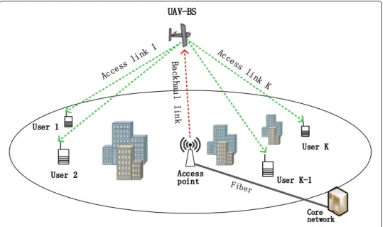
As shown in Fig.1, we consider a UAV-BS that is servingKrandomly distributed users on the ground. The UAV-BS connects to an access point (AP) to receive/send the users’ data from/to the core network. The UAV-BS, the AP, and the users are each equipped with a single antenna. We denote the user set byK{1,. . .,K}and define the communication
Fig. 1A UAV-BS under in-band backhaul constraint
link between the AP and the UAV-BS as backhaul link and that between the UAV-BS and userkas access linkk,∀k∈K. We consider the downlink communication from the UAV-BS to the users, and our work can be extended to the uplink communication scenario straightforwardly.
We express location by using the three dimension (3D) Cartesian coordinate system. The location of userk,∀k ∈ K, is assumed to be fixed at [wT
k, 0]T in meter (m), where
the 2×1 vectorwkdenotes its horizontal coordinate and the superscriptT denotes the
transpose operation. The AP locates at [wT0,H0]T in m with the 2×1 vectorw0
denot-ing its horizontal coordinate andH0being its altitude. For analytical simplicity, the flying
altitude of the UAV-BS is assumed to be fixed atHm [14,31]. Thus, the coordinate of the UAV-BS at timet, 0≤t≤T, can be written as [q(t)T,H]T, where the 2×1 vectorq(t)
denotes its horizontal coordinate at timetandT in seconds (s) denotes its flight dura-tion. To facilitate trajectory optimization for the UAV-BS, we discretize its continuous trajectory{q(t), 0 ≤ t ≤ T}by dividing the flight durationT intoMequal-length time slots and thus obtain a discrete sequence{q[m] ,m=1,. . .,M}, whereq[m] denotes the horizontal coordinate of the UAV-BS at time slotm. Here, the length of each time slot
δtT/Mis sufficiently small such that the distance between the UAV-BS and the AP and
that between the UAV-BS and all users can be regarded as unchanged within each time slot. We assume that the maximum speed of the UAV-BS isVmax in meters per second
(m/s) and that the initial and final locations of the UAV-BS are given, whose horizontal coordinates areq0andqF, respectively. Thus, the mobility constraints on the UAV-BS can
be written as
q[m]−q[m−1] ≤Vmaxδt, m=2,. . .,M (1a)
q[ 1]=q0, q[M]=qF. (1b)
We assume that the altitude of the AP,H0, is sufficiently high, such that there is no
a light-of-sight (LoS) channel. By following the free-space path loss model, the channel power gain of the backhaul link at time slotmcan be written as
β0[m]=γ0d−02[m]=
γ0
(H−H0)2+ q[m]−w02
, (2)
whered0[m] denotes the distance between the AP and the UAV-BS at time slotm, andγ0
is the power gain of a wireless channel with a reference distance of 1 m.
Since the users are on the ground and there may be some obstacles between the UAV-BS and the users, we assume that the access links are quasi-static block fading channels, where the channel gain remains constant within each fading block and may change from one fading block to another. Since the length of each fading block is typically much smaller than that of each time slotδt, for simplicity, we assume that each time slot can be divided
intoL fading blocks, whereL is a sufficiently large integer number. Thus, the channel gain of access linkkat thelth fading block of time slotmcan be modeled ashk[m,l]= √
βk[m]ρk[m,l] [26], whereρk[m,l],∀k,m,l accounts for the small-scale fading effect
and is independently and identically distributed (i.i.d.) and
βk[m]=γ0d−kα[m]=
γ0
(H2+ q[m]−w
k2)α/2
(3) accounts for the large-scale channel fading that depends on the distance between the UAV and userkat time slotm dk[m]. Here,α≥2 denotes the path loss exponent.
We consider the in-band backhaul scenario [33], where the backhaul link and the access links share a common spectrum with bandwidthBin Hertz (Hz). To avoid the co-channel interferences between any two access links and between the backhaul link and the access links, we restrict that the backhaul link and the access links are orthogonal to each other. We denote the bandwidths of the backhaul link and the access linkkat time slotmby
a0[m] andak[m] in Hz, respectively. Thus, the constraints on the bandwidth of all links
can be written as a0[m]+ K k=1 ak[m]≤B, ∀m (4a) a0[m]≥0, ak[m]≥0, ∀m,k. (4b)
We assume that the AP transmits signal to the UAV-BS with a constant powerP0, and
thus, the achievable rate of the backhaul link at time slotmin bits per second (bps) can be expressed as C0[m]=a0[m] log2 1+ β0[m]P0 a0[m]N0 =a0[m] log2 1+ γ0P0 a0[m]N0((H−H0)2+q[m]−w02) , (5)
where N0 denotes the noise power density at the receiver. We assume that the
UAV-BS transmits signal to userkwith power pk[m] at time slotm, which is subject to the following maximum value constraint and non-negative constraint
K
k=1
pk[m]≤pmax, ∀m (6a)
wherepmaxdenotes the maximum transmit power of the UAV-BS. Thus, the achievable
rate of the access linkkat thelth fading block of time slotmin bps can be expressed as
Ck[m,l]=ak[m] log2 1+|hk[m,l]| 2p k[m] ak[m]N0 . (7)
We denote the actual transmission rate from the UAV-BS to userkat time slotmby
Rk[m] and denote the probability operator by Pr(·). Then, the outage probability of access
linkkat thelth fading block of time slotmcan be expressed as
ηk[m,l]=Pr(Ck[m,l]<Rk[m]) =Pr |ρk[m,l]|2< ak[m]N0 2Rk [m] ak[m] −1 βk[m]pk[m] =F a k[m]N02 Rk[m] ak[m] −1 βk[m]pk[m] ηoutk [m] , (8)
whereF(·) denotes the cumulative distribution function of|ρk[m,l]|2. In (8), ηk[m,l]
does not change with the fading block indexldue to the i.i.d. assumption onρk[m,l],
and thus it can be written asηoutk [m]. In order to guarantee the communication reliabil-ity between the UAV-BS and userk, we chooseRk[m] such thatηkout[m,l]= ǫ, whereǫ
denotes the maximum tolerable outage probability. Therefore,Rk[m] can be expressed as
Rk[m]=ak[m] log2 1+F− 1(ǫ)β k[m]pk[m] ak[m]N0 =ak[m] log2 1+ F− 1(ǫ)γ 0pk[m] ak[m]N0(H2+ q[m]−wk2)α/2 , (9)
whereF−1(·)is the inverse function ofF(·).
Since the data received by the users is from the core network, at any time slotm, the sum of actual transmission rates from the UAV-BS to all users should be no greater than the achievable rate of the backhaul link, which is called the backhaul information causality constraint and is given by
K
k=1
Rk[m]≤C0[m] , ∀m. (10)
2.2 Problem formulation
To improve the spectrum efficiency of the UAV-BS system and guarantee a fairness among the users, we consider maximizing the minimum transmission rate of the K
users over the whole flight duration, i.e., mink∈KM1 Mm=1Rk[m], by jointly
optimiz-ing the bandwidths of the backhaul link and all access links over all time slots A
{a0[m] ,ak[m] ,∀m,k}, the power that the UAV-BS uses to transmit signal to each user
over all time slotsP{pk[m] ,∀m,k}, and the trajectory of the UAV-BSQ{q[m] ,∀m},
subject to the mobility constraints of the UAV-BS in (1), the bandwidth constraints in (4), the transmit power constraints in (6), and the backhaul information causality constraint in (10). By introducing an auxiliary variableθ to denote the minimum transmission rate
of all users and omitting the constant term M1, we formulate the considered problem as follows1 (P1) : max A,P,Q,θθ (11a) s.t. (C1) : M m=1 Rk[m]≥θ, ∀k∈K (11b) (C2) :q[m]−q[m−1] ≤Vmaxδt, m=2,. . .,M (11c) (C3) :q[ 1]=q0, q[M]=qF (11d) (C4) :a0[m]+ K k=1 ak[m]≤B, ∀m (11e) (C5) :a0[m]≥0, ak[m]≥0, ∀m,k (11f) (C6) : K k=1 pk[m]≤pmax, ∀m (11g) (C7) :pk[m]≥0, ∀m,k (11h) (C8) : K k=1 Rk[m]≤C0[m] , ∀m. (11i)
Note that the left hand side (LHS) of constraint (C1) and the right hand side (RHS) of constraint (C8) are not jointly concave with respect toA,P, andQ, and the LHS of constraint (C8) is not jointly convex with respect toA,P, andQ. Furthermore, the opti-mization variablesA,P, andQare coupled in (C1) and (C8). Therefore, the formulated optimization problem (P1) is not a convex optimization problem and is difficult to be solved optimally. Nevertheless, in the next section, we will propose an efficient algorithm to solve problem (P1) suboptimally.
3 Proposed algorithm to solve (P1)
First, to decouple the optimization variables of problem (P1), we divide them into two sets, where one set consists of the variables of bandwidth and transmit powerAandP, and the other consists of the variables of UAV trajectoryQ. Then, based on the alternative optimization method, we solve problem (P1) by solving two subproblems alternatively until the objective value of problem (P1) converges, where subproblem 1 optimizes the bandwidthAand transmit powerP, under given UAV trajectoryQ, while subproblem 2 optimizes the UAV trajectoryQunder given bandwidthAand transmit powerP. In the following, we present our proposed method to respectively solve these two subproblems and finally present the overall proposed algorithm.
3.1 Subproblem 1: Joint bandwidth and transmit power optimization given UAV trajectory
Given the UAV trajectoryQ, subproblem 1 optimizes the bandwidth and transmit power allocation of the UAV-BS system, which can be written as
1Adding the UAV-BS altitude as an optimization variable to problem (P1) does not change the structure of it, so the
(P2) : max
A,P,θθ (12a)
s.t. (C1), (C4)−(C8). (12b)
The difficulty of solving problem (P2) lies in the constraint (C8), where the termRk[m]
in the LHS is not jointly convex with respect to the optimization variablesak[m] and
pk[m]. To tackle this difficulty, we introduce auxiliary variablesU {uk[m] ,∀k,m}to
(P2), and consider the following problem: (P3) : max A,P,U,θθ s.t. M m=1 uk[m]≥θ, ∀k∈K (13a) K k=1 uk[m]≤C0[m] , ∀m (13b) uk[m]≤Rk[m] , ∀k∈K, ∀m (13c) (C4)−(C7). (13d)
In problem (P3), the constraints (13a) and (13b) are from the constraints (C1) and (C8), respectively.
Lemma 1There always exists an optimal solution to problem (P3) such that the constraint (13c) is satisfied with equality.
ProofWe assume that ak[m′] and pk[m′], for somem′, are the optimal solution to
problem (P3) such that the constraint (13c) is satisfied with strict inequality. Based on
ak[m′] andpk[m′], we can always find another solution ak[m˜] andpk[m˜], which
sat-isfyak[m˜]≤ ak[m′] andpk[m˜]≤ pk[m′] and satisfy the constraint (13c) with equality,
without decreasing the objective value of (P3). As a result,ak[m˜] andpk[m˜] are another
optimal solution to problem (P3), and the lemma is proved.
When (13c) is satisfied with equality, problems (P2) and (P3) have the same optimal solution onAandP. Thus, we can find the optimal solution of (P2) by solving (P3). Since the RHSs of (13b) and (13c) are jointly concave with respect toAandP, problem (P3) is a convex optimization problem, which can be efficiently and optimally solved by the interior-point method [38].
3.2 Subproblem 2: UAV trajectory optimization given bandwidth and transmit power
Given the bandwidthAand the transmit powerP, subproblem 2 optimizes the trajectory of the UAV-BS, which can be written as
(P4) : max
Q,θ θ (14a)
s.t. (C1)−(C3), (C8). (14b)
Since the LHS of constraint (C8) is not convex with respect toQ, and the LHS of (C1) and the RHS of (C8) are not concave with respect toQ, problem (P4) is not convex and difficult to be solved optimally. In the following, we propose an efficient method to solve it suboptimally.
First, similar to the procedure of solving subproblem 1, we introduce auxiliary variables
S{sk[m] ,∀k,m}to problem (P4) and consider the following problem (P5):
(P5) : max Q,S,θθ (15a) s.t. K k=1 sk[m]≤C0[m] , ∀m (15b) M m=1 sk[m]≥θ, ∀k∈K (15c) sk[m]≤Rk[m] , ∀k∈K, ∀m (15d) (C2), (C3). (15e)
Lemma 2There exist an optimal solution to problem (P5) such that the constraint (15d) is satisfied with equality.
The proof of Lemma 2 is similar to that of Lemma 1 and is omitted here for brevity. According to Lemma 2, problems (P4) and (P5) have the same optimal solution onQ. Thus, we can obtain the solution to (P4) by solving (P5). However, problem (P5) is still difficult to solve since it is not convex due to the fact that the termsC0[m] in (15b) and
Rk[m] in (15d) are not concave with respect toQ.
Next, we develop an efficient method to solve problem (P5) suboptimally, by applying the SCO method. The proposed method find a solution to (P5) in an iterative manner until the objective value of it converges. Without loss of generality, we present how the proposed method works in iterationi+1,i≥0. We denoteQ(i){q(i)[m] ,∀m}as the obtained trajectory solution in iterationi. For simplicity, we denote
D0[m]q[m]−w02, (16a)
D(0i)[m]q(i)[m]−w02, (16b)
Dk[m]q[m]−wk2, (16c)
D(ki)[m]q(i)[m]−wk2. (16d)
By substituting (16a) and (16c) into the expressions ofC0[m] in (5) andRk[m] in (9),
respectively, we observe thatC0[m] andRk[m] are convex with respect toD0[m] and
Dk[m], respectively. Based on the fact that a linear lower bound of a convex function is
its global lower bound, we obtain lower bounds ofC0[m] andRk[m], denoted byClb0[m]
andRlbk[m], respectively, by using their first-order Taylor expansions at the pointsD(0i)[m] andD(ki)[m], respectively, which are shown as follows:
C0[m]≥a0[m] log2 1+ h0[m] (H−H0)2+D(0i)[m] − a0[m]h0[m](log2e) D0[m]−D(0i)[m] ((H−H0)2+D(0i)[m]) (H−H0)2+D0(i)[m]+h0[m] C0lb[m] , (17)
Rk[m]≥ak[m] log2 1+ hk[m] (H2+D(i) k [m])α/2 − ak[m]hk[m](log2e)Dk[m]−D(ki)[m] (H2+D(i) k [m]) (H2+D(i) k [m])α/2+hk[m] Rlbk[m] , (18) whereh0[m]= a0γ0[mP]0N0 andhk[m]= F −1(ǫ)γ0p k[m] ak[m]N0 .
Then, we replaceC0[m] in constraint (15b) andRk[m] in constraint (15d) withC0lb[m]
andRlbk[m], respectively, and recast (P5) as (P6) : max Q,S,θθ (19a) s.t. K k=1 sk[m]≤Clb0[m] , ∀m (19b) M m=1 sk[m]≥θ, ∀k∈K (19c) sk[m]≤Rlbk[m] , ∀k∈K, ∀m (19d) (C2), (C3). (19e)
SinceC0lb[m] andRlbk[m] are concave with respect toq[m], it can be easily observed that problem (P6) is a convex optimization problem, and thus, it can be optimally solved by the interior point method [38].
Remark 1Since C0lb[m]and Rlbk[m]are the lower bounds of C0[m]and Rk[m], the
con-straints(19b)and(19d)in (P6) imply the constraints(15b)and(15d)in (P5), respectively, and thus, the solution obtained by solving (P6) is guaranteed to be a feasible solution to (P5).
Remark 2Since problem (P6) can be optimally solved, the objective value of (P5) with the solution obtained by solving (P6) in iteration i + 1must be no smaller than that with the solution obtained in iteration i. Therefore, the objective value of (P5) is non-decreasing over iterations. Besides, the objective value of (P5) is upper bounded by a finite value, so the obtained solution over iterations is guaranteed to converge to a locally optimal solution of (P5).
3.3 Overall algorithm for solving problem (P1)
The overall algorithm solves subproblems 1 and 2 alternatingly in an iterative manner and is summarized in Algorithm 1, where f(P1)(A,P,Q) denotes the objective value of
problem (P1) with variablesA,P, andQ, andκ >0 andν >0 are thresholds indicating accuracy of convergence. As analysed in the previous two subsections, the objective value of problem (P1) is non-decreasing over iterations, and it is upper bounded by a finite value, so Algorithm 1 is guaranteed to converge to a suboptimal solution of problem (P1). In addition, the complexity of Algorithm 1 isO[Nite(KM)3.5] [38], whereNitedenotes its
Algorithm 1Proposed Algorithm to Solve Problem (P1)
1: Initialization: Set initial values for the optimization variablesA(0), P(0), andQ(0). Calculateη(0)=f(P1)(A(0),P(0),Q(0)). Setl=0.
2: repeat
3: Setl=l+1.
4: Given trajectoryQ(l−1), optimize bandwidth and transmit power by solving prob-lem (P3), and denote the obtained solution byA(l)andP(l).
5: Given bandwidthA(l)and transmit powerP(l), optimize trajectory by the follow-ing iterative process, and the obtained solution will be denoted byQ(l). Set initial variableQˆ(0)=Q(l−1). Calculateξ(0)=f(P1)(A(l),P(l),Qˆ(0)). Seti=0.
6: repeat
7: Seti=i+1.
8: GivenQˆ(i−1), solve problem (P6) and denote the solution byQˆ(i). 9: Calculateξ(i)=f(P1)(A(l),P(l),Qˆ(i)). 10: until ξ(i)−ξξ(i()i−1) < ν. SetQ(l)= ˆQ(i). 11: Calculateη(l)=f(P1)(A(l),P(l),Q(l)). 12: untilη(l)−η(l−1) η(l) < κ. 4 Simulation results
In this section, we present computer simulation results to show the performance of the proposed joint bandwidth, power, and trajectory optimization algorithm, denoted by “B-P-T-OPT" scheme, as compared to the following 4 benchmark schemes.
•Joint bandwidth, power, and trajectory optimization without backhaul link constraint scheme (denoted by “B-P-T-OPT-w/o-BH”): it stands for an ideal case that the UAV-BS network does not have bandwidth constraint on the backhaul link, and it jointly optimizes bandwidth, power, and trajectory. Specifically, the involved optimization problem of “B-P-T-OPT-w/o-BH” does not have the variables{a0[m]}and the constraint (C8) and can
be solved by an alternating optimization method similar to Algorithm 1.
•Joint bandwidth and power optimization with line trajectory scheme (denoted by “B-P-OPT-Line-T”): it lets the UAV-BS fly from its initial location to its final location directly in a line trajectory with constant speedq0−qF/Tand optimizes bandwidth and power
by using the step 4 of Algorithm 1. The line trajectory of this scheme is also used as the initial trajectory in the trajectory optimization of other schemes.
• Trajectory optimization with fixed bandwidth and power scheme (denoted by “T-OPT-Fixed-B-P”): it keeps the bandwidth and power allocation fixed over time, which allocates half of the total bandwidth to the backhaul link and the remaining half uniformly to thekaccess links, i.e.,a0[m]= B2 andak[m]= 2BK,∀m, and allocates transmit power
uniformly over theKusers, i.e.,pk[m]= pmaxK ,∀m. Then, it optimizes the UAV trajectory
by using steps 5–10 of Algorithm 1.
•Joint bandwidth and power optimization with static UAV scheme (denoted by “B-P-OPT-STATIC-UAV”): it fixes the location of the UAV-BS at the top of the AP and optimizes bandwidth and power by using step 4 of Algorithm 1.
In the simulations, we consider a UAV-BS system withK=4 users, which are randomly distributed within a 800×800 m2square region. To demonstrate the differences of dif-ferent schemes, the simulation results are all obtained based on one random realization
of the users’ locations. The AP locates at [ 0, 0, 30]T m, sow0 =[ 0, 0]T m andH0 = 30
m. The flying altitude and the maximum speed of the UAV-BS are set asH =120 m and
Vmax=20 m/s, respectively. The horizontal coordinates of the initial and final locations
of the UAV-BS are set asq0=[−400, 0]T andqF =[ 400, 0]T, respectively. The length of
each time slot is set asδt=0.5 s. The total bandwidth of the system is set asB=10 MHz.
The UAV’s maximum transmit power and the AP’s transmit power are set aspmax=1 W
andP0 = 2 W. The noise power spectral density is set asN0 = −169 dBm/Hz. The
channels between the UAV-BS and the users are assumed be experience Rician fading with Rician factorKc = 10. Thus, the cumulative distribution function of|ρk[m,l]|2is
F(z)=1−Q1(√2Kc,√2(Kc+1)z), whereQ1(x,y)is the Marcum-Q function [26]. The
other parameters are set asγ0= −60 dB,α=2,ǫ =10−2,κ=10−4, andν=10−4.
Figure2 shows the trajectories of the UAV-BS obtained by different schemes in the horizontal plane when its flight duration isT = 50 s, where the trajectories obtained by the “B-P-OPT-Line-T” and “B-P-OPT-STATIC-UAV” schemes are not shown, since the trajectory obtained by the former is just a line connecting the initial location and the final location of the UAV-BS and that of the latter is only a point above the AP. It is observed that by all schemes shown in Fig.2, the UAV-BS tries to get close to the users in some arc trajectory. It is also observed that the trajectory by the benchmark “B-P-T-OPT-w/o-BH” scheme is smoother than that of the other schemes. This is because the benchmark “B-P-T-OPT-w/o-BH” scheme does not have the backhaul bandwidth constraint and does not consider the achievable rate from the AP to the UAV-BS when optimizing trajectory.
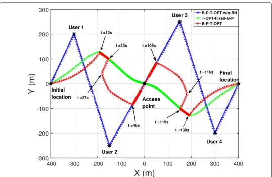
Figure3 shows the trajectories of the UAV-BS obtained by different schemes when
T = 150 s. Compared to Fig.2,T is much greater in Fig.3; thus, there is more degree of freedom for trajectory optimization. In the benchmark “B-P-T-OPT-w/o-BH” scheme, the UAV-BS flies at its maximum speed in straight paths to visit users 1, 2, 3, and 4 suc-cessively and remain static on top of each user for some time, which is the best way to
Fig. 3UAV trajectories obtained by different schemes whenT=150 s
maximize the minimum user rate when there is no backhaul constraint. By contrast, in the proposed “B-P-T-OPT” scheme, the UAV-BS tries to get close to the users, but it does not reach the point above each user. This is because the UAV-BS needs to control its trajectory to ensure that the transmission rate from the UAV-BS to each user does not exceed the achievable rate of the backhaul from the AP to the UAV-BS. Furthermore, in the “B-P-T-OPT” scheme, when the UAV-BS is serving a user, it does not remain static at a certain point, but approaches the user in a line path connecting the user and the AP in low speed. In this way, the UAV-BS can achieve a high data rate from it to the serving user under the backhaul constraint, and it can fly to a good location to get ready to serve the next user. Moreover, it is observed that the trajectory of the benchmark “T-OPT-Fixed-B-P” scheme is obviously different from that of the proposed “B-P-T-OPT” scheme. This is because in the “T-OPT-Fixed-B-P” scheme, the UAV-BS serves all users at the same time within fixed bandwidth, while in the proposed “B-P-T-OPT” scheme, the UAV-BS serves the users one by one, which will be verified in the following.
Figures4,5, and6show the corresponding bandwidth allocation, transmit power allo-cation, and rate results obtained by the proposed “B-P-T-OPT” scheme whenT =150 s. Figure4shows the bandwidths allocated to users 1–4 (access links 1–4) and the backhaul link normalized by the total bandwidthBversus timet. It is observed that the sum of the bandwidths allocated to the users and the backhaul always equals to the total bandwidth. This is because it is optimal to use all spectrum bandwidth to maximize the minimum user rate. It is also observed that at any timet, only one user has been allocated with non-zero bandwidth: in the periods of 0 ≤ t < 37, 37 ≤ t < 75, 75 ≤ t < 112, and 112≤ t≤ 150, users 1, 2, 3, and 4 are allocated with non-zero bandwidth, respectively. That means the UAV-BS serves the users 1 to 4 successively in the proposed “B-P-T-OPT” scheme. Figure5shows the transmit powers of all users versus timet. It is observed that since the UAV-BS serves the users one by one, the UAV-BS allocates all power to the user
Fig. 4Normalized bandwidth of the users and the backhaul optimized by the proposed “B-P-T-OPT” schemes versus timetwhenT=150 s
being served and allocates zero power to the other users. Figure6shows the rates of the users and the backhaul link versus timet. It can be seen that at any timet, the user being served has a positive rate, while the other users all have zero rates. Furthermore, it is observed that the rate of the backhaul link equals to the rate of the user being served at any timet; this is because the proposed “B-P-T-OPT” scheme strikes a balance between the backhaul link and the access links so as to maximize the minimum user rate.
Fig. 5Transmit power of the users optimized by the proposed “B-P-T-OPT” schemes versus timetwhen
Fig. 6Rates of the users and the backhaul link obtained by the proposed “B-P-T-OPT” schemes versus timet
whenT=150 s
Figure7shows the minimum user rate versus the UAV-BS’s flight durationT. For the sake of fairness, Fig.7only compares the schemes under the backhaul constraint. It can be observed that the proposed “B-P-T-OPT” scheme always achieves the highest minimum user rate, and the minimum user rate of it increases with growing T. The “B-P-OPT-Line-T” and “B-P-OPT-STATIC-UAV” schemes that do not optimize UAV trajectory have obvious lower minimum user rates than the proposed scheme, and their minimum user
rates are constant withT. This result shows that by exploiting the mobility of UAV, trajec-tory optimization can significantly improve the minimum user rate performance of the UAV-BS. Furthermore, it is also observed that the “T-OPT-Fixed-B-P” has the lowest rate performance, which shows the necessity of bandwidth and power optimization from the opposite angle. All the above results demonstrate that joint trajectory, bandwidth, and power optimization is effective in improving the minimum user rate performance of the UAV-BS.
5 Conclusion
In this paper, we have considered a UAV-BS under in-band backhaul constraint, where the backhaul link and the access links share the same spectrum. To improve the spectrum efficiency of the UAV-BS and guarantee fairness among users being served, we have inves-tigated maximizing the minimum rate among all users served by the UAV-BS by jointly optimizing the bandwidths of the access links and the backhaul link, the transmit power allocated to all users, and the trajectory of the UAV-BS, and have proposed an efficient algorithm to solve the considered problem. Computer simulation results show that the proposed algorithm achieves a significantly higher minimum user rate than the bench-mark schemes, and demonstrate that jointly optimizing bandwidth, transmit power, and UAV trajectory can more efficiently use all the available resources to provide satisfactory rates for all users.
Abbreviations
UAV: Unmanned aerial vehicle; BS: Base station; UAV-BS: UAV-carried base station; 5G: Fifth-generation; IoT: Internet-of-Things; AF: Amplify-and-forward; SCO: Successive convex optimization; AP: Access point; 3D: Three dimension; LHS: Left hand side; RHS: Right hand side
Authors’ contributions
All authors have reviewed and edited the manuscript and have approved the final manuscript.
Funding
This work was supported in part by the National Natural Science Foundation of China under Grant 61571138, in part by the Science and Technology Plan Project of Guangdong Province under Grant 2017B090909006, Grant 2018A050506015, Grant 2019B010119001, and Grant 2020A050515010, in part by the Special Support Plan for High-Level Talents of Guangdong Province under Grant 2019TQ05X409, and in part by the Science and Technology Plan Project of Guangzhou City under Grant 201904010371.
Availability of data and materials
All input data for this study are included in this published article; the resulting raw output is available from the corresponding author on reasonable request.
Competing interests
The authors declare that they have no competing interests.
Author details
1School of Information Engineering, Guangdong University of Technology, Guangzhou, China.2Department of
Electronic and Electrical Engineering, The University of Sheffield, Sheffield, UK.3Guangzhou GCI Science and Technology
Co., Ltd., Guangzhou, China.
Received: 21 November 2019 Accepted: 4 April 2020
References
1. Y. Zeng, R. Zhang, T. J. Lim, Wireless communications with unmanned aerial vehicles: opportunities and challenges. IEEE Commun. Mag.54(5), 36–42 (2016)
2. Q. Wu, L. Liu, R. Zhang, Fundamental tradeoffs in communication and trajectory design for UAV-enabled wireless network. IEEE Wirel. Commun.26(1), 36–44 (2019)
3. Q. Wu, W. Mei, R. Zhang, Safeguarding wireless networks with uav: a physical layer security perspective. IEEE Wirel. Commun.26(5), 12–18 (2019)
4. X. Lin, V. Yajnanarayana, S. D. Muruganathan, S. Gao, H. Asplund, The sky is not the limit: LTE for unmanned aerial vehicles. IEEE Commun. Mag.56(4), 204–210 (2018)
5. Facebook takes flight. Available: https://www.theverge.com/a/mark-zuckerberg-future-of-facebook/aquila-drone-internet. Accessed 9 Sept 2019
6. H. Zhao, H. Wang, W. Wu, J. Wei, Deployment algorithms for UAV airborne networks toward on-demand coverage. IEEE J. Sel. Areas Commun.36(9), 2015–2031 (2018)
7. C. Lai, C. Chen, L. Wang, On-demand density-aware UAV base station 3D placement for arbitrarily distributed users with guaranteed data rates. IEEE Wirel. Commun. Lett.8(3), 913–916 (2019)
8. N. Sharma, M. Magarini, D. N. K. Jayakody, V. Sharma, J. Li, On-demand ultra-dense cloud drone networks: opportunities, challenges and benefits. IEEE Commun. Mag.8(3), 85–91 (2018)
9. Q. Zhang, M. Mozaffari, W. Saad, M. Bennis, M. Debbah, Machine learning for predictive on-demand deployment of UAVs for wireless communications. IEEE Global Commun. Conf. (GLOBECOM), Abu Dhabi, United Arab Emirates.
56(8), 1–6 (2018)
10. Q. Wu, J. Xu, R. Zhang, Capacity characterization of UAV-enabled two-user broadcast channel. IEEE J. Sel. Areas Commun.36(9), 1955–1971 (2018)
11. M. Mozaffari, W. Saad, M. Bennis, M. Debbah, Unmanned aerial vehicle with underlaid device-to-device communications: performance and tradeoffs. IEEE Trans. Wirel. Commun.15(6), 3949–3963 (2016)
12. G. Zhang, Q. Wu, M. Cui, R. Zhang, Securing UAV communications via joint trajectory and power control. IEEE Trans. Wirel. Commun.18(2), 1376–1389 (2019)
13. J. Lyu, Y. Zeng, R. Zhang, T. J. Lim, Placement optimization of UAV-mounted mobile base stations. IEEE Commun. Lett.21(3), 604–607 (2017)
14. Y. Zeng, X. Xu, R. Zhang, Trajectory design for completion time minimization in UAV-enabled multicasting. IEEE Trans. Wirel. Commun.17(4), 2233–2246 (2018)
15. M. Cui, G. Zhang, Q. Wu, D. W. K. Ng, Robust trajectory and transmit power design for secure UAV communications. IEEE Trans. Veh. Technol.67(9), 9042–9046 (2018)
16. Q. Wu, Y. Zeng, R. Zhang, inGLOBECOM 2017 - 2017 IEEE Global Communications Conference, Joint trajectory and communication design for UAV-enabled multiple access, (2017), pp. 1–6.https://doi.org/10.1109/glocom.2017. 8254949
17. Q. Wu, Y. Zeng, R. Zhang, Joint trajectory and communication design for multi-UAV enabled wireless networks. IEEE Trans. Wirel. Commun.17(3), 2109–2121 (2018)
18. X. Chen, X. Hu, Q. Zhu, W. Zhong, B. Chen, Channel modeling and performance analysis for UAV relay systems. IEEE Trans. Commun.15(12), 89–97 (2018)
19. J. Chen, D. Gesbert, in2017 IEEE International Conference on Communications (ICC), Optimal positioning of flying relays for wireless networks: a LOS map approach, (2017), pp. 1–6.https://doi.org/10.1109/icc.2017.7996921
20. J. Chen, W. Feng, G. Zheng, Optimum placement of UAV as relays. IEEE Commun. Lett.22(2), 248–251 (2018) 21. Y. Chen, N. Zhao, Z. Ding, M. Alouini, Multiple UAVs as relays: multi-hop single link versus multiple dual-hop links.
IEEE Trans. Wirel. Commun.17(9), 6348–6359 (2018)
22. S. Zhang, H. Zhang, K. Bian, Q. He, L. Song, Joint trajectory and power optimization for UAV relay networks. IEEE Commun. Lett.22(1), 161–164 (2018)
23. G. Zhang, H. Yan, M. Cui, Y. Zeng, Y. Liu, Trajectory optimization and power allocation for multi-hop UAV relaying communications. IEEE Access.6(1), 48566–48576 (2018)
24. J. Fan, M. Cui, G. Zhang, Y. Chen, Throughput improvement for multi-hop UAV relaying. IEEE Access.7(1), 147732–147742 (2019)
25. J. Lyu, Y. Zeng, R. Zhang, Cyclical multiple access in UAV-aided communications: a throughput-delay tradeoff. IEEE Wirel. Commun. Lett.5(6), 600–603 (2016)
26. C. Zhan, Y. Zeng, R. Zhang, Energy-efficient data collection in UAV enabled wireless sensor network. IEEE Wirel. Commun. Lett.7(3), 328–331 (2018)
27. J. Xu, Y. Zeng, R. Zhang, UAV-enabled wireless power transfer: trajectory design and energy optimization. IEEE Trans. Wirel. Commun.17(8), 5092–5106 (2018)
28. Q. Wu, R. Zhang, Common throughput maximization in UAV-enabled OFDMA systems with delay consideration. IEEE Trans. Wirel. Commun.66(12), 1–6 (2018)
29. E. Kalantari, M. Z. Shakir, H. Yanikomeroglu, A. Yongacoglu, in2017 IEEE International Conference on Communications Workshops (ICC Workshops), Backhaul-aware robust 3D drone placement in 5G+ wireless networks, (2017), pp. 109–114.https://doi.org/10.1109/iccw.2017.7962642
30. P. Li, J. Xu, in2018 IEEE International Conference on Communication Systems (ICCS), UAV-enabled cellular networks with multi-hop backhauls: placement optimization and wireless resource allocation, (2018), pp. 110–114.https://doi. org/10.1109/iccs.2018.8689218
31. Y. Zeng, R. Zhang, T. J. Lim, Throughput maximization for UAV-enabled mobile relaying systems. IEEE Trans. Commun.64(12), 4983–4996 (2016)
32. W. Shi, J. Li, W. Xu, H. Zhou, N. Zhang, S. Zhang, X. Shen, Multiple drone-cell deployment analyses and optimization in drone assisted radio access networks. IEEE Access.6, 12518–12529 (2018)
33. L. Zhang, Q. Fan, N. Ansari, 3-D drone-base-station placement with in-band full-duplex communications. IEEE Comun. Lett.22(9), 1902–1905 (2018)
34. L. Zhang, N. Ansari, A framework for 5G networks with in-band full duplex enabled drone-mounted base-stations. IEEE Wirel. Commun.26(5), 121–127 (2019)
35. C. Qiu, Z. Wei, Z. Feng, P. Zhang, Joint resource allocation, placement and user association of multiple UAV-mounted base stations with in-band wireless backhaul. IEEE Wirel. Commun. Lett., 1–1 (2019)
36. A. Fouda, A. S. Ibrahim, I. Guvenc, t.M. Ghosh, Interference management in UAV-assisted integrated access and backhaul cellular networks. IEEE Access.7, 104553–104566 (2019)
37. E. Kalantari, I. Bor-Yaliniz, A. Yongacoglu, H. Yanikomeroglu, in2017 IEEE 28th Annual International Symposium on Personal, Indoor, and Mobile Radio Communications (PIMRC), User association and bandwidth allocation for terrestrial and aerialbase stations with backhaul considerations, (2017), pp. 1–6.https://doi.org/10.1109/pimrc.2017.8292783
38. S. Boyd, L. Vandenberghe,Convex Optimization. (Cambridge University, 2004)
Publisher’s Note