Degree Programme in Computer Science and Engineering
Gopika Premsankar
Design and Implementation of a
Dis-tributed Mobility Management Entity
(MME) on OpenStack
Master’s Thesis Espoo, July 15, 2015
Supervisor: Professor Antti Yl¨a-J¨a¨aski Advisor: Sakari Luukkainen D.Sc. (Tech.)
Degree Programme in Computer Science and Engineering MASTER’S THESIS Author: Gopika Premsankar
Title: Design and Implementation of a Distributed Mobility Management Entity (MME) on OpenStack
Date: July 15, 2015 Pages: 77
Major: Data Communication Software Code: T-110 Supervisor: Professor Antti Yl¨a-J¨a¨aski
Advisor: Sakari Luukkainen D.Sc. (Tech.)
Network Functions Virtualisation (NFV) involves the implementation of network functions, for example firewalls and routers, as software applications that can run on general-purpose servers. In present-day networks, each network function is typically implemented on dedicated and proprietary hardware. By utilising virtualisation technologies, NFV enables network functions to be deployed on cloud computing infrastructure in data centers.
This thesis discusses the application of NFV to the Evolved Packet Core (EPC) in Long Term Evolution (LTE) networks; specifically to the Mobility Management Entity (MME), a control plane entity in the EPC. With the convergence of cloud computing and mobile networks, conventional architectures of network elements need to be re-designed in order to fully harness benefits such as scalability and elasticity. To this end, we design and implement a distributed MME with a three-tier architecture common to web applications. We highlight design considerations for moving MME functionality to the cloud and compare our new distributed design to that of a standalone MME. We deploy and test the distributed MME on two separate OpenStack clouds. Our results indicate that the benefits of scalability and resilience can outweigh the marginal increase in latency for EPC procedures. We find that the latency is dependent on the actual placement of MME components within the data center. Also, we believe that extensions to the OpenStack platform are required before it can meet performance and availability requirements for telecommunication applications.
Keywords: Network Functions Virtualisation, Mobility Management En-tity, Evolved Packet Core, OpenStack
Language: English
I would like to thank my supervisor Professor Antti Yl¨a-J¨a¨aski and my in-structor Docent Sakari Luukkainen for giving me the opportunity to work on this topic. I would also like to thank my co-worker Kimmo Ahokas for helping me with the testbed. I am grateful to Dr. Jose Costa-Requena, Vicent Ferrer Guasch and Jes´us Llorente Santos for our discussions on this thesis. I would also like to thank Professor Keijo Heljanko for his insights into distributed design and Professor Mario Di Francesco for our discussions on the presentation of scientific results.
I would like to thank my friends and colleagues for their support. Special thanks to my husband for encouraging me and motivating me to do my best. This thesis would not have been possible without the help and support from my family.
Espoo, July 15, 2015 Gopika Premsankar
This work has been performed in the framework of CELTIC-Plus project C2012/2-5 SIGMONA. The authors would like to acknowledge the contribu-tions of their colleagues, although the views expressed are those of the author and do not necessarily represent the project. This information reflects the consortium’s view, but the consortium is not liable for any use that may be made of any of the information contained therein.
3GPP 3rd Generation Partnership Project APN Access Point Name
BTS Base Transceiver Station DHT Distributed Hash Table
ECGI E-UTRAN Cell Global Identifier ECM EPS Connection Management EMS Element Management System EMM EPS Mobility Management eNodeB Evolved Node B
ESM EPS Session Management EPC Evolved Packet Core EPS Evolved Packet System
E-UTRAN Evolved Universal Terrestrial Access Network GPRS General Packet Radio Service
GRE Generic Routing Encapsulation
GSM Global System for Mobile Communication GTP GPRS Tunneling Protocol
GTP-C GPRS Tunneling Protocol for Control Plane GUMMEI Globally Unique MME Identifier
GUTI Globally Unique Temporary Identifier IE Information Element
IMSI International Mobile Subscriber Identity IMS IP Multimedia Core Network Subsystem IP Internet Protocol
ISDN Integrated Services Digital Network LTE Long Term Evolution
MAC Medium Access Control MME Mobility Management Entity MSISDN Mobile Station ISDN Number NAS Non Access Stratum
OVS Open vSwitch
PDCP Packet Data Convergence Protocol
PDN Packet Data Network or Public Data Network
PGW PDN Gateway
PHY Physical layer
PLMN Public Land Mobile Network QoS Quality of Service
REST Representational State Transfer RLC Radio Link Control
RRC Radio Resource Control S1AP S1 Application Protocol
SCTP Stream Control Transmission Protocol SDN Software-Defined Networking
SGW Serving Gateway
SMS Short Message Service SQL Structured Query Language
SSH Secure Shell
TA Tracking Area
TAI Tracking Area Identity telecom telecommunication UDP User Datagram Protocol
UE User Equipment
UMTS Univeral Mobile Telecommunications System VLAN Virtual Local Area Network
VM Virtual Machine
Abbreviations and Acronyms 7 1 Introduction 11 1.1 Motivation . . . 11 1.2 Research statement . . . 12 1.3 Contribution . . . 13 1.4 Research methodology . . . 13 1.5 Structure of thesis . . . 13 2 Background 15 2.1 Evolved Packet Core (EPC) . . . 15
2.1.1 Architectural elements of EPC . . . 16
2.2 Mobility Management Entity (MME) . . . 18
2.2.1 Interfaces and protocol stacks . . . 19
2.2.2 State information maintained by MME . . . 20
2.3 EPS procedures . . . 21
2.3.1 E-UTRAN initial attach procedure . . . 21
2.3.2 Detach procedure . . . 24
2.4 Network Functions Virtualisation (NFV) . . . 26
2.4.1 Benefits . . . 27
2.4.2 Challenges . . . 28
2.5 Architecture of virtualised EPC network elements . . . 29
2.5.1 1:1 mapping . . . 29
2.5.2 1:N mapping . . . 30
2.5.3 N:1 mapping . . . 32
2.5.4 N:2 mapping . . . 32
2.6 Related work . . . 33
2.6.1 Distributed design for network elements . . . 33
2.6.2 Moving telecommunication systems to the cloud . . . . 34
2.7 Summary . . . 35
3.2 Design of front end (FE) . . . 38
3.2.1 Forwarding S1AP messages . . . 39
3.2.2 Forwarding GTP messages . . . 39
3.2.3 Communicating with the OpenStack load balancer . . . 40
3.2.4 Design considerations . . . 40
3.3 Design of worker . . . 42
3.3.1 Attach procedure . . . 42
3.3.2 Detach procedure . . . 42
3.3.3 Design considerations . . . 43
3.4 Design of state database . . . 44
3.4.1 Redis cluster . . . 45
3.4.2 Redis persistence policies . . . 46
3.4.3 Design considerations . . . 47
3.5 Summary . . . 47
4 Experimental setup and plan 49 4.1 OpenStack . . . 49
4.2 Software components and VMs . . . 50
4.3 Experiments . . . 52
4.4 Summary . . . 53
5 Evaluation 55 5.1 Attach latency compared to original MME . . . 55
5.2 Attach latency depending on placement of FE and worker . . 56
5.3 UE context retrieval time . . . 57
5.4 Effect of Redis persistence policy on attach latency . . . 58
5.5 Demonstration of autonomous scaling on distributed MME . . 59
5.6 Demonstration of resilience . . . 60
5.7 Summary . . . 60
6 Discussion 65 6.1 Evaluation of distributed design for MME . . . 65
6.2 Suitability of OpenStack for telecommunication applications . 67 6.3 Testing framework . . . 67
7 Conclusion 69 7.1 Conclusion . . . 69
7.2 Future work . . . 70
Introduction
Mobile networks today comprise of specialised routers built on proprietary hardware that is designed to meet high performance requirements. Upgrad-ing or expandUpgrad-ing the network demands investment in expensive hardware and the deployment process is slow and cumbersome [60]. Network Functions Vir-tualisation (NFV) has emerged as a solution for mobile network operators to rapidly meet the growing demand for mobile data [11] while simultaneously allowing them to reduce expenditure in specialised hardware. By using vir-tualisation technologies, NFV enables network functions to be deployed on cloud computing infrastructure in data centers. Mobile network operators can then utilise distributed data centers to virtualise and decentralise their networks elastically and cost-effectively [59].
This convergence of mobile networks and cloud computing enables the creation of a flexible, scalable and intelligent core network. A flexible core network is required to meet the requirements of future 5G networks and to integrate new radio access technologies with existing Long Term Evolution (LTE) and WiFi access networks [22, 27]. This thesis focuses on the virtu-alisation of the Evolved Packet Core (EPC) in Long Term Evolution (LTE) networks. We design and implement a distributed Mobility Management Entity (MME), an important control plane element in the EPC network.
1.1
Motivation
The MME is an ideal candidate for virtualisation as it is purely a control plane element and does not handle user data traffic. This means that the MME does not need to make use of specialised hardware for processing data packets and thus its functionality can be moved to general-purpose hard-ware in the cloud. Furthermore, in present-day networks, signalling traffic
is growing rapidly [24, 53, 62]. This can be attributed to continuous keep-alive signalling generated from smartphones [53] and emerging machine to machine applications [24, 62]. An MME deployed on the cloud can employ virtually infinite computing resources to handle this load. However, moving the MME software as a standalone application to the cloud does not allow us to fully leverage the benefits of cloud computing. Our work in re-designing the MME architecture is motivated by the following factors:
• Network functions in the EPC are designed to run on dedicated hard-ware. If the signalling traffic increases substantially, operators need to deploy additional MMEs to handle the increasing load. With an in-telligent architecture, an MME deployed on the cloud can be made to scale autonomously and with minimal network management tasks.
• Network elements in the mobile core are usually overprovisioned to meet peak load demand. However, this can lead to waste of resources during non-peak hours [60]. The MME, being a stateful network ele-ment, cannot be scaled in without affecting existing sessions. A good design for the MME software can enable elasticity through efficient scaling in of virtual resources when no longer required and without affecting end users.
• The failure of a network element impacts the delivery of services to end users. The failure of an MME is particularly significant as it is the main control element in the EPC and is involved in setting up connec-tions for users [63]. Thus, it is important to ensure resilience of the MME and restoration of user sessions in case of failures in the under-lying hardware. Currently, an active-standby redundant architecture with vendor-specific built-in support for transparent failover is used to ensure resilience [31, 51]. State checkpointing and network logging are not suited for cloud deployments as they can contribute to net-work congestion and increased netnet-work latency [31]. Virtualisation of network functions requires resilience to be built into the software ar-chitecture [46]. Thus, it is necessary to build resilience into the MME software.
1.2
Research statement
Section 1.1 identifies the requirements for a virtualised MME in order to harness the benefits of cloud computing. Our goal is to develop a suitable software architecture to achieve a cloud-optimised design for the MME. We
aim to demonstrate the advantages and disadvantages of the chosen archi-tecture through experimental evaluation.
1.3
Contribution
We present a new three-tier architecture for the MME, designed to be flex-ibly scaled out or scaled in depending on user traffic. This new design also achieves resilience to the failure of certain Virtual Machines (VMs) in the cloud. We develop a prototype implementation of the distributed MME and demonstrate the benefits of the new architecture. Additionally, we discuss design choices made for each tier of the architecture and evaluate the effects of these choices. We test and evaluate the performance of the MME on two OpenStack installations.
1.4
Research methodology
We assess the new MME architecture and design choices by experimental evaluation. More specifically the methodology used isexperimental computer science [40], wherein we evaluate our solution through the development of a prototype system. The MME software developed in this thesis is a prototype implementation which supports the basic functionality required to compare its performance to the original design. The developed software is intended as a proof-of-concept to demonstrate the benefits and drawbacks of a novel architecture for the MME.
1.5
Structure of thesis
The rest of the thesis is structured as follows: Chapter 2 introduces the relevant background topics and describes various architecture choices for vir-tualising elements in the EPC. Chapter 3 presents the chosen architecture for the MME and describes our implementation and design considerations. Chapter 4 describes the testbed and experimental plan to evaluate the dis-tributed MME. Chapter 5 presents the results of the experiments. Chapter 6 discusses the results obtained and enhancements to the testbed. Finally, Chapter 7 concludes the thesis.
Background
This chapter provides background information on the technologies and cepts relevant to this thesis. Section 2.1 introduces the EPC and its con-stituent elements. Section 2.2 describes the functions and interfaces of the MME in detail. Section 2.3 discusses two procedures used in the EPC to provide connectivity to end users. Section 2.4 introduces the concept of Net-work Functions Virtualisation (NFV) and its application to EPC. Section 2.5 describes architecture choices for a virtualised element in the mobile core network. Finally, Section 2.6 provides a literature review of current work in the virtualisation of EPC.
2.1
Evolved Packet Core (EPC)
The continuous need for higher data rates, improved Quality of Service (QoS), lower latencies for connection setup, and shorter round trip times has led to a diverse and evolving set of technologies in mobile networks [59]. Figure 2.1 shows the evolution of mobile network architectures from circuit-switched Global System for Mobile Communications (GSM) networks to the current Evolved Packet System (EPS). GPRS networks first introduced packet switching, thereby removing the need for dedicated end-to-end paths. However, these networks could not sufficiently support the high data rates needed for multimedia services. The demand for faster data rates resulted in a new access network in the next generation of Universal Mobile Telecommu-nications System (UMTS) networks. UMTS networks have a core network similar to that in GPRS networks. The need for even faster networks led to the development of a completely new core network and access technol-ogy in the EPS networks. The 3rd Generation Partnership Project (3GPP), a collaboration between seven telecommunication standard development
BTS Node B eNodeB Controller Controller Circuit-switched Packet-switched Core network Access network GSM GPRS UMTS GSM/GPRS UMTS LTE Packet-switched EPC EPS
Figure 2.1: Evolution of mobile network architecture [13]
ganisations1, maintains and develops the standardised specifications related to GSM (including GPRS), UMTS and EPS networks.
The EPS represents the 4th generation (4G) in the evolution of mobile networks. The radio access network of the EPS is known as Long Term Evo-lution (LTE) or Evolved Universal Terrestrial Access Network (E-UTRAN). The Evolved Packet Core (EPC) is the core network of the EPS. The EPC is an all-IP based packet-switched system. Since the EPC no longer contains a circuit-switched domain, all data, voice and Short Message Service (SMS) services are transported over the IP protocol. The EPC has a flat architec-ture with only a few nodes involved in handling user traffic, thereby resulting in fewer protocol conversions, lower latencies and higher performance [14]. Another key feature of the EPC architecture is the separation of control plane (or signalling plane) and data plane (or user plane) elements. Control plane signalling consists of messages related to mobility and management, whereas the data plane carries data packets for user sessions. This separation enables operators to dimension and adapt their networks [14].
2.1.1
Architectural elements of EPC
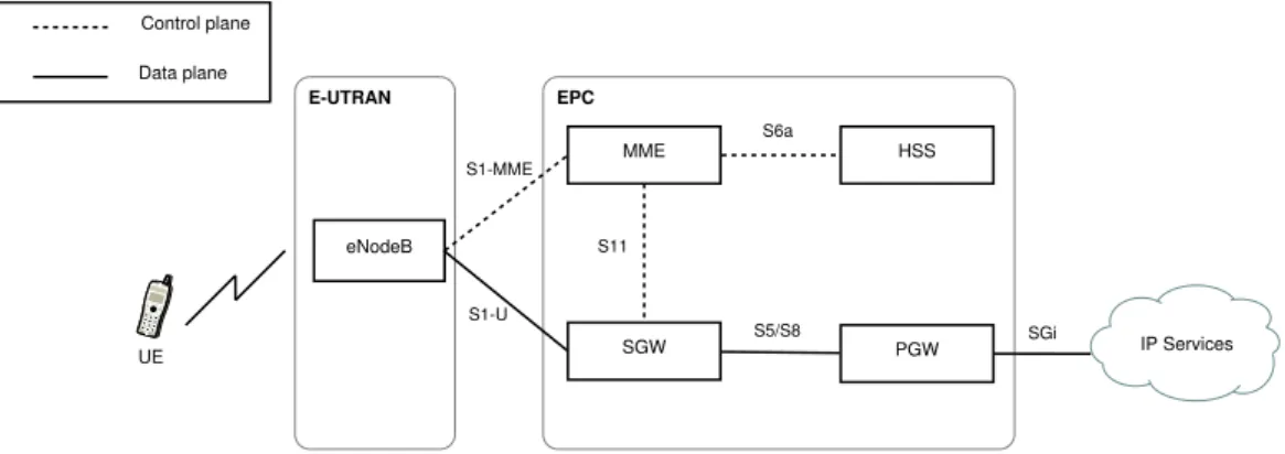
Figure 2.2 shows the basic EPS architecture with the main network elements and interfaces relevant to this thesis. The User Equipment (UE) is the device used by the end user in the network. We use the term UE and user inter-changeably in this thesis. The UE connects to the EPC over the E-UTRAN radio access network. The eNodeB is part of the radio access network and is
eNodeB MME SGW PGW HSS IP Services S1-MME S1-U S11 S6a S5/S8 SGi EPC E-UTRAN Control plane Data plane UE
Figure 2.2: Basic EPS architecture comprised of E-UTRAN radio access network and the core network, EPC
responsible for the air interface towards the UE. The EPC includes the Mo-bility Management Entity (MME), Home Subscriber Server (HSS), Serving Gateway (SGW) and PDN Gateway (PGW). The EPC is connected to exter-nal Packet Data Networks (PDN) which provide IP services to the UE. The EPC could also be connected to the IP Multimedia Core Network Subsystem (IMS) to deliver IP multimedia services (not shown in figure).
A brief description of the elements in EPC is provided below. The MME, being the topic of this thesis, is described in greater detail in Section 2.2.
• HSS – The HSS is the master database for the UEs. It maintains subscription information for each user, including identification param-eters, security information for authentication, ciphering and integrity, user location data, and user profile information [18]. Other network el-ements provide services to the UE by querying the HSS for the required information.
• MME – The MME is a control plane element responsible for man-agement of users. The functions of the MME include authentication, managing user session states, paging, mobility and EPS bearer state management for each UE connected to it.
• SGW– The SGW serves a UE by routing IP data packets to and from the UE [14]. It also acts as the anchor point for UE handovers between eNodeBs and also between non-3GPP networks [18].
• PGW – The PGW is a data plane element that routes incoming and outgoing IP packets from external data networks. Together, the PGW and SGW enable data packets to be transferred between the UE and
external IP networks. The PGW is also responsible for UE IP address allocation, policy enforcement and packet filtering [18].
To provide data services to the UE, EPS networks employ the concept of EPS bearers. An EPS bearer represents a logical connection between the UE and the EPC. It comprises of tunnels between different network elements, over which data packets are actually delivered using IP protocol. IP pack-ets are sent over the radio interface between the UE and eNodeB, tunneled over the S1-U interface between the eNodeB and SGW and transferred over S5/S8 interface between the SGW and PGW. An EPS bearer uniquely iden-tifies traffic flows between a UE and PGW and is associated with a common Quality of Service (QoS) control [17].
2.2
Mobility Management Entity (MME)
The MME is responsible for mobility management of UEs. Right from the moment a user attaches to the LTE network, the MME keeps track of the location of the UE and its state information. It is involved in the initial authentication procedure for a UE and authorises a user to attach to the network. On successful authorisation, the MME manages the establishment of bearers for data connectivity by selecting the appropriate SGW and PGW for a user. It also assigns a temporary identifier to the UE, which is then used in all subsequent procedures to identify the user in the network. When a UE goes into idle mode due to inactivity, the MME is responsible for paging it in case of network-initiated events. It is also the main mobility anchor for a user and handles handovers between eNodeBs as well as to other access networks. The MME terminates the Non Access Stratum (NAS) interface towards the UE and is responsible for ciphering and integrity protection of these NAS messages.
To summarise, among the main functionalities of the MME as listed in [17] are:
• Authentication and authorisation of UEs
• PGW and SGW selection
• Maintaining UE reachability when in idle state
• Bearer management for PDN connectivity
• Mobility management, i.e. management of handovers between eNodeBs or different access networks
• NAS signalling and associated security towards UE
• Lawful interception of signalling traffic
2.2.1
Interfaces and protocol stacks
The interfaces towards the MME, as depicted in Figure 2.2, are described below. In addition to these basic interfaces, the MME has several other interfaces which are not described in this thesis and can be found in [17].
• S1-MME– S1-MME is the control plane interface between the eNodeB and MME. This interface uses S1 Application Protocol (S1AP) [16] over Stream Control Transmission Protocol (SCTP) [57]. SCTP is a reliable, stream-oriented transport protocol, which ensures reliable delivery of messages between the eNodeB and MME. The NAS protocol is used for control plane messaging between the UE and MME. NAS messages are delivered in S1AP messages and are transparent to the eNodeB. The functionality performed by the NAS protocol can be broadly classified into EPS Mobility Management (EMM) for mobility of the UE and EPS Session Management (ESM) for the UE’s IP connectivity [19]. Figure 2.3 shows the protocol stack for communication between the UE, eNodeB and MME. We do not discuss the radio interface protocol stack for the LTE-Uu interface, details of which can be found in [20].
S1AP SCTP IP L2 L1 RRC PDCP RLC MAC PHY S1AP SCTP IP L2 L1 NAS RRC PDCP RLC MAC PHY NAS UE eNodeB MME S1-MME LTE-Uu
Figure 2.3: Control plane protocol stack between UE, eNodeB and MME
• S11 – The MME and SGW exchange control plane messages over the S11 interface. This interface uses GPRS Tunneling Protocol for the control plane (GTP-C) [15] over User Datagram Protocol (UDP) [54], as depicted in Figure 2.4. A GTP tunnel is established per UE over the
S11 interface, which is used to exchange all control plane messages for the particular user [15]. The MME and SGW each maintains a Tunnel Endpoint ID (TEID), an IP address and UDP port number to identify the GTP-C tunnel. IP L2 L1 IP L2 L1 GTP-C GTP-C UDP UDP MME SGW S11
Figure 2.4: Control plane protocol stack between MME and SGW (S11 in-terface)
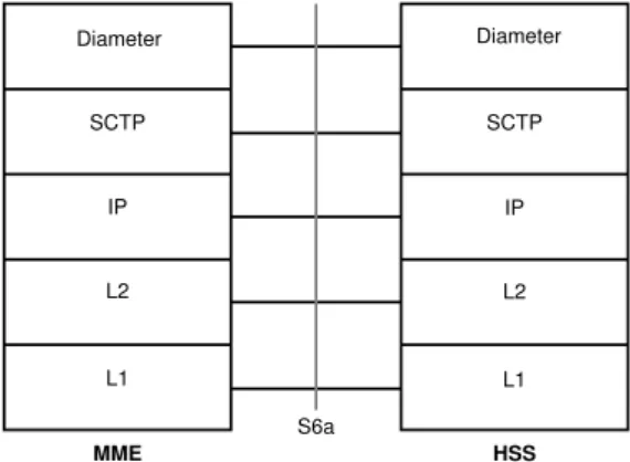
• S6a– The MME and HSS exchange information over the S6a interface. This interface uses Diameter protocol [32] over SCTP. The protocol stack is depicted in Figure 2.5.
IP L2 L1 IP L2 L1 MME HSS Diameter Diameter SCTP SCTP S6a
Figure 2.5: Control plane protocol stack between MME and HSS (S6a inter-face)
2.2.2
State information maintained by MME
An MME maintains information on a UE based on its state in the network. For each UE attached to it, the MME maintains a mobility management
context and information about EPS bearers established. A subset of the information stored on an MME is provided in Table 2.1. Only those fields relevant to this thesis have been included in this table. A complete list of all fields stored on an MME is provided in [19]. The state information main-tained on an MME is often referred to as the UE context. This information varies depending on the state of the UE in the network. For example, when a UE detaches from the network, a small subset of its information is still stored, such as user identifiers and security context information. However, the location of the UE is no longer stored. When a UE is connected to the network and an EPS bearer exists, the MME associated with the UE knows the location of the UE to the tracking area (TA) where it is registered from.
2.3
EPS procedures
This section describes two procedures – initial attach and detach procedures, used in EPS networks to provide connectivity to end users. We implement only these procedures on the MME.
2.3.1
E-UTRAN initial attach procedure
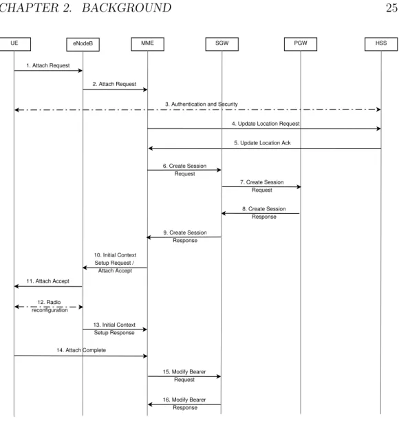
The attach procedure allows a UE to register to the network and enables IP connectivity by creating a default EPS bearer [17] for the UE. Figure 2.6 shows the call flow for an initial attach to the LTE network. A brief description of the initial attach procedure, including the main messages and their important Information Elements (IEs), is provided below:
1. The UE attempts to attach to the network by sending an Attach Request, which includes the UE’s International Mobile Subscriber Identity (IMSI), attach type and ESM container for requesting data connectivity.
2. On receiving this message, the eNodeB assigns an identifier to the UE, known as the eNodeB UE S1AP ID. The eNodeB then selects an ap-propriate MME and forwards the Attach Request to it. The message is sent as part of an S1AP message, encapsulated in a NAS message along with information on the current location of the UE.
3. As part of the authentication and security step, the MME requests for authentication vectors from the HSS using anAuthentication Infor-mation Request. The HSS responds with the requested information
Field Description
IMSI IMSI is the subscriber’s permanent identity MSISDN Basic MSISDN of the UE; depending on whether
present in HSS
MM State MM state of the UE: ECM-IDLE, ECM-CONNECTED or EMM-DEREGISTERED GUTI Globally Unique Temporary Identity assigned to
the UE
MME IP address for S11 MME IP address for S11 interface used by SGW MME TEID for S11 MME Tunnel Endpoint Identifier for S11 interface SGW IP address for S11 SGW IP address for S11 interface
SGW TEID for S11 SGW Tunnel Endpoint Identifier for S11 interface eNodeB address in use
for S1-MME
IP address of the eNodeB currently used for S1-MME interface
eNodeB UE S1AP ID Unique identity for the UE within eNodeB MME UE S1AP ID Unique identity for the UE within MME
TAI of last TAU Tracking Area Identity of the TA in which the last Tracking Area Update was initiated
E-UTRAN CSG ID Last known E-UTRAN Cell Global Identity NAS security context Key parameters for establishing the NAS security
context including security keys For each active PDN connection
PDN type IPv4, IPv6 or IPv4v6
IP address(es) Allocated IPv4 or IPv6 address
APN in use Access Point Name (APN) currently used PGW address (control
plane)
IP address of PGW used for sending control plane signalling
PGW TEID for S5/S8 (control plane)
PGW TEID for S5/S8 interface for control plane APN-AMBR Maximum Aggregated uplink and downlink MBR
values EPS subscribed QoS
pro-file
Bearer level QoS parameters for the default bearer For each bearer within the PDN connection
EPS Bearer ID Unique identifier for the EPS bearer
SGW IP address for S1-U IP address of the SGW for S1-U interface towards eNodeB (data plane)
SGW TEID for S1-U Tunnel Endpoint Identifier of the SGW for the S1-U interface towards eNodeB (data plane)
EPS bearer QoS QoS parameters for EPS bearer Table 2.1: UE Context information stored on MME [19]
in an Authentication Information Answermessage. Once the au-thentication vectors have been acquired, the MME and UE mutually authenticate each other through Authentication Requestand Au-thentication Response messages. On completion of authentication, the MME establishes a NAS security association towards the UE to en-able ciphering and integrity protection of further NAS messages. The MME assigns an MME UE S1AP ID to the UE to uniquely identify it within the MME. A combination of eNodeB UE S1AP ID and MME UE S1AP ID can be used to identify the S1-MME connection for a UE. 4. The MME now sends an Update Location Request message to the HSS to inform the HSS of the user’s registration to the network and to request subscription information for the UE.
5. The HSS acknowledges the request by sending an Update Location Ack which includes the subscription data for the user, such as sub-scribed PDN type, QoS profile and Access Point Name (APN). Based on this information, the MME validates the UE’s presence in the Track-ing Area (TA) and services requested by the UE. If all the checks are successful, a new context is created for the user on the MME.
6. The MME then selects an SGW and allocates an EPS bearer Identity for the default EPS bearer to be created. It sends a Create Session Request towards the SGW to request the creation of a default EPS bearer. This includes the IMSI, EPS bearer ID, IP address of the PGW (which is selected based on subscription data), APN and subscribed QoS values.
7. The SGW sends a Create Session Request to the PGW over the S5 interface, along with other required parameters.
8. On receipt of this message, the PGW creates a new entry in its EPS bearer context table and allocates an IP address to the UE. The PGW can now route packets between the SGW and external data network. The PGW also enforces policy control and generates a Charging ID for the bearer to enable charging of the subscriber. The PGW now sends a Create Session Response to the SGW, which includes the QoS profile and TEID for establishing the S5 tunnel between the SGW and PGW.
9. The SGW then allocates a TEID for the S1-U interface for data trans-fer. It includes this information in the Create Session Response and sends it to the MME.
10. The MME sends an Attach Accept message to the eNodeB in an S1APInitial Context Setup Request message. The Attach Accept includes a Globally Unique Temporary Identifier (GUTI) allocated by the MME for the UE. The Initial Context Setup Request contains pa-rameters to enable the eNodeB to set up the S1-U bearer to the SGW and allocate radio resources to the UE.
11. The eNodeB forwards the Attach Accept to the UE. This message informs the UE of the newly allocated GUTI and the tracking area list in which the UE can roam freely without having to initiate a Tracking Area Update Procedure.
12. Through an RRC reconfiguration procedure, the eNodeB establishes radio bearers to enable data transfer.
13. The eNodeB sends anInitial Context Setup Responseto the MME informing the MME of the eNodeB’s Tunnel Endpoint Identifier (TEID) and IP address. This is required to set up a GTP tunnel on the S1-U interface for data packet transfer between the eNodeB and SGW. 14. The UE sends anAttach Completemessage to the MME in response
to the Attach Accept.
15. On receipt of both Initial Context Setup Response and Attach Com-plete messages, the MME sends aModify Bearer Requestto inform the SGW of the eNodeB’s TEID and IP address.
16. The SGW acknowledges the MME with aModify Bearer Response. With this message, downlink packets can be delivered from the external data network to the UE through the established bearer.
2.3.2
Detach procedure
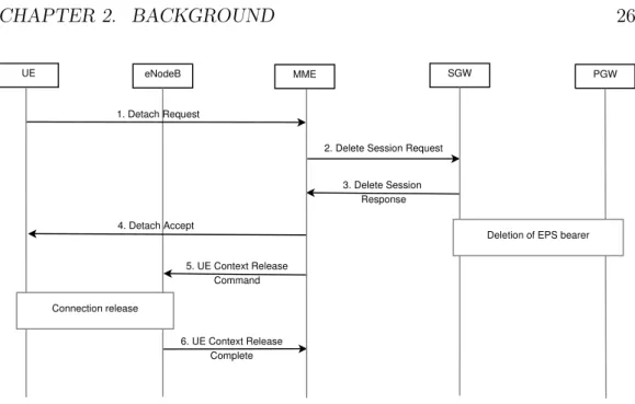
A detach procedure is used by the UE to disconnect from the EPS net-work [17]. In this thesis, we only consider the explicit detach procedure initiated by the UE. Figure 2.7 presents the call flow for the detach proce-dure. A brief description of the call flow and its important messages is as follows:
1. The UE sends aDetach Request over NAS, which includes the UE’s EPS mobile identity (either GUTI or IMSI) and a switch off indicator. The switch off flag is set if the UE initiates a detach due to the device switching off.
UE eNodeB MME SGW PGW HSS
1. Attach Request
2. Attach Request
3. Authentication and Security
6. Create Session Request 7. Create Session Request 8. Create Session Response 9. Create Session Response
4. Update Location Request
5. Update Location Ack
10. Initial Context Setup Request / Attach Accept 11. Attach Accept 12. Radio reconfiguration 13. Initial Context Setup Response 14. Attach Complete 15. Modify Bearer Request 16. Modify Bearer Response
Figure 2.6: Call flow for initial attach procedure
2. The MME sends a Delete Session Request to the SGW for each EPS bearer to be deactivated for the particular UE.
3. The SGW releases the EPS bearer context information and initiates the deletion of the bearer on the PGW. It then acknowledges the MME with a Delete Session Response.
4. The MME acknowledges the UE with aDetach Accept if the switch off indicator was not set in the initial Detach Request.
5. The MME also tears down the S1 signalling connection between the MME and eNodeB for the UE by sending a UE Context Release Command.
UE eNodeB MME SGW
1. Detach Request
2. Delete Session Request
3. Delete Session Response 4. Detach Accept PGW 5. UE Context Release Command 6. UE Context Release Complete Connection release
Deletion of EPS bearer
Figure 2.7: Call flow for detach procedure
6. The eNodeB confirms the tear down of the S1 signalling connection by sending a UE Context Release Complete.
2.4
Network Functions Virtualisation (NFV)
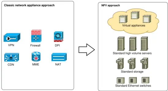
Network Functions Virtualisation (NFV) involves the implementation of net-work functions as software modules that can run on commercial off-the-shelf hardware. Currently, network elements run vendor-specific software on pro-prietary hardware. Typically, each network function is deployed on a ded-icated hardware device. NFV aims to decouple the software from the un-derlying hardware by leveraging IT virtualisation technologies. With this approach, network functions will be implemented as Virtualised Network Functions (VNFs) which can be run on standard hardware in the form of Virtual Machines (VMs). Figure 2.8 illustrates the concept of NFV.
NFV was first introduced in 2012 in an introductory white paper [41] published by the NFV Industry Standards Group (ISG), comprising of seven leading telecom operators within the European Telecommunications Stan-dards Institute (ETSI). By 2015 the number of members has increased to more than 270 companies, including 37 telecommunication operators, net-work equipment providers and IT vendors. The NFV ISG has also published several specifications including those for architectural framework, NFV in-frastructure requirements, and management and orchestration.
VPN Firewall DPI
CDN MME NAT
Standard Ethernet switches Standard storage Standard high volume servers
Classic network appliance approach NFV approach
Virtual appliances
Figure 2.8: NFV approach to virtualise traditional network elements, such as Virtual Private Network (VPN), firewall, Deep Packet Inspection (DPI), Content Delivery Network (CDN), MME, Network Address Translation (NAT), etc. (Adapted from [41])
Among the nine use cases identified by the NFV ISG [42], this thesis focuses on the use case “Virtualization of Mobile Core Networks and IMS (IP Multimedia Subsystem)”. Mobile network operators have to keep up with increasing demands from growing mobile data traffic and increasing number of connected devices. Although radio access technologies have evolved to allow faster data rates, the highly centralised core network and dependency on proprietary hardware still constrain network operators from taking full advantage of higher transmission rates [60]. Moving to the cloud computing paradigm allows network operators to decentralise their network architecture and minimise investments in hardware solutions [59].
2.4.1
Benefits
The application of NFV in EPC offers several benefits to network operators as discussed below:
• In present-day networks, significant costs are incurred in acquiring and installing hardware equipment for different network functions. In the NFV approach, different VNFs can be aggregated and run on the same standardised hardware platforms, thereby maximising utilisation of in-frastructure and reducing energy consumption.
• NFV aims to spur service innovation in the field of telecommunications, as new services implemented as software modules can be deployed faster in the network. Currently the installation of hardware equipment in the network involves a build-integrate-deploy cycle [41] which requires highly qualified personnel to install, test and manage the devices. NFV reduces the time required for services to be deployed in the network as software-based developments have a shorter integration cycle.
• NFV can also assist network operators in dimensioning their networks. Core network elements are usually overprovisioned in order to han-dle potential increases in traffic. However, this results in components being unused or underutilised during periods of low activity. By lever-aging IT virtualisation, operators can increase the number of virtual instances when subscriber traffic increases and remove these instances when no longer required. Thus, capacity can be dynamically increased or decreased allowing operators to react to real-time traffic patterns.
• NFV offers the additional benefit of improved flexibility, as VMs can be deployed in a location convenient for the operator. VMs can be deployed closer to the end user to reduce latency and improve overall Quality of Experience (QoE) for the user. For example, [59] introduces the concept of a Follow-Me-Cloud, wherein data and network services intelligently follow a user’s movement. This allows for an optimal end-to-end service for the user.
2.4.2
Challenges
Although NFV offers several benefits, the virtualisation of network functions in a mobile network brings a unique set of challenges, different from standard IT virtualisation:
• Mobile network operators need to simultaneously meet requirements of high availability and very low latency. An MME that has to be 99.999% available can go offline for only less than 6 minutes per year [31].
• There is a possibility of performance degradation when moving soft-ware from proprietary to standard hardsoft-ware. EPC networks are built on top of highly specialised hardware. This hardware generally of-fer features such as acceleration engines and dedicated processors for packet forwarding [41, 60]. The challenge is to provide the same level of performance as standardised hardware through software technologies and by using the appropriate hypervisor.
• Another pertinent issue is that of security. Execution of multiple VNFs over the same infrastructure requires that these instances be isolated from each other and the data stored on shared resources be secure. This is more problematic when different vendors are involved in the deployment of the virtualised elements.
• NFV also introduces new management and orchestration challenges in the network. It is now required to keep track of VNF instances, move VMs when required, allocate hardware resources during scaling operations, instantiate VNFs at the appropriate location depending on QoS requirements, and determine faults in VMs as well as underlying infrastructure.
2.5
Architecture of virtualised EPC network
elements
With the convergence of cloud computing technologies and mobile networks, architectures of traditional network elements need to be re-invented to take advantage of the benefits of cloud computing. These features include being able to leverage the cloud platform for scalable infrastructure, handle scaling events without downtime or user experience degradation, and ability to scale proactively [67]. Network functions are designed for a static deployment in mobile networks and not for the dynamic environment of cloud computing where frequent scaling and redistribution activities can occur [59]. Further-more, it is important to consider the resilience and adaptability of Virtualised Network Functions (VNFs) in this dynamic environment. This section de-scribes architecture choices for virtualised elements in the EPC.
2.5.1
1:1 mapping
The simplest architecture for a virtualised EPC element is where its entire functionality is mapped to a single VM. This corresponds to a 1:1 mapping [8]. In this architecture, the design of the state machine of the virtualised element and interfaces to other network devices remain the same as in cur-rent hardware-based solutions. The advantage of a 1:1 architecture is that it is conceptually similar to existing implementations and follows the same deployment model of one function on one device [8]. This allows for rapid and easy migration to the NFV approach for EPC networks.
However, this approach has several disadvantages as outlined in [8]. To explain these disadvantages, we consider the case of a 1:1 mapping for an
MME. First, in a cloud computing domain, a new VM is created when the number of subscribers increases beyond the running capacity of an existing MME. In such a case, each newly created virtual MME needs to be con-figured with EPC-specific parameters, including interfaces to other network elements and a globally unique identifier for the MME. Handling the dynamic configuration of many VMs may result in scalability issues for the Element Management System (EMS). Furthermore, the addition of a new MME re-quires informing other elements in the network. For instance, all eNodeBs serving an MME pool area have to be informed of the creation of a new MME. Secondly, once the VMs are configured and serving subscribers, they maintain information of active subscribers in their local storage. In case a VM is no longer required, for example due to reduction in subscriber num-bers, a 1:1 mapping does not allow for a simple shutdown of the VM as active sessions will be affected. Although 3GPP specifications [17] allow transfer-ring subscriber information between MMEs in an MME pool area through Overload or S1 Handover with MME Relocation procedures, this results in signalling overhead.
2.5.2
1:N mapping
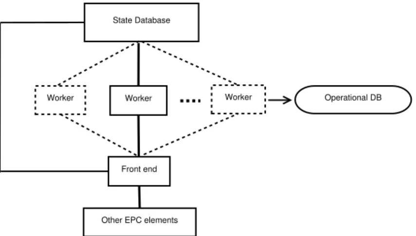
A second architecture option is a 1:N mapping [8] as depicted in Figure 2.9. In this architecture, a network element is divided into three components -front end (FE), worker and state database. This follows from the three-tier architecture of web applications. The three components are described as follows: State Database Worker Worker Worker Front end Operational DB
Other EPC elements
• The FE maintains communication interfaces towards other elements in the network and balances requests to the workers, which handle the actual processing logic.
• Workers are stateless components which actually implement the func-tionality of the network element. Each worker is configured with the same network paramaters and is made stateless by moving user state information to the state database. The workers are logically connected to an operational data storage for storing log files and information re-lated to basic operations and troubleshooting.
• The state database maintains user state information.
In this thesis, we choose this architecture for the MME due to the sev-eral benefits it offers [8, 60]. First, all workers are configured with the same parameters and in combination with the FE, can be visualized as a single network element. This simplifies operations and management functions as only one configuration scheme is required. Secondly, the workers being state-less can be independently started or stopped, i.e. scaled in or out, without impacting connected users. The change in state of the worker has to be informed only to the FE and is transparent to external network elements. Thirdly, a more granular control of load balancing is possible with this ar-chitecture which results in better utilisation of the processing capabilities of workers. Current load balancing techniques are based on weight factors in DNS queries or S1AP messages between the MME and eNodeB [17]. Dy-namic changes of DNS records and increased S1AP messaging can be avoided with this architecture. Finally, this architecture leads to greater resilience as the stateless workers can fail with minimal effect on the user sessions.
While this approach offers several advantages, the FE could become a bottleneck for processing as all messages need to pass through the FE to the appropriate worker. A solution to circumvent this could be to implement multiple front end nodes. However, this increases complexity of the archi-tecture and also requires appropriate load balancing procedures for the front end itself. Also, scaling the FE results in new IP addresses, which can lead to service interruption [58]. There may also be an increase in latency due to increased number of nodes through which each message has to pass [60]. Accessing the state database can result in increased network and CPU util-isation [68]. Additionally, synchronutil-isation issues between different virtual components in this architecture can result in serialised access of the state database, which can cause lowered system performance [60].
2.5.3
N:1 mapping
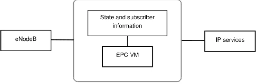
In an N:1 mapping, all elements of the EPC network (such as MME, SGW, PGW, HSS) are virtualised and merged into a single virtualised compo-nent [8]. A subscriber or a group of subscribers is served by one EPC VM, which maintains subscriber state information in local storage. The only ex-ternal interfaces for this component are towards the eNodeB and an exex-ternal data network as depicted in Figure 2.10. Since the remaining 3GPP elements and interfaces are internal to the EPC VM, it is possible to optimise the pro-cessing and sending of messages between these internal components. Thus, this architecture option allows for a highly optimised software implementa-tion of the complete EPC with low processing delays and minimal interfaces [60].
State and subscriber information
EPC VM
eNodeB IP services
Figure 2.10: N:1 architecture diagram
However, the N:1 architecture option presents scalability problems for the EMS and other external components when maintaining and configuring a large number of EPC VMs. Secondly, the virtualisation of the HSS as part of the EPC VM means that the HSS handles only a part of the subscriber information. Thus, subscriber data management becomes complicated with this architecture. Thirdly, this architecture no longer allows for multi-vendor solutions (wherein different elements in the EPC are developed by different equipment vendors) and the entire EPC has to be provided by a single ven-dor [60].
2.5.4
N:2 mapping
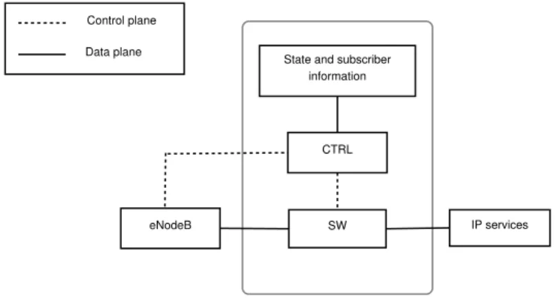
An N:2 architecture is similar to the N:1 architecture, but with the control and data plane functionalities handled by different components. Figure 2.11 presents the N:2 mapping. There are three components in this architecture:
• A control (CTRL) component implements the complete control plane functionality of the EPC. This includes the functionality of MME, HSS and control plane functions of the SGW and PGW.
• A switch (SW) handles forwarding of user data packets, i.e. the user plane functions of the SGW and PGW. This component need not be vir-tualised and can thus utilise the high performance of hardware switches.
• A state database maintains the user state information, implemented either as an SQL or NoSQL database.
State and subscriber information
CTRL
eNodeB SW IP services
Control plane Data plane
Figure 2.11: N:2 architecture diagram
This architecture option arises from the difference in requirements of data plane and control plane processing [60]. The control plane functionality de-mands low latency and fast computation, but the throughput requirements are not very high. However, the data plane functionality demands high data throughput, which can be provided by specialised hardware or with appro-priate virtualisation technologies. The advantages and disadvantages of the N:2 mapping are similar to that of the N:1 architecture. An implementation of the N:2 architecture is discussed in [9].
2.6
Related work
Virtualisation and distributed design for network elements in the EPC and IMS are active areas of research. In this section, we first review existing literature in distributed design. We then describe the concept of a telecom-munication cloud and review research in this area.
2.6.1
Distributed design for network elements
The authors of [25, 26] provide a design for a distributed MME with a reliable object store to save long term user state information. This architecture
separates the processing capabilities of the MME (distributed over several replicas) from the user state storage system. A one hop Distributed Hash Table (DHT) is used for membership management within the MME replicas. By moving the user information out of the MME replicas, they operate as independently as possible. This allows for scaling out or scaling in of replicas when required and migration of user states depending on the locality of the user. An elastic core architecture is described in [64], which separates state processing for virtualised network functions from the state information stored in a database. Software-Defined Networking (SDN) is used to flexibly allocate new resources for virtualised elements. The authors further analyse the application of this architecture to a virtualised IMS. [58] presents the application of elastic core architecture to an MME, which is able to provide session continuity during scaling operations.
IMS is an architectural framework designed to deliver multimedia services over IP protocol [21]. [34] discusses the application of different architecture patterns (including 1:1 and 1:N described in Section 2.5) to a virtualised IMS. Clearwater [2] is an open-source implementation of the IMS designed to run on the cloud. In this design, long term state information is moved out of the processing nodes to an external data store. Communication between the front-end and back-end components are enabled using Representational State Transfer (REST) commonly used in web applications. [50] presents an IMS distributed over nodes configured in a DHT overlay network. This architecture increases the robustness of the network elements and enables self-organisation of component nodes.
2.6.2
Moving telecommunication systems to the cloud
The convergence of cloud computing and mobile networks is often referred to as the telco cloud or carrier cloud. An overview of the telco cloud, its ben-efits, and challenges for implementation are provided in [10, 31, 59–61, 69]. The authors of [47] discuss the benefits and challenges of implementing vir-tual EPC networks. The authors propose grouping of virvir-tualised elements in order to reduce control plane signalling between these elements. For example, the MME can be grouped with a front end for the HSS, thereby reducing net-work interactions. To build resilience and scalability into telecommunication systems, [51] proposes an architecture wherein a replica of each processing node is created and stored on other servers. This architecture allows for dynamic resource control and high availability. [48] discusses the feasibility of dynamic scaling in telco clouds. The authors describe a new architecture and protocols to migrate user sessions between stateful nodes in the IMS.
are seen as key enablers for the telco cloud. SDN decouples the control and data plane and uses a centralised controller to make forwarding deci-sions. [38] presents a testbed architecture combining both NFV and SDN to demonstrate their applicability for future 5G networks. SDN can simplify the transport layer in mobile core architectures [38] and allow for flexibly controlling the network through software [64].
2.7
Summary
This chapter has introduced the background concepts to understand the work presented on the implementation of a virtualised distributed MME in EPC networks. We have therefore introduced three broad topics.
First, we have discussed the EPC, which forms the core of LTE networks. We have reviewed the EPC architecture and discussed the functionality of each network element to provide mobile data services to end users. We have then discussed in detail the control plane responsibilities of the MME. We have described two important interfaces; the S1-MME between the MME and the eNodeB, and the S11 between the MME and the SGW. We have also dis-cussed the state information maintained by the MME on its local storage. Furthermore, two EPC procedures, the initial attach and UE-initiated de-tach, have been explained as these have been used to evaluate the behaviour of the distributed MME.
Secondly, we have introduced NFV, which is the virtualisation paradigm enabling network functions to be deployed on the cloud. While NFV leads to significant cost savings and allows network operators to harness the benefits of cloud computing, it also presents challenges in ensuring availability and performance.
Lastly, we have reviewed the architecture choices for virtualised elements in the EPC in order to address some of the challenges of NFV. We have identified the 1:N mapping or three-tier architecture to be most beneficial for the MME. This architecture enables the MME to scale efficiently as well as to be resilient to the failure of stateless workers. Furthermore, we have reviewed existing literature and identified similar examples of distributed architectures for IMS and MME. In addition to demonstrating the benefits of the new architecture, we aim to compare the distributed design to that of the original MME through an evaluation of latency during attach and detach procedures.
Chapter 3 describes our implementation of the three-tier architecture for the MME.
Implementation
This thesis modifies and extends the MME software developed by Vicent Ferrer as part of his Master’s thesis [45]. The original software corresponds to a 1:1 mapping or standalone architecture, wherein the entire MME func-tionality is implemented on a single VM. This design has disadvantages when deployed on the cloud, which are discussed in Section 2.5.1. We re-design the original MME software to correspond to a three-tier architecture or 1:N mapping described in Section 2.5.2. This new distributed architecture allows the MME to harness the benefits of cloud computing in terms of scalability and elasticity.
This chapter discusses the implementation details of the new architecture for the MME. Section 3.1 first provides an overview of the system design. Sections 3.2, 3.3 and 3.4 describe the functionality and implementation of the three tiers. In each of these sections, we also discuss the trade-offs between design choices made and considerations for further improvement.
3.1
Overview of system
Figure 3.1 depicts the overall system including the new design for the MME. The MME consists of three main components – a front end (FE), one or more workers and a state database. The FE behaves as an intelligent proxy and maintains interfaces to other elements in the EPC network. The workers are responsible for the actual functional processing in handling user mobility and sessions. The UE context for each user is stored in the state database, thereby making the workers stateless. Thus, the workers can be easily scaled out or scaled in depending on network load. This also makes the MME resilient to the failure of workers as user state information is saved on the state database. Any worker with access to the UE context can take over the
State database
Worker Worker Worker
Front end MME Collocated SGW and PGW Internet OpenStack load balancer eNodeB UE S1-MME S1-U S11
Figure 3.1: Architecture of system processing in case of failures.
A combination of the three tiers represents a single MME to external ele-ments such as the eNodeBs and SGW/PGW. The workers and state database are transparent to other EPS entities, as all interfaces to external elements terminate at the FE. In addition to the EPS elements (eNodeB, MME, SGW, PGW), the system includes an OpenStack load balancer developed as part of [23]. This component is responsible for creating and deleting worker VMs on OpenStack. The functionality of the load balancer corresponds to the roles of the VNF Manager and NFV Infrastructure Manager [43].
3.2
Design of front end (FE)
The main functions of the FE are to:
1. Maintain 3GPP standardised interfaces towards other EPC network elements – In our system, the FE maintains an S1-MME interface to-wards eNodeBs and an S11 interface toto-wards SGWs.
2. Balance requests between worker nodes – Our FE design employs a sim-ple round-robin balancing scheme to distribute new requests to worker nodes.
3. Inform the OpenStack load balancer when new workers are required to be created or deleted
In order to realise the first two functions, the FE needs to correctly for-ward S1AP messages between workers and eNodeBs, and GTP messages
between workers and SGWs. To identify the MME worker, eNodeB and SGW responsible for handling a particular user session, the FE maintains a mapping which associates the UE with each of these elements. The FE determines the UE identity based on Information Elements (IEs) present in the message to be forwarded. Sections 3.2.1 and 3.2.2 describe this mapping in further detail. Section 3.2.3 discusses the interface between the FE and OpenStack load balancer.
3.2.1
Forwarding S1AP messages
In our design, the IEs used to identify a UE over the S1-MME interface are the MME UE S1AP ID and eNodeB UE S1AP ID in S1AP messages, and the IMSI in NAS messages. The MME UE S1AP ID and eNodeB UE S1AP ID are unique identifiers for a UE assigned by the MME and eNodeB respectively. When a UE first attaches to the LTE network, it identifies itself with its IMSI in the “Attach Request” message. This message also contains the eNodeB UE S1AP ID. The FE chooses an appropriate worker to forward the request to and maps the UE to the selected worker, as well as to the eNodeB from which the request was received. Once the worker assigns an MME UE S1AP ID, all further S1AP messages to and from the UE contain this IE. Subsequently the FE can appropriately forward messages between the eNodeB and worker node based on the the S1AP IDs.
3.2.2
Forwarding GTP messages
All control plane messages between the MME and SGW related to a specific UE are sent over a unique GTP tunnel. Each endpoint maintains a Tunnel Endpoint ID (TEID), an IP address and UDP port number to identify the tunnel. During establishment of PDN connectivity, the MME worker first sends a “Create Session Request” which includes the UE’s IMSI and a TEID generated by the worker. We refer to this TEID as the MME TEID. On receiving this message, the FE saves the mapping between the UE and MME TEID. It then chooses an SGW and forwards the message to it. In the corresponding “Create Session Response”, the SGW includes its own TEID (referred to as the SGW TEID) and sets the receiver TEID as the MME TEID. Upon receiving this message, the FE forwards it to the worker based on the mapped MME TEID. It also saves the SGW TEID to the UE’s mapping structure. The FE now uses the GTP TEIDs present in all subsequent GTP messages to identify the appropriate SGW and worker.
[15] requires that GTP sequence numbers are maintained per sending queue, i.e. for each triplet of local IP address, local UDP port and remote
peer’s IP address. Thus, the FE appropriately updates the sequence number in each outgoing GTP message. To summarise, Table 3.1 lists the messages in the implemented call flow procedures and the corresponding S1AP and GTP IEs used to identify the UE.
3.2.3
Communicating with the OpenStack load
bal-ancer
The FE maintains a long-lived TCP connection to the HTTP server of the OpenStack load balancer. When the number of incoming attach requests per worker goes above or below a certain threshold, the FE sends an HTTP request to the load balancer requesting either the creation or deletion of a worker. Creating a new worker corresponds to a scaling out operation. Once a new VM is created and the worker is active, it initiates an SCTP association to the FE. The FE then adds the newly created worker to its list of available workers and forwards new requests to it. The scaling in operation, i.e. deleting workers, requires more careful consideration, so as not to effect any on-going procedures. When the incoming call rate goes below a certain threshold, the FE first marks a worker for deletion and stops forwarding any new procedure requests to this node. However, messages from ongoing procedures are still forwarded to and from this worker so as not to disrupt the user session. The FE then waits for a configurable time period to allow ongoing call flows to complete and the state information for the UEs to be written to the state database. After this time period has elapsed, the FE sends an HTTP delete request to the load balancer with the IP address of the worker marked for deletion.
3.2.4
Design considerations
The performance of the overall MME is dependent on the processing capa-bilities of the FE. The FE could become a potential bottleneck and single point of failure in the system. In a similar design for a virtualised IMS, [48] proposes deploying multiple Client Elasticity Gateways (CEGs) close to the client. The CEGs are similar in functionality to the FE and such a solution can be used for the FE as well. Additionally, the FE is a stateful entity as it maintains a mapping structure to forward messages between the worker and UE/SGW. To avoid maintaining this information, [58] proposes creating groupings of IMSIs based on hash value and assigning a worker instance to a group of UEs. However, this limits the scalability of the worker nodes, as there should always be atleast one worker available to serve each group of UEs. An alternative solution could be to have the FE query the state
Message Protocol Information Elements (IEs) present to identify UE
Attach procedure
Attach Request S1AP eNodeB (eNB) UE S1AP ID
NAS IMSI
Authentication Request
S1AP eNB UE S1AP ID, MME UE S1AP ID Authentication
Response
S1AP eNB UE S1AP ID, MME UE S1AP ID Create Session
Request
GTP TEID to send to = 0 (SGW TEID un-known),
IMSI,
MME TEID Create Session
Response
GTP TEID to send to = MME TEID, SGW TEID
Attach Accept S1AP eNB UE S1AP ID, MME UE S1AP ID
NAS GUTI
Initial Context Setup Response
S1AP eNB UE S1AP ID, MME UE S1AP ID Attach
Com-plete
S1AP eNB UE S1AP ID, MME UE S1AP ID Modify Bearer
Request
GTP TEID to send to = SGW TEID Modify Bearer
Response
GTP TEID to send to = MME TEID Detach procedure
Detach Request S1AP eNB UE S1AP ID, MME UE S1AP ID NAS IMSI or GUTI
Delete Bearer Request
GTP TEID to send to = SGW TEID Delete Bearer
Response
GTP TEID to send to = MME TEID UE Context
Re-lease Command
S1AP eNB UE S1AP ID, MME UE S1AP ID UE Context
Re-lease Complete
S1AP eNB UE S1AP ID, MME UE S1AP ID
Table 3.1: Important IEs present in messages exchanged during attach and detach procedures
database to identify the worker currently processing a particular UE. This requires more careful design so as to minimise any increase in latency due to database queries. Also, in our current prototype, the MME does not per-form NAS ciphering and integrity protection. This requires further logic to be implemented on the FE.
3.3
Design of worker
The design of the worker follows the same principles of the original MME software and is described in [45]. The worker represents the actual func-tionality of the MME and handles the processing of call flows. Each worker maintains two separate interfaces towards the FE, one for S1AP messaging and the other for GTP messaging. The HSS is implemented as a MySQL database and is co-located with the worker. Thus, the S6a interface is not realised. The open-source C client library hiredis1 is used by the worker to interface to the Redis server.
3.3.1
Attach procedure
This section describes the implementation of the attach procedure on the worker. The procedure is similar to that described in Section 2.3.1. In order to make the workers stateless, we introduce additional messages to store the UE context on the state database. Figure 3.2 shows the attach call flow implemented in this thesis and can be compared to that in Figure 2.6. For simplicity, the FE is not depicted in Figure 3.2 as it simply forwards messages between the eNodeB and worker. To minimize processing time, the state information is not stored at each step of the call flow but only towards the end of the procedure. The worker stores the UE context at step 8, on receiving a successful “Create Session Response” from the SGW. At this point, the user is considered to be in the registered state and successfully attached to the LTE network.
3.3.2
Detach procedure
Once the UE context has been stored in the state database, any worker can handle further procedures for the registered UE after retrieving the context information from the database. For example, in the detach procedure de-picted in Figure 3.3, the worker first queries the state database to retrieve
1
UE eNodeB MME worker SGW PGW State DB
1. Attach Request
2. Attach Request
3. Authentication and Security
4. Create Session Request 5. Create Session Request 6. Create Session Response 7. Create Session Response 9. Initial Context Setup Request / Attach Accept 10. Attach Accept 11. Radio reconfiguration 12. Initial Context Setup Response 13. Attach Complete 14. Modify Bearer Request 15. Modify Bearer Response 8. Store UE context
Figure 3.2: Attach call flow implemented on worker
the UE context. Based on the state information, the worker can now handle the processing of the user session and detach the subscriber.
3.3.3
Design considerations
Storing the UE context at each step in the call flow can help to increase the resilience of the MME. In our current implementation, if a worker fails during the processing of a call flow, the procedure has to be re-initiated. However, storing the context at each step leads to increased CPU utilisation and network overhead with external database queries. By choosing to store UE context only after a call flow is complete, there is a trade-off between low latency with fewer database queries and decreased resilience. [58] provides
UE eNodeB MME worker SGW 1. Detach Request 3. Delete Session Request 4. Delete Session Response 5. Detach Accept PGW 6. UE Context Release Command 7. UE Context Release Complete Connection release State DB
Deletion of EPS bearer 2. Retrieve UE context
Figure 3.3: Detach call flow implemented on worker
an analysis of the impact of losing state information during a call flow. For example, if state information is lost during an attach procedure, the pro-cedure has to be re-executed by the UE. Similar analysis is carried out for other 3GPP procedures. In [51], the authors propose synchronisation of ses-sion states for a distributed IMS only at certain stages, so as not to degrade performance while maintaining an acceptable level of call dropping proba-bility. In a three-tier architecture for a virtualised IMS, [68] proposes using a cache on the client (equivalent to the worker, in our case) on which the application stores serialized data. The state information is eventually stored in the state database. Read operations first attempt to retrieve data from the cache before querying the state database. With this caching mechanism, some of the negative effects of moving long-term state information out of the worker can be reduced.
3.4
Design of state database
The state database is the third tier in the MME architecture and stores state information for each UE attached to the MME. This state information is referred to as the UE context and is described in Section 2.2.2. Three options for implementing the state database are [8]:
• Centralised database – A centralised database can be used to serve a single data center where virtual MME instances are deployed.
• Distributed database – A distributed database or data store can be deployed independent of the virtual instances.
• Distributed filesystem – A distributed file system such as Ceph2 can be used to store subscriber information. [9] provides details of the implementation and evaluation of its suitability for storing shared state information for virtualised EPC elements.
A distributed design for the state database is possible because the state information for each user is small (in the order of a few kilobytes) and high bandwidth links are available in mobile backhaul networks [26]. We choose a NoSQL data store due to its simplicity of use, high availability and scalable nature [35]. The UE context can be stored in a NoSQL data store as a key-value pair, with the key being a unique identifier. Additionally, only one client (the worker in our case) will access the state information for a particular UE at a time. This further allows for the use of a distributed data store without the need for exclusive access control [68]. There are several distributed data stores available for use, including Apache Cassandra3, Riak4
and memcached5.
3.4.1
Redis cluster
We choose Redis to implement the state database. Redis is an open source, in-memory key-value data store6. The in-memory feature ensures that it
operates with very low latency. The Redis cluster feature (introduced since Redis 3.0 [5]) allows for sharding data across multiple nodes. Furthermore, its simplicity of use and availability of a client library in C [4] make it an ideal choice.
Communication between the MME worker (Redis client) and Redis server takes place over a TCP connection and uses Redis Serialization Protocol (RESP) [7]. The communication follows a Request/Response pattern. A Redis cluster uses asynchronous replication, which means that the cluster responds to a write operation before it is replicated on a slave. Although there is a small window during which a Redis cluster may lose writes [5] and thereby user state information, this loss can be handled by existing procedures in 3GPP standards. For instance, 3GPP standards are designed to allow for recovery of UE context information or re-initiation of procedures
2 http://ceph.com 3 http://cassandra.apache.org 4 http://basho.com/riak 5 http://memcached.org/about 6 http://redis.io
![Figure 2.1: Evolution of mobile network architecture [13]](https://thumb-us.123doks.com/thumbv2/123dok_us/10127900.2913571/16.892.172.728.172.450/figure-evolution-of-mobile-network-architecture.webp)
![Figure 2.3 shows the protocol stack for communication between the UE, eNodeB and MME. We do not discuss the radio interface protocol stack for the LTE-Uu interface, details of which can be found in [20].](https://thumb-us.123doks.com/thumbv2/123dok_us/10127900.2913571/19.892.207.690.703.911/figure-protocol-communication-discuss-interface-protocol-interface-details.webp)