Wideband acoustic activation and detection of droplet
vaporization events using a capacitive micromachined
ultrasonic transducer
AnthonyNovell,1Christopher B.Arena,1OmerOralkan,1,2and Paul A.Dayton1,a)
1
Joint Department of Biomedical Engineering, The University of North Carolina and North Carolina State University, Chapel Hill, North Carolina 27599, USA
2
Department of Electrical and Computer Engineering, North Carolina State University, Raleigh, North Carolina 27695, USA
(Received 14 October 2015; revised 2 March 2016; accepted 4 April 2016; published online 23 June 2016)
An ongoing challenge exists in understanding and optimizing the acoustic droplet vaporization (ADV) process to enhance contrast agent effectiveness for biomedical applications. Acoustic signatures from vaporization events can be identified and differentiated from microbubble or tissue signals based on their frequency content. The present study exploited the wide bandwidth of a 128-element capacitive micromachined ultrasonic transducer (CMUT) array for activation (8 MHz) and real-time imaging (1 MHz) of ADV events from droplets circulating in a tube. Compared to a commercial piezoelectric probe, the CMUT array provides a substantial increase of the contrast-to-noise ratio.VC 2016 Acoustical Society of America.
[http://dx.doi.org/10.1121/1.4953580]
[CC] Pages: 3193–3198
I. INTRODUCTION
Ultrasound contrast agents, consisting of gas-filled microbubbles, have been introduced to aid in imaging the vasculature by enhancing the backscattered signal from blood.1Over the last two decades, there has been significant progress towards developing stable, highly echogenic micro-bubbles, which permit an increase in scattering that persists for several minutes.2 Several microbubble formulations, comprised of gas cores stabilized with albumin, lipid, or polymer shells, have been approved for diagnostic applica-tions including echocardiography (e.g., myocardial perfusion assessment)3 and radiology (e.g., characterization of pathological lesions).4Microbubbles are usually composed of perfluorocarbon cores because they are non-toxic, chemi-cally and biologichemi-cally inert compounds making them attrac-tive for medical applications. Many efforts are still being undertaken to understand and exploit the specific character-istics of microbubbles5in order to isolate their acoustic sig-nature from that of tissue and improve the contrast-enhanced image quality of vasculature. Microbubble contrast agents are also providing promising avenues for therapeutic applications, such as thermal ablation enhancement,6 throm-bolysis,7or drug and gene delivery.8However, microbubble circulation remains restricted to the vascular system, because their size (i.e., 1–10lm in diameter) prevents them from passing through endothelial tight junctions. As a result, microbubbles are unable to reach extravascular targets. Gas diffusion and clearance by the body also limits the circula-tion lifetime of microbubbles and decreases their potential for long-term accumulation in tumors and theranostic applications.9
To address these challenges, liquid perfluorocarbon nanodroplets have been proposed as a potential extravascular ultrasound contrast agent.10–15 It is hypothesized that drop-lets within the size range of a few hundred nanometers can extravasate through leaky microvasculature and accumulate in the tumor interstitial space. Once extravasated, the liquid core of nanodroplets can be vaporized into a gas during the rarefactional cycle of an ultrasonic pressure wave [i.e., acoustic droplet vaporization (ADV)].16This leads to a rapid increase in core volume resulting in the production of micro-bubble contrast agents having contrast properties similar to those currently used for diagnostic applications.17,18 Moreover, the mechanical perturbations produced during the ADV process could induce bioeffects on nearby cells and enhance localized drug delivery.19To date, only few studies have investigated the bioeffects related to ADV. Chen and team have observed that ADV can enhance blood brain bar-rier permeability20 and other mechanical bioeffects have been observed by Kanget al.21In theirin vitrostudy, Kang
et al.reported vessel wall disruption when ADV was associ-ated with inertial cavitation (for rarefactional peak pressure >8 MPa). Nevertheless, the influence of ADV process (e.g., cavitation, microstreaming) on the surrounding tissue is not well known and further investigations are still required to precisely evaluate the ADV-induced bioeffectsin vivo.
The ADV event exhibits a unique acoustic signature that can be differentiated from tissue and microbubble contrast agent responses.22 Ultra-high-speed camera observations published by our group demonstrated that this phenomenon is dictated by an overexpansion of the generated microbub-ble followed by exponentially decaying oscillations to final resting diameter.22 The long oscillations (>5 cycles) repre-sent the natural resonance of the generated microbubbles in the medium. Therefore, by examining the resulting acoustic
a)
signal, it is possible to determine physical properties of the contrast agents (e.g., size, shell material) and deduce infor-mation about the surrounding environment (e.g., ambient pressure, temperature, and viscosity).22 Monitoring the vaporization of droplets in real-time would be also beneficial for droplet-mediated therapy in order to visualize and control the location of the treated area.23
Very recently, a dual-frequency approach based on the “pulse high, listen low” scheme previously described by Sheeranet al.22has been validated for isolating and extract-ing the droplet vaporization events. Usextract-ing this approach, droplets are activated at high frequency (8 MHz) while the vaporization signal is detected by a second transducer cen-tered at low frequency (1 MHz). This technique, requiring the use of two mechanically scanned confocal piston trans-ducers, has been adapted to develop an imaging system for capturing droplet vaporization events and generating high-sensitivity, high-contrast images.24The large difference between the activation pulse frequency and the listening fre-quency results in a weak response from microbubbles and tissue.In vitroresults showed that ADV imaging was capa-ble of generating a contrast-to-tissue ratio (>18 dB), as good as standard contrast agent imaging techniques.24 Imaging ADV at low frequency has several advantages. First, the penetration depth is increased because of the weak attenua-tion of low-frequency droplet content in tissue. Addiattenua-tionally, the absence of non-linear propagation in tissue at the listen-ing frequency facilitates the detection of the vaporization signal. However, one drawback remains the poor resolution induced by the newly generated bubble ringing. Another major limitation lies in the requirement for two transducers to transmit and receive at separate frequencies.
Most of the piezoelectric transducers commercialized for imaging applications have a pulse-echo fractional bandwidth at 6 dB around 70%–80%. This limited bandwidth is not compatible with the “pulse high, listen low” scheme, which requires the use of a broadband transducer. For example, to transmit at 8 MHz and receive at 0.5 MHz, a transducer cen-tered at 4 MHz would require a fractional bandwidth higher than 185% which is currently not possible using piezoelectric technology. One option would consist of developing a dual-frequency array specifically designed for this application.
In this letter, we hypothesize that a capacitive micro-machined ultrasonic transducer (CMUT) linear array can be used to activate droplets at high frequency and image their vaporization signal at low frequency. CMUTs consist of a group of thin plates clamped at the edge and connected electrically in parallel. The fixed bottom electrode and the movable top electrode in this structure are separated by a sub-micron vacuum gap.25 An ac voltage is applied across the electrodes in order to generate an electrostatic force, which leads to plate vibrations and the generation of acoustic waves. Compared to traditional piezoelectric technology, CMUTs are known for having a fractional frequency band-width usually wider than 100%.26 Therefore, CMUT tech-nology is particularly attractive for wideband imaging applications such as photoacoustic imaging27 or contrast agent imaging,28or as a hydrophone.29In a previous study, Novell et al. demonstrated that a CMUT array could be
exploited to enhance the signal from contrast agents by recording the microbubble response at subharmonic and second harmonic frequencies simultaneously. In addition, the CMUT behavior in receive mode differs from transmit operation resulting in a wider bandwidth and a higher sensi-tivity at low frequency.30 This particular characteristic makes the CMUT ideal for ADV detection.
We investigated the performance of a linear CMUT array for activation and real-time imaging of vaporization signal emitted from droplets continuously infused through a tube. The sensitivity of the CMUT probe was characterized in transmit and receive modes and its potential for imaging ADV was quantified by measuring the contrast-to-noise ratio (CNR). The advantage of the CMUT technology for this spe-cific application was demonstrated by comparing the results to those obtained using a commercial piezoelectric linear array probe.
II. MATERIALS AND METHODS
Experiments were performed using a 128-element CMUT linear array probe (Vermon SA, Tours, France) with a pitch of 205lm and an elevational aperture of 5 mm. For this array, the static pull-in voltage was measured as 160 V. To estimate the bandwidth in transmit mode, CMUT ele-ments were excited using a broadband negative spike excita-tion emitted by a pulse-receiver (Model 5900PR, Olympus, Waltham, MA, USA). For this measurement, the CMUT was used in conventional-mode operation by applying a dc bias voltage of 90 V. The generated wave was then measured using a calibrated needle hydrophone (HNA-0400, Onda Corp., Sunnyvale, CA, USA) placed in a water-bath at 5 mm from the CMUT probe.
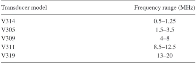
To determine the CMUT bandwidth in receive mode, five different single-element transducers (Olympus, Waltham, MA, USA) were used to cover a frequency range from 0.5 to 20 MHz. A list of the transducers and their operating frequency range is given in Table I. For each frequency, an arbitrary waveform generator (AFG 3101, Tektronix, Beaverton, OR, USA) and a 60 dB power amplifier (A-500, ENI, Rochester, NY, USA) were used to generate a 10-cycle sinusoidal wave at a pressure of 200 kPa at the focus (50 mm). Acoustic waves generated by single-element focused trans-ducers were then measured by the CMUT array placed at the focal distance and received signals were amplified (20 dB) using a broadband receiver (BR-640A, RITEC Inc., Warwick, RI, USA). A/D conversion was performed at a sampling rate of 100 MHz using a 14-bit waveform digitizer (PDA14, Signatec, Lockport, IL, USA) controlled by LabVIEW (National Instruments, Austin, TX, USA) to visualize and re-cord the received signals on a personal computer.
receive mode and the fractional bandwidth increased to 130%. Additionally, the CMUT sensitivity was maximum and relatively constant for frequencies from 0.5 to 5 MHz. Above 5 MHz, the sensitivity decreased slightly by 1.5 dB/ MHz. This decrease was mainly attributed to the attenuation of the silicone layer used to waterproof the CMUT array. We should mention that the attenuation of the silicone layer would also affect the performance in transmit mode by reducing the upper cutoff frequency and the bandwidth of the transducer.
For real-time droplet vaporization imaging, the probe was connected to a research ultrasound system (Verasonics Vantage platform, Kirkland, WA, USA). The bias voltage Vdc was selected at 140 V (i.e., around 90% of the static
collapse voltage) for optimal transmit CMUT operation. A five-cycle Gaussian pulse centered at 7.8 MHz was defined and transmitted through the 128 elements. Electronic focus-ing was used to generate a sufficient pressure able to vapor-ize the droplets at 20 mm. ADV imaging was evaluated at the three different peak negative pressures of 0.32, 0.90, and 1.20 MPa (corresponding to effective mechanical index, MIE,31of 0.11, 0.32, and 0.43, respectively). A dilute solu-tion of droplets (1:60 dilusolu-tion factor in PBS) was continu-ously infused into a microcellulose tube (223lm inner diameter) placed at 20 mm from the CMUT surface in a degassed water bath maintained at 37 C. A syringe pump (KDS210, kd Scientific, Holliston, MA, USA) was used to generate the fluid flow at 100lL min 1.
Lipid-coated octafluoropropane (OFP) droplets were formed using a condensation procedure previously described
by Sheeran et al.32In this approach, condensed droplets are produced from a precursor microbubble solution by decreas-ing the temperature and increasdecreas-ing the ambient pressure inside the containment vial. First, lipid-coated microbubbles were formulated by dissolution of 1,2-distearoyl-sn -glycero-3-phosphocholine (DSPC) and 1,2-distearoyl-sn-glycero-3-phosphoethanolamine-N-methoxy(polyethylene-glycol)-2000 (DSPE-PEG2000) in a 9:1 molar ratio, as previously described.33Lipids were purchased from Avanti Polar Lipids (Alabaster, AL, USA). The excipient solution was comprised of PBS, propylene glycol, and glycerol (16:3:1). Then, 1.5 mL of the resulting solution was pipetted into a 3 mL glass vial and the remaining headspace gas exchanged with OFP (low boiling point at 36.7C; FluoroMed, Round Rock, TX, USA). A Vialmix shaker (Bristol-Myers-Squibb, New York, NY) was used to generate a polydisperse popula-tion of OFP microbubbles via mechanical agitation. Condensed droplets were formed by immersing the micro-bubble vial in an isopropanol bath controlled to a temperature of approximately 10C for 1 min and 30 s. While remain-ing in the bath, the pressure was increased by connectremain-ing the vial to an adjustable high-pressure air source (the required pressure was on the order of 50 psi).
The CMUT array was evaluated for its potential to acti-vate droplets and detect vaporization signal. For each condi-tion, 10 frames composed of 128 lines were recorded and signal processing was performed to isolate the vaporization signal. Raw data were filtered from 0.5 to 2.5 MHz at a high frame rate using a 43 tap finite impulse response bandpass filter defined in the image processing algorithm from the Verasonics research scanner. Real-time images of acoustic droplet vaporization were displayed at a frame rate of 15 Hz. RF-data were analyzed in post-processing to calculate the CNR when a vaporization event was detected. The noise level was obtained by performing the experiment without any scatterers present within the tube. For comparison, a commercial 128-element piezoelectric probe (L11-5, ATL Philips Healthcare, Andover, MA, USA) was used to acti-vate and image the droplet vaporization events. This probe was chosen for its transmit performance (i.e., bandwidth from 5 to 11 MHz) close to the CMUT array. The same exci-tation waveform, beamforming, and signal processing were applied.
III. RESULTS
Images of a microcellulose tube containing a diluted solution of OFP droplets are shown in Fig.2for the various effective mechanical indexes. The first row corresponds to the images recorded using the L11-5 linear array while the images on the second row are obtained using the CMUT array. The dashed rectangles displayed for illustration in panels (a) and (d) indicate the position of the tube. At a low MIE of 0.11 (320 kPa), neither probe was able to detect a va-porization signal. Based on our prior data, this peak negative pressure is too weak to induce the vaporization of OFP drop-lets.22 Contrary to the piezoelectric probe [Fig. 2(b)], the CMUT array [Fig. 2(e)] was able to detect the vaporization signal form droplets at a MIE of 0.32 (900 kPa). In the TABLE I. List of the single-element transducers used for the
characteriza-tion of CMUT bandwidth in receive mode.
Transducer model Frequency range (MHz)
V314 0.5–1.25
V305 1.5–3.5
V309 4–8
V311 8.5–12.5
V319 13–20
image, the specific signal from ADV is characterized by a comet tail corresponding to the radial oscillation of the final microbubble. Increasing the pressure up to 1.2 MPa (MIE of 0.43) resulted in the activation of a larger number of droplets [Fig. 2(f)]. It is worth mentioning that using the L11-5, a very slight contrast enhancement can be observed at a MIE of 0.43. However, the extraction of the ADV signal from the noise level is problematic because of the poor sensitivity of the array at low frequency. Mean CNR (6standard devia-tion) measured from ten successive images are listed in Table II for piezoelectric and CMUT arrays. Compared to the L11-5, the CMUT array provided a 16.8 dB increase of the CNR at the highest MIE.
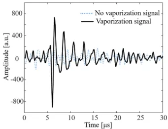
Figure 3 shows an example of a droplet vaporization signal detected by the CMUT array at an effective mechani-cal index of 0.32. As expected, the vaporization signal describes a rapid expansion followed by at least five oscilla-tion cycles induced by the generated bubble resonance. At this MIE, the sensitivity of the CMUT array is high enough to extract ADV signals from the noise level and observe sin-gle ADV events. This result suggests that the CMUT probe can be used to determine the ADV pressure threshold.
Examples of ADV signals recorded at a high MIE of 0.43 using the piezoelectric array (dotted line) and the CMUT array (solid line) are compared in Fig.4(a). Although ADV events can be detected using both probes, the signal from the L11–5 array is closer to the noise threshold, making its extraction more challenging. Corresponding frequency spectra are given in (b). As expected for the piezoelectric array, the frequency content of the ADV signal is masked by the noise level due to the lack of sensitivity of this probe at low frequency. On the contrary, the CMUT array allows the detection of a frequency response in which several peaks can be identified. The main frequency of this oscillation signal is
0.6 MHz, demonstrating that the CMUT array is able to detect signals even at very low frequency. Furthermore, two other peaks can be observed at 1.3 and 2.3 MHz. These peaks correspond to the vaporization of a smaller droplets as the oscillation frequency is inversely related to the final bubble size.22Indeed, at high MIE, the ADV signal is composed of multiple frequencies due to the activation of a larger range of droplet content. Therefore, the spectral approach is useful to determine the activated droplet content. Here, frequency peaks are observed between 0.5 and 2.5 MHz, corresponding to oscillation signals from bubbles between 5.4 and 1.1lm in radius according to the approximation of the Minnaert bubble resonance model given in Ref.22.
IV. DISCUSSION
The results reported here validate a new application of the CMUT technology for biomedical imaging. It is impor-tant to mention that the CMUT array used in this study was not specifically designed for ADV imaging. The specific behavior of the receive mode (i.e., the wide bandwidth and the high sensitivity at low frequency) results from the intrin-sic properties of the CMUT technology. Consequently, the CMUT array is not restricted to this single application and can efficiently operate in another standard imaging mode FIG. 2. Images of a microcellulose tube containing a diluted solution of OFP droplets using a piezoelectric array (a)–(c) and a CMUT array (d)–(f).
TABLE II. Contrast-to-noise ratio induced by droplet vaporization events (dB). NS means no vaporization signal detected.
Effective mechanical index Piezoelectric array CMUT array
0.11 NS NS
0.32 NS 6.362.3
0.43 2.762.0 19.562.3 FIG. 3. (Color online) Example of a droplet vaporization event observed at
such as B-mode, harmonic imaging or Doppler imaging, in parallel. For example, a simultaneous operation in B-mode and ADV imaging would allow a direct control of the probe positioning as the tissue response is suppressed in ADV imaging.
Furthermore, ADV imaging will not suffer from the CMUT nonlinear behavior. Indeed, upon certain excitation conditions (e.g., low frequency and high voltage), the acoustic wave emitted from the CMUT can be distorted by the presence of higher frequency components gener-ated by the transducer.34,35 Although this limitation is particularly deleterious for harmonic imaging, various approaches such as the use of predistorted waveforms,34,36 the development of specific pulse schemes35 or by the addition of a series impedance to the CMUT capaci-tance,37 have been recently proposed to suppress the undesired harmonic components. Here, the ADV signal will not be affected by nonlinear distortion because it is received well below the excitation frequency.
Although the detection of the ADV signal is particularly interesting for droplet characterization, the imaging approach still suffers from poor resolution induced by the long bubble oscillations following from the vaporization event. Recently, many super-resolution techniques based on the super-localization of spatially separated microbubble contrast agents have been described in the literature.38,39For example, the center of mass of isolated microbubbles can be calculated and extracted from an ultrasound image to construct super-resolved microbubble location density maps. This approach could be adapted to localize isolated ADV events.
V. CONCLUSION AND PERSPECTIVES
In this study, a CMUT array was successfully used to both induce acoustic droplet vaporization and detect acoustic signatures from vaporization events with a broadband per-formance unmatched by piezo transducers. With growing interest in contrast imaging utilizing wideband systems both for microbubble and phase change agent imaging,22,40 CMUT technology offers a promising technology for improved detection and signal separation as well as the de-velopment of image-guided feedback methods. Future work will include in vivo validation of the ADV imaging using CMUT transducers.
ACKNOWLEDGMENTS
The team wishes to thank Vermon for technical assistance with the transducer. A.N. wishes to thank the foundation ARC (Grant No. SAE20130606511) for financial support. C.B.A. was supported by a grant from the National Institute of General Medical Sciences, division of Training, Workforce Development, and Diversity under the Institutional Research and Academic Career Development Award, Grant No. K12-GM000678. Preliminary work on the nanodroplets was supported in part by the Focused Ultrasound Foundation and pilot funds from the National Science Foundation (DMR Grant No. 1122483).
1
R. Gramiak and P. Shah, “Echocardiography of the aortic root,”Invest.
Radiol.3, 356–366 (1968).
2S. Sirsi and M. Borden, “Microbubble compositions, properties, and
bio-medical applications,”Bubble Sci. Eng. Technol.1, 3–17 (2009).
3B. P. Davidson and J. R. Lindner, “Future applications of contrast
echocardiography,”Heart98, 246–253 (2012).
4
S. R. Wilson and P. N. Burns, “Microbubble-enhanced US in body
imag-ing: What role?”Radiology257, 24–39 (2010).
5
A. Novell, J. M. Escoffre, and A. Bouakaz, “Ultrasound contrast imaging
in cancer—Technical aspects and prospects,”Curr. Mol. Imag.2, 77–88
(2013).
6R. X. Xu, S. P. Povoski, and E. W. Martin, Jr., “Targeted delivery of
microbubbles and nanobubbles for image-guided thermal ablation therapy
of tumors,”Expert Rev. Med. Dev.7, 303–306 (2010).
7
M. de Saint Victor, C. Crake, C. C. Coussios, and E. Stride, “Properties, characteristics and applications of microbubbles for sonothrombolysis,”
Exp. Opin. Drug Deliv.11, 187–209 (2014).
8
J. M. Escoffre, A. Zeghimi, A. Novell, and A. Bouakaz, “In-vivo gene
delivery by sonoporation: Recent progress and prospects,” Curr. Gene
Theory13, 2–14 (2012).
9J. E. Chomas, P. Dayton, J. Allen, K. Morgan, and K. W. Ferrara,
“Mechanisms of contrast agent destruction,” IEEE Trans. Ultrason.
Ferroelectr. Freq. Control48, 232–248 (2001).
10
O. Couture, P. D. Bevan, E. Cherin, K. Cheung, P. N. Burns, and F. S. Foster, “Investigating perfluorohexane particles with high-frequency
ultra-sound,”Ultrasound Med. Biol.32, 73–82 (2006).
11A. H. Lo, O. D. Kripfgans, P. L. Carson, E. D. Rothman, and J. B.
Fowlkes, “Acoustic droplet vaporization threshold: Effects of pulse
dura-tion and contrast agent,”IEEE Trans. Ultrason. Ferroelectr. Freq. Control
54, 933–946 (2007).
12P. S. Sheeran, V. P. Wong, S. Luois, R. J. McFarland, W. D. Ross, S.
Feingold, T. O. Matsunaga, and P. A. Dayton, “Decafluorobutane as a phase-change contrast agent for low-energy extravascular ultrasonic
imag-ing,”Ultrasound Med. Biol.37, 1518–1530 (2011).
13
N. Reznik, R. Williams, and P. N. Burns, “Investigation of vaporized submicron perfluorocarbon droplets as an ultrasound contrast agent,”
Ultrasound Med. Biol.37, 1271–1279 (2011).
14D. Thakkar, R. Gupta, K. Monson, and N. Rapoport, “Effect of ultrasound
on the permeability of vascular wall to nano-emulsion droplets,”
Ultrasound Med. Biol.39, 1804–1811 (2013).
15
O. Shpak, M. Verweij, H. J. Vos, N. de Jong, D. Lohse, and M. Versluis, “Acoustic droplet vaporization is initiated by superharmonic focusing,”
Proc. Natl. Acad. Sci. U.S.A.111, 1697–1702 (2014).
16O. D. Kripfgans, J. B. Fowlkes, D. L. Miller, O. P. Eldevik, and P. L.
Carson, “Acoustic droplet vaporization for therapeutic and diagnostic
applications,”Ultrasound Med. Biol.26, 1177–1189 (2000).
17
N. Reznik, G. Lajoinie, O. Shpak, E. C. Gelderblom, R. Williams, N. de Jong, M. Versluis, and P. N. Burns, “On the acoustic properties of
vapor-ized submicron perfluorocarbon droplets,” Ultrasound Med. Biol. 40,
1379–1384 (2014).
18
P. S. Sheeran, J. D. Rojas, C. Puett, J. Hjelmquist, C. B. Arena, and P. A. Dayton, “Contrast-enhanced ultrasound imaging and in vivo circulatory kinetics with low-boiling-point nanoscale phase-change perfluorocarbon
agents,”Ultrasound Med. Biol.41, 814–831 (2015).
19
M. L. Fabiilli, K. J. Haworth, N. H. Fakhri, O. D. Kripfgans, P. L. Carson, and J. B. Fowlkes, “The role of inertial cavitation in acoustic droplet
vaporization,” IEEE Trans. Ultrason. Ferroelectr. Freq. Control 56,
1006–1017 (2009).
20
C. C. Chen, P. S. Sheeran, S. Y. Wu, O. O. Olumolade, P. A. Dayton, and E. E. Konofagou, “Targeted drug delivery with focused ultrasound-induced blood-brain barrier opening using acoustically-activated
nano-droplets,”J. Control Release172, 795–804 (2013).
21
S. T. Kang, Y. C. Lin, and C. K. Yeh, “Mechanical bioeffects of acoustic
droplet vaporization in vessel-mimicking phantoms,” Ultrason.
Sonochem.21, 1866–1874 (2014).
22
P. S. Sheeran, T. O. Matsunaga, and P. A. Dayton, “Phase change events of volatile liquid perfluorocarbon contrast agents produce unique acoustic
signatures,”Phys. Med. Biol.59, 379–401 (2014).
23
L. C. Phillips, P. S. Sheeran, C. Puett, K. F. Timbie, R. J. Price, G. Wilson Miller, and P. A. Dayton, “Dual perfluorocarbon nanodroplets enhance high intensity focused ultrasound heating and extend therapeutic window in vivo,”J. Acoust. Soc. Am.134, 4049 (2013).
24C. B. Arena, A. Novell, P. S. Sheeran, C. Puett, L. C. Moyer, and P. A.
Dayton, “Dual-frequency acoustic droplet vaporization detection for
medi-cal imaging,” IEEE Trans. Ultrason. Ferroelectr. Freq. Control 62,
1623–1633 (2015).
25G. Caliano, R. Carotenuto, E. Cianci, V. Foglietti, A. Caronti, A. Iula, and
M. Pappalardo, “Design, fabrication and characterization of a capacitive
micromachined ultrasonic probe for medical imaging,” IEEE Trans.
Ultrason. Ferroelectr. Freq. Control52, 2259–2269 (2005).
26
Y. Huang, E. Haeggstrom, B. Bayram, X. Zhuang, A. S. Ergun, C. H. Cheng, and B. T. Khuri-Yakub, “Comparison of conventional and col-lapsed region operation of capacitive micromachined ultrasonic
trans-ducers,”IEEE Trans. Ultrason. Ferroelectr. Freq. Control53, 1918–1933
(2006).
27
S. Vaithilingam, T. J. Ma, Y. Furukawa, I. O. Wygant, X. Zhuang, A. De La Zerda, O. Oralkan, A. Kamaya, S. S. Gambhir, R. B. Jeffrey, Jr., and B. T. Khuri-Yakub, “Three-dimensional photoacoustic imaging using a
two-dimensional CMUT array,”IEEE Trans. Ultrason. Ferroelectr. Freq.
Control56, 2411–2419 (2009).
28
A. Novell, J. M. Escoffre, and A. Bouakaz, “Second harmonic and subhar-monic for non-linear wideband contrast imaging using a capacitive
micro-machined ultrasonic transducer array,” Ultrasound Med. Biol. 39,
1500–1512 (2013).
29
P. Cristman, O. Oralkan, X. Zhuang, T. J. Ma, S. Vaithilingam, T. Carver, I. O. Wygant, and B. T. Khuri-Yakub, “A 2D CMUT hydrophone array:
Characterization results,” in Proceedings of the IEEE Ultrasonics
Symposium, Rome (2009), p. 992–995.
30
X. Jin, O. Oralkan, F. L. Degertekin, and B. T. Khuri-Yakub, “Characterization of one-dimensional capacitive micromachined
ultra-sonic immersion transducer arrays,” IEEE Trans. Ultrason. Ferroelectr.
Freq. Control48, 750–760 (2001).
31
K. R. Nightingale, C. C. Church, G. Harris, K. A. Wear, M. R. Bailey, P. L. Carson, H. Jiang, K. L. Sandstrom, T. L. Szabo, and M. C. Ziskin, “Conditionally increased acoustic pressures in nonfetal diagnostic ultra-sound examinations without contrast agents: A preliminary assessment,”
J. Ultrasound Med.34, 1–41 (2015).
32P. S. Sheeran, S. H. Luois, L. B. Mullin, T. O. Matsunaga, and P. A.
Dayton, “Design of ultrasonically-activatable nanoparticles using low
boiling point perfluorocarbons,”Biomaterials33, 3262–3269 (2012).
33
M. A. Borden, D. E. Kruse, C. F. Caskey, S. Zhao, P. A. Dayton, and K. W. Ferrara, “Influence of lipid shell physicochemical properties on
ultrasound-induced microbubble destruction,” IEEE Trans. Ultrason.
Ferroelectr. Freq. Control52, 1992–2002 (2005).
34
A. Novell, M. Legros, N. Felix, and A. Bouakaz, “Exploitation of
capaci-tive micromachined transducers for nonlinear ultrasound imaging,”IEEE
Trans. Ultrason. Ferroelectr. Freq. Control56, 2733–2743 (2009).
35
A. Novell, M. Legros, J. M. Gregoire, P. A. Dayton, and A. Bouakaz, “Evaluation of bias voltage modulation sequence for nonlinear contrast agent imaging using a capacitive micromachined ultrasonic transducer
array,”Phys. Med. Biol.59, 4879–4896 (2014).
36
S. Zhou, P. Reynolds, and J. Hossack, “Precompensated excitation wave-forms to suppress harmonic generation in MEMS electrostatic
trans-ducers,”IEEE Trans. Ultrason. Ferroelectr. Freq. Control51, 1564–1574
(2004).
37
S. Satir and F. L. Degertekin, “Harmonic reduction in capacitive
microma-chined ultrasonic transducers by gap feedback linearization,”IEEE Trans.
Ultrason. Ferroelectr. Freq. Control59, 50–59 (2012).
38
O. M. Viessmann, R. J. Eckersley, K. Christensen-Jeffries, M. X. Tang, and C. Dunsby, “Acoustic super-resolution with ultrasound and
micro-bubbles,”Phys. Med. Biol.58, 6447–6458 (2013).
39Y. Desailly, O. Couture, M. Fink, and M. Tanter, “Sono-activated
ultra-sound localization microscopy,”Appl. Phys. Lett.103, 174107 (2013).
40
K. H. Martin, B. D. Lindsey, J. Ma, M. Lee, S. Li, F. S. Foster, X. Jiang, and P. A. Dayton, “Dual-frequency piezoelectric transducers for contrast