UWS Academic Portal
Through life machine tool capability modelling
Vichare, Parag; Nassehi, Aydin; Flynn, Joseph M. ; Newman, Stephen T.
Published in: Procedia Manufacturing DOI: 10.1016/j.promfg.2018.10.163 Published: 02/11/2018 Document Version
Publisher's PDF, also known as Version of record
Link to publication on the UWS Academic Portal
Citation for published version (APA):
Vichare, P., Nassehi, A., Flynn, J. M., & Newman, S. T. (2018). Through life machine tool capability modelling. Procedia Manufacturing, 16, 171-178. https://doi.org/10.1016/j.promfg.2018.10.163
General rights
Copyright and moral rights for the publications made accessible in the UWS Academic Portal are retained by the authors and/or other copyright owners and it is a condition of accessing publications that users recognise and abide by the legal requirements associated with these rights.
Take down policy
If you believe that this document breaches copyright please contact [email protected] providing details, and we will remove access to the work immediately and investigate your claim.
ScienceDirect
Available online at www.sciencedirect.comAvailable online at www.sciencedirect.com
ScienceDirect
Procedia Manufacturing 00 (2017) 000–000
www.elsevier.com/locate/procedia
* Paulo Afonso. Tel.: +351 253 510 761; fax: +351 253 604 741
E-mail address: [email protected]
2351-9789 © 2017 The Authors. Published by Elsevier B.V.
Peer-review under responsibility of the scientific committee of the Manufacturing Engineering Society International Conference 2017.
Manufacturing Engineering Society International Conference 2017, MESIC 2017, 28-30 June
2017, Vigo (Pontevedra), Spain
Costing models for capacity optimization in Industry 4.0: Trade-off
between used capacity and operational efficiency
A. Santana
a, P. Afonso
a,*, A. Zanin
b, R. Wernke
ba University of Minho, 4800-058 Guimarães, Portugal bUnochapecó, 89809-000 Chapecó, SC, Brazil
Abstract
Under the concept of "Industry 4.0", production processes will be pushed to be increasingly interconnected, information based on a real time basis and, necessarily, much more efficient. In this context, capacity optimization goes beyond the traditional aim of capacity maximization, contributing also for organization’s profitability and value. Indeed, lean management and continuous improvement approaches suggest capacity optimization instead of maximization. The study of capacity optimization and costing models is an important research topic that deserves contributions from both the practical and theoretical perspectives. This paper presents and discusses a mathematical model for capacity management based on different costing models (ABC and TDABC). A generic model has been developed and it was used to analyze idle capacity and to design strategies towards the maximization of organization’s value. The trade-off capacity maximization vs operational efficiency is highlighted and it is shown that capacity optimization might hide operational inefficiency.
© 2017 The Authors. Published by Elsevier B.V.
Peer-review under responsibility of the scientific committee of the Manufacturing Engineering Society International Conference 2017.
Keywords: Cost Models; ABC; TDABC; Capacity Management; Idle Capacity; Operational Efficiency
1. Introduction
The cost of idle capacity is a fundamental information for companies and their management of extreme importance in modern production systems. In general, it is defined as unused capacity or production potential and can be measured in several ways: tons of production, available hours of manufacturing, etc. The management of the idle capacity
Procedia Manufacturing 16 (2018) 171–178
2351-9789 © 2018 The Authors. Published by Elsevier B.V.
This is an open access article under the CC BY-NC-ND license (https://creativecommons.org/licenses/by-nc-nd/4.0/)
Peer-review under responsibility of the scientific committee of the 7th International Conference on Through-life Engineering Services. 10.1016/j.promfg.2018.10.163
10.1016/j.promfg.2018.10.163 2351-9789
© 2018 The Authors. Published by Elsevier B.V.
This is an open access article under the CC BY-NC-ND license (https://creativecommons.org/licenses/by-nc-nd/4.0/)
Peer-review under responsibility of the scientific committee of the 7th International Conference on Through-life Engineering Services.
ScienceDirect
Procedia Manufacturing 00 (2018) 000–000www.elsevier.com/locate/procedia
2351-9789 © 2018 The Authors. Published by Elsevier B.V.
This is an open access article under the CC BY-NC-ND license (https://creativecommons.org/licenses/by-nc-nd/4.0/)
Peer-review under responsibility of the scientific committee of the 7th International Conference on Through-life Engineering Services.
7th International Conference on Through-life Engineering Services
Through Life Machine Tool Capability Modelling
Parag Vichare
a*, Aydin Nassehi
b, Joseph M Flynn
cand Stephen T Newman
ca School of Engineering and Computing, University of the West of Scotland, Paisley, PA1 2BE, UK b Department of Mechanical Engineering, Bristol University, Bristol, BS8 1TR, UK
c Department of Mechanical Engineering, University of Bath, Bath BA2 7AY, UK
Abstract
Through-life analysis of the machine tool capability is becoming increasingly important as there now exist a plethora of machine tool types, different machine tool testing and verification standards, a variety of machine tool testing equipment and proprietary maintenance procedures. The need to represent the actual manufacturing capability of equipment is a challenge for manufacturing industry as accessing this through-life information remains a major bottleneck. Though machines can be modelled at various levels of fidelity from simple computerized datasheets containing overall machining dimensions/power and positional capability to complex computer aided models of machine tools, there exists a gap to represent their operational health throughout the machine life to consider capability degradation. This paper outlines a new information model which enables through-life machine tool capability to be represented for establishing a digital twin, improved process planning and machine selection for parts as well as preventative maintenance scheduling.
© 2018 The Authors. Published by Elsevier B.V.
This is an open access article under the CC BY-NC-ND license (https://creativecommons.org/licenses/by-nc-nd/4.0/)
Peer-review under responsibility of the scientific committee of the 7th International Conference on Through-life Engineering Services.
Keywords: Machine tools; Maintenance; Through-life services; Machine tool testing; Machine capability; STEP-NC, Digital twin
1.Introduction
Machine tools require maintenance and services throughout operational lifespan. In a most effective scenario, the maintenance schedule for Computer Numerical Control (CNC) machine tool may consist of periodic checks under a
* Corresponding author. Tel.: +44 (0) 1418494083
E-mail address: [email protected]
Available online at www.sciencedirect.com
ScienceDirect
Procedia Manufacturing 00 (2018) 000–000www.elsevier.com/locate/procedia
2351-9789 © 2018 The Authors. Published by Elsevier B.V.
This is an open access article under the CC BY-NC-ND license (https://creativecommons.org/licenses/by-nc-nd/4.0/)
Peer-review under responsibility of the scientific committee of the 7th International Conference on Through-life Engineering Services.
7th International Conference on Through-life Engineering Services
Through Life Machine Tool Capability Modelling
Parag Vichare
a*, Aydin Nassehi
b, Joseph M Flynn
cand Stephen T Newman
ca School of Engineering and Computing, University of the West of Scotland, Paisley, PA1 2BE, UK b Department of Mechanical Engineering, Bristol University, Bristol, BS8 1TR, UK
c Department of Mechanical Engineering, University of Bath, Bath BA2 7AY, UK
Abstract
Through-life analysis of the machine tool capability is becoming increasingly important as there now exist a plethora of machine tool types, different machine tool testing and verification standards, a variety of machine tool testing equipment and proprietary maintenance procedures. The need to represent the actual manufacturing capability of equipment is a challenge for manufacturing industry as accessing this through-life information remains a major bottleneck. Though machines can be modelled at various levels of fidelity from simple computerized datasheets containing overall machining dimensions/power and positional capability to complex computer aided models of machine tools, there exists a gap to represent their operational health throughout the machine life to consider capability degradation. This paper outlines a new information model which enables through-life machine tool capability to be represented for establishing a digital twin, improved process planning and machine selection for parts as well as preventative maintenance scheduling.
© 2018 The Authors. Published by Elsevier B.V.
This is an open access article under the CC BY-NC-ND license (https://creativecommons.org/licenses/by-nc-nd/4.0/)
Peer-review under responsibility of the scientific committee of the 7th International Conference on Through-life Engineering Services.
Keywords: Machine tools; Maintenance; Through-life services; Machine tool testing; Machine capability; STEP-NC, Digital twin
1.Introduction
Machine tools require maintenance and services throughout operational lifespan. In a most effective scenario, the maintenance schedule for Computer Numerical Control (CNC) machine tool may consist of periodic checks under a
* Corresponding author. Tel.: +44 (0) 1418494083
1722 Author name / Procedia Manufacturing 00 (2018) 000Parag Vichare et al. / Procedia Manufacturing 16 (2018) 171–178–000
Total Productive Maintenance (TPM) programme. Traditionally, machine tool maintenance is carried out manually with a check-list approach, resulting in time-based interventions. These time-based corrective actions, acquired test data, reports, maintenance logs are useful for machine tool verification (metrology) vendors for taking diagnostic measures. The need of consolidating this information and document control rises form this situation, where
multiple/external data-assets owners and data archiving methods creates a state of disconnected knowledge-base 1.
This has resulted in underutilizing maintenance knowledge-base and consequently opportunities for improvement and
maintenance are missed. Today, most manufacturing companies are facing this challenge 2, which can result in
tremendous machine down time before any corrective action can be taken. Thus, through-life maintenance and service management of machine tools requires an investigation into how required information can be made readily available as and when needed.
In order to represent machine tool positioning capability Newman and Nassehi 3 and Vichare et al 4 proposed
Manufacturing Resource Capability Profiles (MRCP), a STEP-NC based methodology for representing and exchanging machine tool health information in the form of machine tool positioning accuracy. In this works, the positioning accuracy of the machine tool, along with other information about the machine tool such as machine tool geometry, kinematic structure and technological information was structured using ISO10303-11 (EXPRESS) data modelling language. It was highlighted that computer interpretable representations of these manufacturing resources are employed within a variety of CAx applications. The objective of this paper is to investigate means of reusing and extending MRCP for consolidating through-life maintenance data of the machine tool so that required time-base information is readily accessible for maintenance and service applications. This information package can be used for representing digital twin of the manufacturing resource.
2.Machine tool health and capability representation review
Manufacturing companies have a major difficulty in defining the capability of their factories. Typical indictors of capability relate to production throughput, production rate and equipment utilisation and uptime. The inability to be able to model, assess, gauge and evaluate manufacturing equipment over its life means that factory managers have limited understanding of the resource utilisation and capability of machines and thus make decisions such as undertaking maintenance on machines early or when overdue, resulting in scrap/reject parts, loss of production and
machine breakdowns. Hence, time-based representation for machine tool’s positioning capability is a fundamental
requirement not only for executing any maintenance services, but also for describing machine capability (Cm). However, the information flow between machine tool maintenance services with machine capability is so far not fully
explored, despite the fact that both are required throughout machine tool’s operational life span. Thus, it is important
to establish maintenance requirements for different types of machine tools available in the market.
2.1.Machine configuration and associated capability representation for maintenance tasks
There are number of different ways in which CNC machine tools are classified as outlined below. The main classification are types are: i) Technology (milling, turning, grinding) ii) Number of axes (3 axis, 5 axis) iii) Spindle arrangement (vertical and horizontal) iv) Number of spindles (single and multi-spindle) v) Kinematic configuration (Serial kinematic, parallel kinematic and hybrid structure) and vi) Applications (material removing, material deposit, material handling etc).
Conventionally, CNCs were designed to carry out specific machining operations such as turning, milling, grinding etc. Today, although technology has enabled machine tool manufacturers to incorporate multiple machining operations
in a single machining centre 5; technology (manufacturing process) specific CNCs are still available on the market.
Thus, the market today has been flooded with technology specific CNCs as well as multi-process machining centres. In general, CNC machine tools have a set of controlled axes, which form a kinematic linkage configuration for positioning the workpiece with respect to the cutting tool. For example, a typical 5 axis vertical milling centre (VMC) has three linear and two rotary axes, for which simultaneous control can be performed. A typical turn-mill centre has two linear (X and Z) and one rotary axis, namely C axis. A rotary axis of the turning centre is controlled with two separate servo motors; one facilitates controlled RPM for a turning operation and other facilitate rotary feed motion analogous to the C axis in the milling type operation.
This information regarding machine tool specification is called as machine configuration. This information consist of kinematic configuration of available axis, travel limits and other technical specifications such as spindle power, feeds etc. It can be seen from Figure 1 that any maintenance task (D2, D3, D4) executed on machine tool starts with identifying configuration of the machine tool. This information has to be extracted from machine tool catalogues, as there is formal method to present machine tool configuration. For example, basic form of the multi-spindle turning centre consists of two spindles facing each other, those can be engaged in performing separate operations. These two spindles can be synchronised for machining two sides of the job in a single setup. Another form of the multi-spindle machine can have individual spindle intersected by two independent axes of tool movement. This machine begin with three, five, six or eight pieces of barstock holding spindles, each secured in its own collet and mounted on an indexing headstock. This description is usually known to machine tool operators/ machine shop managers. However, extracting exact details regarding axis specifications, datum, max speed feeds etc requires machine tool catalogues, which may not be available when needed.
Nassehi and Vichare 6 established STEP-NC compliant methodology, which is capable of presenting any machine
configuration in EXPRESS part 21 format. This modelling approach is based on mechanical elements that constitute machine tools and other manufacturing hardware together with their kinematic links and is developed with a focus on supporting process planning decisions. Today, similar work can be seen as a part of ISO 14649 part 201: Machine tool data for cutting processes 7.
2.2.Identifying and comparing machine tool error modes
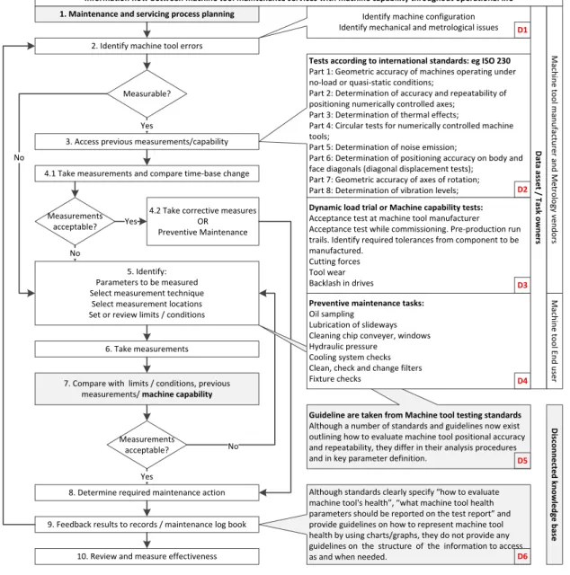
Each machine tool described above undergoes different testing phases throughout its life cycle, starting from manufacture testing phase to in-operational overhaul/maintenance testing phase. Different testing phases are illustrated Figure 1 (D1-D4 Task owners) with machine tool operational life span. Although, a flow chart provided in ISO 17359
8 specify steps in executing maintenance and service process plans for machine tools, additional details on what
information is required in identifying and comparing failure modes of the machine tools are added in Figure 1 (Step 3, D2-D4). Usually, machine tools are tested according to established machine tool testing standards such as ISO 230 series. These tests are performed by machine tool manufacturer during machine tool building phase and then by metrology service providers during use phase. The information generated through these tests usually remains with machine tool manufacturer or with metrology vendor in a proprietary format. Only abstract level of information, in the form of standard reports and control charts are delivered to end user which provide an indication of machine tool accuracy. It is only after control charts are manually interpreted, that machine tool maintenance decisions can be made. During use phase, the task of measuring and comparing machine tool errors requires previous measurement data in order to estimate extent of failure and plan corrective measures. Although extensive amount of literature and commercial metrology tools are available to evaluate machine tool errors, considerably less attention has been given on how this time-base information can be re-used for avoiding invasive machine tool testing procedure which demands significant machine down-time.
2.3.Maintenance process planning strategies and challenges
Machine tool testing is one of many tasks need to carried out as a part of maintenance process. As described before, machine tool testing is carried out from machine tool assembly phase throughout its operational life span when required. Several process planning for machine tool maintenance and services such as Collaborative Maintenance
Planning System (CoMPS)9, Industrial Product Service Systems (iPSS) 10, Cloud-based Maintenance 11 can be seen in
the literature; most proposing a software service to schedule maintenance tasks. However, there is a need to address how this information can be standardized and stored so that it can be readily compared when generated through different metrology resources and different metrology vendors.
Apart from standards test specified in Figure 1 (D2), other operational tests under dynamic loading may require for custom made, newly developed machine tools (eg. dedicated mass production machines). As these machine tools are designed for manufacturing unique products, machine capability study is usually carried out before commissioning. Whereas other general purpose and flexible machine tools are tested for machine capability during use phase, as products required to be manufacture on these machine tools changes during its use. This situation has resulted in
174 Parag Vichare et al. / Procedia Manufacturing 16 (2018) 171–178
4 Author name / Procedia Manufacturing 00 (2018) 000–000
multiple instances of machine tool testing data archived by machine tool builders, metrology vendors and end users. Thus, standardize systems to store and analyse machine tool testing data would be beneficial to end users. This will primarily benefit discrete, high value manufacturing businesses (small and medium scale industries) as well as large manufacturing industries (such as Aerospace and automotive manufacturing) to map component tolerances with
machine capabilities without investing cost and time in capability studies 1. STEP based methodology called MRCP
is proposed by Vichare et al 4, providing a mechanism to store and combine multi-metrology-resource generated
machine tool measurement data. This will be utilized in this paper to schedule maintenance tasks. 1. Maintenance and servicing process planning
2. Identify machine tool errors
5. Identify: Parameters to be measured Select measurement technique
Select measurement locations Set or review limits / conditions
6. Take measurements 7. Compare with limits / conditions, previous
measurements/ machine capability Measurable?
4.2 Take corrective measures OR
Preventive Maintenance
Measurements acceptable?
8. Determine required maintenance action 9. Feedback results to records / maintenance log book No
Yes
Yes
No
10. Review and measure effectiveness 3. Access previous measurements/capability 4.1 Take measurements and compare time-base change
Measurements acceptable? Yes
No
Identify machine configuration Identify mechanical and metrological issues Tests according to international standards: eg ISO 230 Part 1: Geometric accuracy of machines operating under no-load or quasi-static conditions;
Part 2: Determination of accuracy and repeatability of positioning numerically controlled axes;
Part 3: Determination of thermal effects;
Part 4: Circular tests for numerically controlled machine tools;
Part 5: Determination of noise emission;
Part 6: Determination of positioning accuracy on body and face diagonals (diagonal displacement tests);
Part 7: Geometric accuracy of axes of rotation; Part 8: Determination of vibration levels;
Guideline are taken from Machine tool testing standards Although a number of standards and guidelines now exist outlining how to evaluate machine tool positional accuracy and repeatability, they differ in their analysis procedures and in key parameter definition.
Although standards clearly specify “how to evaluate machine tool's health”, “what machine tool health parameters should be reported on the test report” and provide guidelines on how to represent machine tool health by using charts/graphs, they do not provide any guidelines on the structure of the information to access as and when needed.
Dynamic load trial or Machine capability tests: Acceptance test at machine tool manufacturer Acceptance test while commissioning. Pre-production run trails. Identify required tolerances from component to be manufactured.
Cutting forces Tool wear Backlash in drives
Preventive maintenance tasks: Oil sampling
Lubrication of slideways Cleaning chip conveyer, windows Hydraulic pressure
Cooling system checks Clean, check and change filters Fixture checks M ac hin e t oo l m an ufa ctu re r a nd M etr olo gy ve nd ors M ac hin e t oo l E nd u se r Dis co nn ec te d k no w led ge b as e Da ta as se t / Ta sk o w ne rs
Information flow between machine tool maintenance services with machine capability throughout operational life
D1 D2 D3 D4 D5 D6 Fig. 1. Information required for executing machine tool maintenance services and estimating machine capability.
3.Machine tool health/capability profiles for achieving through-life maintenance information
Although machine tool testing standards clearly specify “how to evaluate machine tool’s health”, “what machine
tool health parameters should be reported on the test report” and provide guidelines on how to represent machine tool
health by using charts/graphs, they do not provide any guidelines on the structure of the information to construct these graphs or charts. Thus, technology providers have adapted proprietary information modelling methodologies, resulting in non-interoperable machine tool health information in a variety of formats. Thus, MRCP extends current scope of
ISO 14649 part 201 7 and includes machine tool testing data generated through multiple metrology resources.
3.1.Assessment of component tolerances for product manufacture
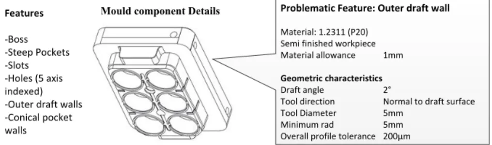
Figure 2 presents a case scenario, where 5 axis machine has been tested using a vendor specified cutting test. The same machine has been tested for its positioning accuracy using standard ball-bar equipment throughout its use phase. This machine tool was tested for its capability to produce injection mould cavity for producing a culture well plates for growing bone cells using nano-kicking bio-reactor. This scenario presents typical discrete part manufacturing case, where general purpose machine tool will be utilized for machining a new product. The case assessment for machine tool capability has been conducted through flowchart provided in Figure 1.
Mould component Details
Features -Boss -Steep Pockets -Slots -Holes (5 axis indexed) -Outer draft walls -Conical pocket walls
Problematic Feature: Outer draft wall
Material: 1.2311 (P20) Semi finished workpiece Material allowance 1mm
Geometric characteristics
Draft angle 2°
Tool direction Normal to draft surface Tool Diameter 5mm
Minimum rad 5mm Overall profile tolerance 200µm
Fig. 2. Mould-base component to be manufactured on Hurco VM10ui. 3.2.Assessment of machine tool health using time-base testing data
The machine tool configuration is known to end user in terms of axis configuration and travel limits. However, positioning accuracy data is listed in the form of test reports. As this machine was commissioned 7 years ago, corresponding test reports (or maintenance logs) were not easily accessible. Recent measurement report through ball-bar test was available indicates positioning accuracy of the machine. This ball-ball-bar test conducted on the machine was
a part of investigative tests to establish a methodology proposed by Flynn et al 12 to identify position independent
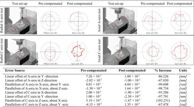
kinematic errors within the rotary axes using a single setup. Table 1 provides ball-bar setups and corresponding test graphs generated through these tests. It should be noted that machine was tested as a part of machine capability studies in uncompensated state. Corresponding ballbar results (as shown in uncompensated graphs in Table 1) were available when this machine was considered for producing mould components. According to these graphs maximum value for Radial A axis error is 350µm, which was unacceptable to achieve required profile tolerance of 200µm.
Initial assessment using ballbar test results invalidates use of this machine as draft walls need to be machined with a cutting tool normal to draft surface. A axis angular positioning accuracy determines profile tolerance specified on draft walls. Other features such as cooling holes does not hold tight positioning tolerances, although required A and C axis for tool positioning. Measurement data (A and C axis positions and corresponding axis deviation) of ballbar test was not available in the report as this data was captured within ballbar software. Thus, opportunity to investigate this data for toolpath compensation was lost during the process planning stage and component manufacture was subcontracted.
Retrospectively, uncompensated test data was analysed using Flynn et al 12 methodology. The four testing toolpaths
were generated using a sequence of linear interpolations, connecting sampled locations along the toolpath motion (approximately 5400 points for each toolpath). Using these toolpaths, the position and tilt errors of each rotary axis were identified, and are presented in Table 1. Corresponding compensated graphs are showing noteworthy improvement in angular positioning error. It can be seen in the Table 1 that in six errors, the error values have undergone a reduction of circa 85 - 99%. This marks a significant improvement, demonstrating the value of the
1766 Author name / Procedia Manufacturing 00 (2018) 000Parag Vichare et al. / Procedia Manufacturing 16 (2018) 171–178–000
information gathered using the proposed method. This indicates worth of considering time based measurement data in the process planning stage, absence of which can lead to underutilization of manufacturing resources or machine down time in order to gather required maintenance/measurement test data.
Table 1: Pre and post-compensation ballbar setups, corresponding plots from each of the four tests undertaken on the HURCO VM10Ui machine tool and Pre and post-compensation error source values.
R ad ia lA -a xi st es t A xi al A -a xi st es t R ad ia lC -a xi st es t A xi al C -a xi st es t
Test set-up Pre-compensated Post-compensated Test set-up Pre-compensated Post-compensated
Error Source Pre-compensated Post-compensated % Increase Units
Linear offset of A-axis in Y -direction 7.26 × 10⁻² 1.00 × 10⁻² -86.226 [mm] Linear offset of A-axis in Z-direction -2.02 × 10⁻² -1.00 × 10⁻² -47.030 [mm] Parallelism of A-axis to X-axis, about Y -axis 0.01 × 10⁻¹ 4.04 × 10⁻² -99.608 [rad] Parallelism of A-axis to X-axis, about Z-axis -1.30 × 10⁻⁴ 1.64 × 10⁻⁶ -98.734 [rad] Linear offset of C-axis in X-direction 2.00 × 10⁻² -1.90 × 10⁻³ -93.286 [mm] Linear offset of C-axis in Y -direction 1.00 × 10⁻¹ -2.30 × 10⁻³ -97.791 [mm] Parallelism of C-axis to Z-axis, about X-axis 5.19 × 10⁻⁶ -1.47 × 10⁻⁵ (183.231) [rad] Parallelism of C-axis to Z-axis, about Y -axis -4.15 × 10⁻⁵ 1.35 × 10⁻⁵ -67.478 [rad]
4.Measurement data consolidation using MRCP
The need of embedding dimensional inspection data with product data has been realized through IS0 103030 AP 219, which provides application protocol for exchanging information resulting dimensional inspection of solid parts,
as well as analyzing and archiving inspection results 13. Corresponding advantages and implementation frameworks
such as Quality Information Framework (QIF) 14 and Resource Independent Measurement Specifications (REIMS) 15
can be found in the literature. Similarly, a need of embedding metrology measurement data with machine tool model
has been recognized by Vichare et al 4, resulting STEP-NC compliant model called Manufacturing Resource
Capability profile (MRCP) for consolidating machine tool configuration (CAD geometry, kinematic information, technology identifiers) and health information (metrology data).
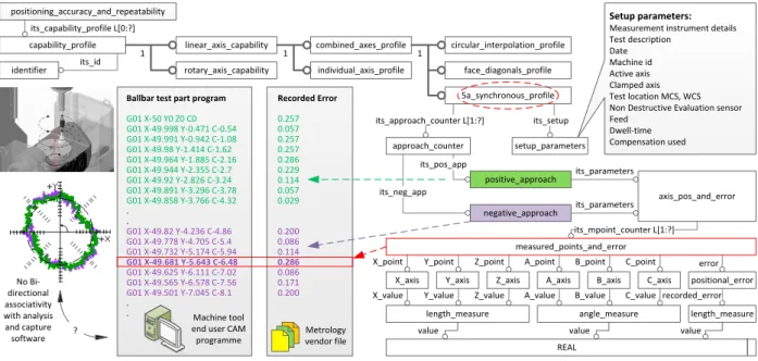
Figure 3 shows an extract of typical tool path executed on the machine tool for measuring axis errors using ball bar tests as shown in Table 1. Although test programme (G and M codes) can be generated using accompanying software
for standard ball bar tests (eg ISO 230 part 4: circular tests for numerically controlled machine tools 16.), customize 5
axis synchronous tests as conducted in this paper require an additional tool path generation application. These tests
can provide ISO 10791 part 6 17 complaint contouring accuracy of 4 and 5 axis machines by interpolating set of linear
axes and rotary axes simultaneously. It has been shown through the case study in Section 3 that this test measurement data, if available, can provide opportunity for compensation or further analysis to plan maintenance tasks or to perform capability analysis. Currently, ballbar test part programme (G and M codes) information remains with machine tool end user, whereas captured recorded error information remains with metrology vendor in a software specific format. An estimation of time required to gather this information by metrology expert can be in the range of few hours to several days, depending upon correctness, completeness and availability of the required information.
Figure 3 provides required information constructs to combine ballbar test part programme and recorded error
tool verification test results can be logged in the form of capability profiles. A specific capability profile can be attributed to machine tool testing standard and it can be classified as individual axis profile or combined axis profile.
For example, combined axis profile can be tested according to ISO 230 part 4 16 for circular interpolation using two
linear axis or it can be tested according to ISO 230 part 6 for volumetric performance using three linear axis. A case study presented in this paper involves 5 axis simultaneous interpolation using two linear axis and one rotary axis using ballbar. According to ISO 10791, each test is required to be performed in forward and reverse directions.
Corresponding entities “positive_approach” and “negative_approach” provide directional sense of approach with a
measurement point counter for the generated test programme. Each line of the generated programme can be tracked
with entity “measured_point_and_error”. This entity captures location of each axis under test and corresponding error as shown in Figure 3. capability_profile positioning_accuracy_and_repeatability its_capability_profile L[0:?] linear_axis_capability rotary_axis_capability individual_axis_profile combined_axes_profile face_diagonals_profile circular_interpolation_profile 1 1 1 its_id identifier
Ballbar test part program Recorded Error
G01 X-50 Y0 Z0 C0 0.257 G01 X-49.998 Y-0.471 C-0.54 0.057 G01 X-49.991 Y-0.942 C-1.08 0.257 G01 X-49.98 Y-1.414 C-1.62 0.257 G01 X-49.964 Y-1.885 C-2.16 0.286 G01 X-49.944 Y-2.355 C-2.7 0.229 G01 X-49.92 Y-2.826 C-3.24 0.114 G01 X-49.891 Y-3.296 C-3.78 0.057 G01 X-49.858 Y-3.766 C-4.32 0.029 . . G01 X-49.82 Y-4.236 C-4.86 0.200 G01 X-49.778 Y-4.705 C-5.4 0.086 G01 X-49.732 Y-5.174 C-5.94 0.114 G01 X-49.681 Y-5.643 C-6.48 0.286 G01 X-49.625 Y-6.111 C-7.02 0.086 G01 X-49.565 Y-6.578 C-7.56 0.171 G01 X-49.501 Y-7.045 C-8.1 0.200 . . 5a_synchronous_profile axis_pos_and_error its_approach_counter L[1:?] approach_counter negative_approach positive_approach positional_error its_parameters its_parameters length_measure its_pos_app its_neg_app its_setup setup_parameters
X_axis Y_axis Z_axis A_axis B_axis C_axis measured_points_and_error
its_mpoint_counter L[1:?] X_point Y_point Z_point A_point B_point C_point error
length_measure angle_measure
REAL
value value value
X_value Y_value Z_value A_value B_value C_value recorded_error
Setup parameters:
Measurement instrument details Test description Date Machine id Active axis Clamped axis Test location MCS, WCS Non Destructive Evaluation sensor Feed Dwell-time Compensation used No Bi-directional associativity with analysis and capture software ? Machine tool end user CAM
programme vendor fileMetrology
Fig. 3. Ballbar test tool path coordinates, recorded error and corresponding EXPRESS-G data model to capture measurement data.
Apart from axis location and recorded error, test setup information is equally important as it holds information regarding test location on the machine, corresponding work coordinate system (WCS), feed, data capture frequency,
compensation status etc. Corresponding information can be captured using MRCP’s entity “setup_parameters”; the
content of which is guided through relevant machine tool testing standards. It has been seen through machine testing experience that this information can be verified through test reports, thus correctness and completeness of the capability profile can be confirmed. The objective of this data model is to create multiple instances of capability profile as machine tool is tested throughout its life, from manufacture to service phase.
5.Discussion and future work
Integrated maintenance covers through-life engineering services for a machine tool, which involves various stakeholders such as machine tool manufacturer, machine tool end users and metrology service providers. This paper presents a practical case scenario of discrete part manufacturing, which requires machine tool assessment before manufacturing decisions are made. Corresponding information, which forms a basis for assessment is a part of through-life maintenance services. This information remains distributed among stakeholders, which could be difficult to access when needed, resulting product data equivalent standards for representing machine tool data. MRCP particularly emphasizes representing wide spectrum of machine tools and associated auxiliary resources for various manufacturing applications. This representation includes geometric model of the machine tool, kinematic structure,
1788 Author name / Procedia Manufacturing 00 (2018) 000Parag Vichare et al. / Procedia Manufacturing 16 (2018) 171–178–000
technology descriptors and health of the machine tool. Challenges in assimilating this information has been addressed
18 while discussing reusability of this information. It has been highlighted that acceptance and validity of standards
for representing machine tool data can only be appraised if they can represent advancement in technology, in this case novel methods of testing 5 axis machine tools.
5 axis machine tool test presented in this paper uses a ballbar equipment. This test can be performed on any 5 axis milling, turing or turn/mill centers, which generates an instance of machine tool verification. Similar test can be performed with other metrology resources such as R-Test. A data model presented in this paper provides a metrology resource independent methodology to capture machine tool verification state by extending current scope of MRCP. This verification state can be consider as a capability profile, which can integrate test programme and corresponding recorded results for machine tool assessment. This information can be integrated in through-life maintenance services, which can be access without any measurement data loss. Corresponding information package can provide represent concurrent state of the machine tool, providing a platform to configure digital twin of the manufacturing resource.
Future work will be focused on developing a prototype application for STEP-NC compliant information storage and data connectivity capabilities among the stakeholders involved in the manufacturing supply chain and in the entire lifecycle of the machine tool, so that machine manufacturers and end-users can access / exchange / re-use this information in a coherent and effective way while using their own manufacturing decision making applications. Decision making workbenches will be configured as a part of this future work. These workbenches are dedicated tools for different stakeholders for assisting them in making informed decisions based on the actual capability of the available manufacturing resources. The required information for making these decisions will be delivered through MRCPs.
References
1. Knapp W. Measurement uncertainty and machine tool testing. Cirp Ann-Manuf Techn. 2002; 51: 459-62.
2. Perkins C, Longstaff AP, Fletcher S and Willoughby P. Practical implementation of machine tool metrology and maintenance management systems. J Phys Conf Ser. 2012; 364.
3. Newman ST and Nassehi A. Machine tool capability profile for intelligent process planning. Cirp Ann-Manuf Techn. 2009; 58: 421-4. 4. Vichare P, Nassehi A, Thompson J, Newman ST, Wood F and Kumar S. Machine tool capability profiles for representing machine tool
health. Robot Cim-Int Manuf. 2015; 34: 70-8.
5. Moriwaki T. Multi-functional machine tool. Cirp Ann-Manuf Techn. 2008; 57: 736-49.
6. Nassehi A and Vichare P. A STEP-NC Compliant Methodology for Modelling Manufacturing Resources. Springer Ser Adv Man. 2009: 261-81.
7. ISO 14649-201. Industrial automation systems and integration - Physical device control, Data model for computerized numerical controllers, Part 201: Machine tool data for cutting processes. 2011.
8. ISO 17359. Condition monitoring and diagnostics of machines -- General guidelines. 2011.
9. Wan S, Gao J, Li DB, Tong YF and He F. Web-based process planning for machine tool maintenance and services. Proceedings of the 4th International Conference on through-Life Engineering Services. 2015; 38: 165-70.
10. Zhu Q, Jiang P, Huang G and Qu T. Implementing an industrial product-service system for CNC machine tool. Int J Adv Manuf Tech. 2011; 52: 1133-47.
11. Mourtzis D, Vlachou E, Milas N and Xanthopoulos N. A cloud-based approach for maintenance of machine tools and equipment based on shop-floor monitoring. Research and Innovation in Manufacturing: Key Enabling Technologies for the Factories of the Future - Proceedings of the 48th Cirp Conference on Manufacturing Systems. 2016; 41: 655-60.
12. Flynn JM, Shokrani A, Vichare P, Dhokia V and Newman ST. A new methodology for identifying location errors in 5-axis machine tools using a single ballbar set-up. The International Journal of Advanced Manufacturing Technology. 2016.
13. Zhao Y, Xu X, Kramer T, Proctor F and Horst J. Dimensional metrology interoperability and standardization in manufacturing systems.
Computer Standards & Interfaces. 2011; 33: 541-55.
14. Zhao YF, Horst JA, Kramer TR, Rippey W and Brown RJ. Quality Information Framework – Integrating Metrology Processes. IFAC Proceedings Volumes. 2012; 45: 1301-8.
15. Mahmoud H, Dhokia V and Nassehi A. STEP-based Conceptual Framework for Measurement Planning Integration. Procedia CIRP. 2016; 43: 315-20.
16. ISO 230 - 4. Test code for machine tools -- Part 4: Circular tests for numerically controlled machine tools. 2005. 17. ISO 10791 - 6. Test conditions for machining centres -- Part 6: Accuracy of speeds and interpolations. 2014.
18. Vichare P, Zhang XZ, Dhokia V, Cheung WM, Xiao WL and Zheng LY. Computer numerical control machine tool information reusability within virtual machining systems. P I Mech Eng B-J Eng. 2018; 232: 593-604.