Institute of Parallel and Distributed Systems University of Stuttgart
Universitätsstraße 38 D–70569 Stuttgart
Masterarbeit Nr. 88
Local Data Plane Event Handling in
Software-defined Networking
Matthias Fetzer
Course of Study: Softwaretechnik
Examiner: Prof. Dr. rer. nat. Dr. h. c. Kurt Rothermel Supervisor: M. Sc. Thomas Kohler
Commenced: October 15, 2015 Completed: April 15, 2016
Abstract
Software-defined networking is a rising technology for handling traffic in large networks. To ensure a high flexibility, software-defined networking separates the control plane from the data plane. The data plane forwards packets while the control plane defines the forwarding rules. In case packets or events need to be processed in a way that is not covered by these rules, the packets or events have to be forwarded to the control plane. This imposes latency to the processing of network traffic and events.
This master’s thesis proposes a concept for generic handling of local events in software-defined networks, using local data plane applications directly on the switch devices. During this thesis, a concept for local data plane event handling is developed and implementation details are discussed. The evaluation shows that processing of events directly on the data plane improves network performance and saves resources on the switch devices.
Kurzfassung
Software-defined Networking ist eine aufkommende Technologie zur Verarbeitung von Netzwerkverkehr in großen Netzwerken. Um eine höhere Flexibilität zu ermöglichen, sieht Software-defined Networking eine Trennung der Kontroll- und der Weiterleitungs-schicht vor. Die WeiterleitungsWeiterleitungs-schicht übernimmt das Verteilen von Paketen während die Kontrollschicht definiert, mit welchen Regeln dies zu erfolgen hat. Sofern man Pakete oder Ereignisse verarbeiten möchte, welche nicht mit diesen Regeln ausgedrückt werden können, müssen diese Pakete und Ereignisse an die Kontrollschicht weitergeleitet werden. Durch Latenzen in Netzwerken wird jedoch die benötigte Verarbeitungszeit der Ereignisse und Pakete erhöht.
In dieser Masterarbeit wird ein Konzept zur lokalen Behandlung von Ereignissen in der Weiterleitungsschicht beschrieben. Diese lokalen Ereignisse werden mittels An-wendungen auf Netzwerkswitches behandelt. Weiterhin wird auf die Details der Im-plementierung eingegangen. Die Evaluation zeigt, dass das lokale Verarbeiten von Ereignissen die Performanz erhöht und zusätzlich die Ressourcen auf den Netzwerk-switches schont.
Contents
1 Introduction 9 2 Foundations 11 2.1 Software-defined Networking . . . 11 2.2 OpenFlow . . . 15 2.3 Open vSwitch . . . 20 3 Related Work 23 4 Problem Statement and System Model 25 4.1 Problem Statement . . . 254.2 System Model . . . 26
5 Concept 29 5.1 Generalization of Data Plane Actions and Events . . . 29
5.2 Local Data Plane Applications . . . 31
5.3 Local Data Plane Event Processing . . . 35
5.4 Application Controller . . . 40
6 Implementation 43 6.1 Applications . . . 43
6.2 Application Repository . . . 44
6.3 Application Storage . . . 45
6.4 Ingress Packet Event Processing . . . 47
6.5 Generic Event Processing . . . 48
6.6 Application Controller . . . 49
6.7 Implementation of Use Cases . . . 50
7 Evaluation 57 7.1 Testbed Setup . . . 57
7.2 In-switch Benchmarks . . . 58
7.3 End Host Benchmarks . . . 62
7.4 Scalability Benchmark . . . 74
8 Conclusion and Future Work 79
A Implementation 81
List of Figures
2.1 Traditional and SDN architecture. . . 12
2.2 SDN system architecture . . . 14
2.3 Components of an OpenFlow switch. . . 16
2.4 OpenFlow switch to controller communication. . . 19
2.5 Open vSwitch flow tables . . . 21
2.6 Open vSwitch packet processing . . . 22
4.1 Components in the system model . . . 28
5.1 Overview of the in-switch concept . . . 32
5.2 Local data storage for application switch . . . 34
5.3 Distributed data storage for application switch . . . 35
5.4 OpenFlow application switch with application table . . . 37
5.5 OpenFlow application switch generic event processing. . . 38
5.6 OpenFlow application switch packet processing . . . 39
5.7 Communication between application switch and controller. . . 41
6.1 Activity diagram of the port knocking implementation . . . 52
6.2 Activity diagram of the multicast implementation . . . 54
6.3 Activity diagram of the simple switch implementation . . . 55
6.4 Activity diagram of the fast failover implementation . . . 56
7.1 Box plot of flow installation times. . . 59
7.2 Evaluational results of the CPU measurement. . . 61
7.3 Evaluational setup for port knocking . . . 64
7.4 Evaluational results for port knocking in LANs . . . 65
7.5 Evaluational results for port knocking in WANs . . . 66
7.6 Evaluational setup for multicasting . . . 67
7.7 Evaluational results for multicasting in LAN . . . 68
7.8 Evaluational results for multicasting in WAN . . . 69
7.9 Evaluational setup for the simple switch use case. . . 70
7.10 Evaluational results for simple switching. . . 72
7.11 Evaluational setup for fast failover . . . 73
7.13 Evaluational setup for multicasting with multiple clients. . . 76
7.14 Evaluational results for scaling the multicasting application. . . 77
List of Tables
2.1 Numbers of OpenFlow header fields and actions . . . 162.2 OpenFlow v1.0 match fields. . . 17
2.3 OpenFlow v1.0 actions . . . 17
5.1 Example use cases for local data plane event processing. . . 30
List of Listings
6.1 Generic application function signature. . . 446.2 Application repository function signatures. . . 45
6.3 Application data storage, application_db.h . . . 45
6.4 Application data storage prefix for local databases. . . 46
6.5 OpenFlow vendor id, openflow-common.h . . . 48
6.6 OpenFlow experimenter action struct, ofp-actions.c . . . 48
6.7 Handling of port change events, ofproto.c . . . 49
6.8 Implemented OpenFlow experimenter messages, ofp-msgs.h . . . 50
A.1 OpenFlow experimenter action struct, ofp-actions.h . . . 81
A.2 Decoding of raw experimenter message, ofp-actions.c . . . 81
1 Introduction
The internet has a massively growing number of users and connected devices. More and more users gain access to the internet, not only using traditional computers or laptops, but also via smartphones and tablet computers. But not only the personal usage of the internet is rising. With the advent of the internet of things and the internet of services the internet becomes even more crucial to business success.
This shift towards ubiquitous computing highly increases the level of mobility for internet devices. This mobility requires the underlying network to react fast to changing network topologies and changing network load. As traditional networks were not intended to support mobility to that degree, the pressure on organizations to be more agile than it is possible with traditional networking approaches increases.
Traditionally, most network functionality is implemented in dedicated hardware appli-ances, such as switches, routers or firewalls. These appliances unify the control and the data plane on a single device. While the data plane is used for the actual forwarding of traffic in the network, the control plane is used for defining the forwarding rules in the data plane. For example the forwarding of packets in a hardware switch is implemented in anapplication specific integrated circuit(ASIC) [Cit14] while the control plane is using a general purpose CPU. Implementing forwarding logic in ASCIs enables forwarding to be very fast, while using a CPU enables the switches to execute more sophisticated logic. On the other hand, the switches are limited in functionality by the ASIC.
Software-defined networking tries to overcome these limitations by shifting networking logic from the hardware-centric architectures towards a more distributed and less coupled software-centric approach. This software-centric approach can be described as a global controlling instance that configures the ASICs on the switches.
One of the most used software-defined networking standards is OpenFlow. OpenFlow specifies the communication between the global controlling instance and the switching ASICs. While OpenFlow addresses most parts of the upcoming challenges, such as support for high mobility, it in itself is a closed system. Reacting to packets can only be done by a predefined set of actions, and packet recognition is limited to a predefined set of header fields.
1 Introduction
These limitations can be overcome by the global controller. Data packets need to be sent to the controller in order to apply custom logic. This adds latency to the processing of data packets as they need to be transmitted to the controller. This latency can be up to a few milliseconds in local area networks or up to tens of milliseconds in wide area networks.
This thesis proposes an approach for stateful data plane event processing - that is the processing of events that do not need a controller to be handled properly.
This thesis is therefore structured as follows: Chapter 2 discusses the foundations for this thesis, Chapter 3 gives an overview of related approaches and Chapter 4 defines the underlying system model and the problem statement. The actual concept is presented in Chapter 5 and the implementation details are discussed in Chapter 6. The prototype is evaluated in Chapter 7. Chapter 8 summarizes the findings of this thesis and gives an overview of further required research.
2 Foundations
Before going into the development of a concept to locally handle events on the data plane, this chapter introduces its foundations. First, software-defined networking in general is presented. Then OpenFlow, as a software-defined networking standard, is discussed. In the last section Open vSwitch, as an implementation of the OpenFlow standard, is examined.
2.1 Software-defined Networking
Software-defined networking has been one of the most popular topics in networking during the last years. The goal of software-defined networking is to enable network engineers and administrators to dynamically and quickly react to changing business requirements, end-users and market needs [Ope12; Cit14].
As mentioned in the introduction, most network traditional network functionality is implemented in dedicated hardware appliances, such as switches and routers. Within these dedicated appliances, most of their functionality is implemented in hardware such as an application specific integrated circuit. The key characteristics of those proprietary appliances can be described as follows:
• The improvement of the appliance rests with the proprietary vendor.
• Each appliance is configured individually.
• Provisioning, change management and de-provisioning are very time consuming. Networking organizations are under pressure to be more agile than it is possible with the traditional approach [Cit14]. A further source of that pressure is the rising usage of server virtualization that requires virtual machines (VMs) to be moved around hosts dynamically in a matter of seconds or minutes [PPK+09; Cit14]. However if moving the VM crosses a Layer 3 boundary, reconfiguring traditional networks to support the new location of the VM can take much longer.
2 Foundations
Figure 2.1: Traditional architecture for control plane and data plane compared to seper-ated planes in SDN. In (a) the data plane and the control plan reside on the same physical device while in (b) those two planes are separated into two logical partitions which typically run in distinct hardware
In contrary to the traditional architecture of network components, software-defined networking proposes an architecture that separates the control plane from the data plane as depicted in Figure 2.1. Those separate planes can be described as follows:
• Data plane: The data plane (or forwarding plane) forwards network packets to other switches or end hosts by using fixed rule sets. The rules in the data plane are installed by the control plane.
• Control plane: The control plane is responsible for higher level protocols. The control plane decides which set of rules are installed on the data plane.
The rules on the data plane can either be installed proactively or reactively. When proactively installing rules on the data plane, rules that match future packets are installed. When installing rules reactively, rules are installed as a direct reaction to received packets.
As implied in Figure 2.1 (b) software-defined networking splits the control plane from the data plane and moves the control plane into an independent entity called the
2.1 Software-defined Networking
• Directly programmable: Network control is directly programmable because it is decoupled from forwarding functions.
• Agile: Abstracting control from forwarding lets administrators dynamically adjust network-wide traffic flow to meet changing needs.
• Centrally managed: Network intelligence is (logically) centralized in software-based SDN controllers that maintain a global view of the network, which appears to applications and policy engines as a single, logical switch.
• Programmatically configured: SDN lets network managers configure, manage, secure, and optimize network resources very quickly via dynamic, automated SDN programs, which they can write themselves because the programs do not depend on proprietary software.
• Open standards-based and vendor-neutral: When implemented through open standards, SDN simplifies network design and operation because instructions are provided by SDN controllers instead of multiple, vendor-specific devices and protocols.
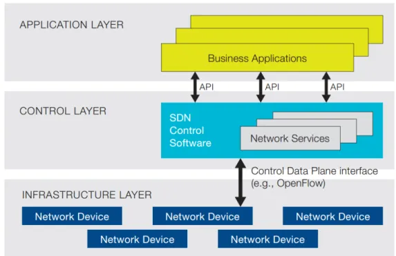
The architecture as envisioned by the ONF can be seen in Figure 2.2. This architecture involves the following key components:
• Business Applications: Applications consumable by the end user.
• Northbound API: The API between the business applications and the SDN control software. There is currently no standardized northbound API [Cit14].
• SDN Control Software: The traditional control plane in a separated and logically centralized manner. This layer includes network services such as security, firewalls or distributed denial-of-service (DDoS) protection. This is often referred to as the
SDN Controller.
• Southbound API: The southbound API enables communication between the con-trol plane and the infrastructure layer. There are some standardized protocols for southbound communications such as OpenFlow, XMPP[Jun13] or the Network Configuration Protocol[eEnn11].
A downside introduced by this architecture are increased latencies. If data plane packets are handled reactively, they are sent to the control plane. The control plane then decides how to handle the received packet. The instructions to handle the packet have to be pushed down to the data plane. Furthermore increasing load within a (logical) centralized control plane for a greater set of data plane elements may lead to scalability issues or might provide single points of failures.
2 Foundations
Figure 2.2: SDN System architecture as proposed by the ONF.
2.2 OpenFlow
2.2 OpenFlow
As mentioned in section 2.1 there are several protocols for the southbound API. This section covers the southbound protocol proposed by the Open Networking Foundation.
OpenFlow was the first standard communication interface between the control and forwarding layers of an SDN architecture [Ope12].
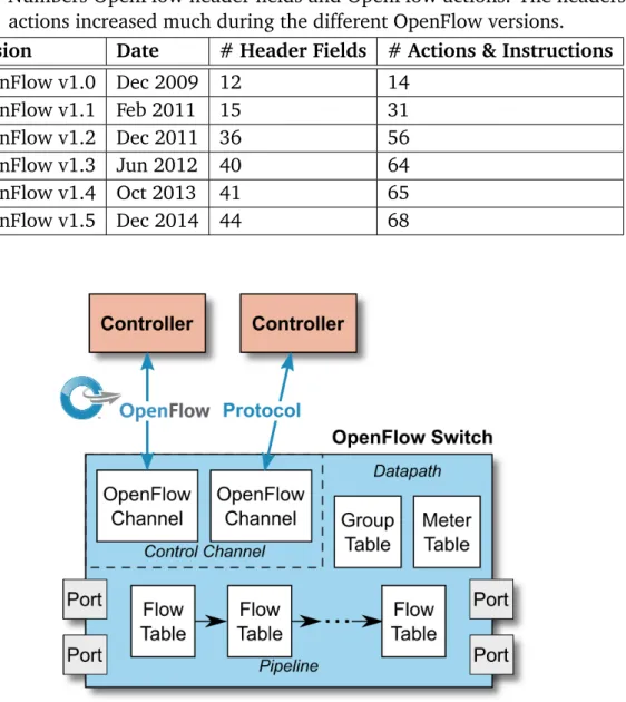
The OpenFlow standard [Pro13] defines the following components, as seen in Fig-ure 2.3:
• One or more flow tables and a group table: Those perform packet lookups and forwarding.
• One or more OpenFlow channels: Communication channels to communicate with the controllers.
The OpenFlow protocol enables the controller to add, update and delete flow table entries in the flow tables. This can be done reactively (after receiving packets from the switch) or proactively (by adding flow table entries that may be needed later). Each flow table consists of a set of flow entries.
2.2.1 OpenFlow Flow Entries
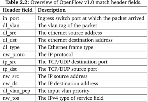
Flow entries are a set of rules and actions to be executed if a packet matches a rule. Ta-ble 2.2 shows the matchaTa-ble header fields for OpenFlow v1.0 as well as their description. The associated actions can either describe how the packets are forwarded, how they are modified or if they need to be forwarded to other flow tables. Table 2.3 exemplary shows available actions for OpenFlow v1.0. Since OpenFlow v1.0 many actions and match fields were added. A full and up to date list of fields and actions can be found in the OpenFlow Switch Specification v1.5.0 [Pro13]. Table 2.1 shows how the numbers of header fields and actions have increased from OpenFlow v1.0 to OpenFlow v1.5 [Kre15]. This shows that there is an increasing demand for new header fields and new actions. Match-action pairs consist of a match and an action set. They are in the form of <{ matches }, { actions }>. This means: If all matches match, all actions in the action set will be executed.
For example a match-action pair of <{ in_port=1 }, { output=2 }> will match any packet that was coming from the first switch port and will output this packet on the second switch port.
2 Foundations
A more sophisticated example would be the pair of<{ in_port=1, dl_type=0x0800 }, { set_dl_src=DE:AD:BE:EF:CA:FE ,output=2 }>. This will match any packet coming from the first switch port and being an IPv4 packet. It will rewrite the source MAC address and then output the modified packet on the second switch port.
Table 2.1:Numbers OpenFlow header fields and OpenFlow actions. The headers and actions increased much during the different OpenFlow versions.
Version Date # Header Fields # Actions & Instructions
OpenFlow v1.0 Dec 2009 12 14 OpenFlow v1.1 Feb 2011 15 31 OpenFlow v1.2 Dec 2011 36 56 OpenFlow v1.3 Jun 2012 40 64 OpenFlow v1.4 Oct 2013 41 65 OpenFlow v1.5 Dec 2014 44 68
Figure 2.3: Main components of an OpenFlow switch. The OpenFlow protocol defines the communication between the controllers and the OpenFlow Switch.
2.2 OpenFlow
Table 2.2: Overview of OpenFlow v1.0 match header fields.
Header field Description
in_port Ingress switch port at which the packet arrived dl_vlan The vlan tag of the packet
dl_src The ethernet source address dl_dst The ethernet destination address dl_type The Ethernet frame type
nw_proto The IP protocol
tp_src The TCP/UDP destination port tp_dst The TCP/DUP source port nw_src The IP source address nw_dst The IP destination address dl_vlan_pcp The input vlan priority nw_tos The IPv4 type of service field
Table 2.3:Overview of OpenFlow v1.0 actions.
Action Description
Output Output packet to a given port. SetVLANID Set a VLAN id.
SetVLANPCP Set VLAN PCP. StripVLAN Strip VLAN.
SetDLSrc Set data layer source address. SetDLDst Set data layer destination address. SetNWSrc Set network layer source address. SetNWDst Set network layer destination address. SetNWTos Set the network TOS.
SetTPSrc Set the transport layer source address. SetTPDst Set the transport layer destination address. Enqueue Map a flow to a existing queue.
2 Foundations
2.2.2 OpenFlow Packet Processing
Matching ingress packets starts at the first flow table. The first matching flow entry is used and the associated actions are executed. If there is no match in the flow table, the following scenarios are possible, depending on the switch configuration:
1. The packet may be forwarded to the controllers. 2. The packet may continue to the next flow table. 3. The packet may be dropped.
Forwarding packets to the controller was the default behaviour in OpenFlow v1.0 but the default has since been changed to dropping packets in more recent versions.
2.2.3 OpenFlow Communication
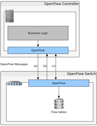
As seen in Figure 2.4 the communication between the switch and the controller in OpenFlow supports three kinds of messages types:
(a) Controller-to-Switch messages: These messages are initated by the controller and are used to directly manage or inspect the switch [Pro13].
(b) Asynchronous messages: These messages are sent from the switch and are used to notify the controller of events or the current switch state [Pro13].
(c) Symmetric messages: These messages are sent by either the switch or the con-troller [Pro13].
Important and often used controller initiated messages are:
• FlowMod: This message adds, removes or modifies flow table entries on the switch.
• PortMod: This message modifies the state of OpenFlow ports.
• PacketOut: This message is used to inject packets into the data plane.
Important messaged initiated by the switch are:
• FlowRemoved: This message is sent to the controller to notify that a flow entry from
the flow table has been removed.
• PortStatus: This message is sent to the switch asynchronously indicating the
2.2 OpenFlow
Upon receiving messages from the switch, the controller may execute any business logic and react to the received message. The controller then influences the switch by sending messages towards the switch. In many cases this will be FlowModor PacketOut
messages.
Figure 2.4: OpenFlow Communication: (a) Controller-to-switch message, (b) Asyn-chronous switch-to-controller message, (c) Symmetric bi-directional mes-sages.
2 Foundations
2.3 Open vSwitch
This section describes the architecture and implementation details of Open vSwitch. Open vSwitch is an open-source implementation of a distributed software switch for major VM hypervisor platforms [PPK+15]. Open vSwitch is designed for networking in virtual environments such as Xen, KVM and Docker.
2.3.1 Open vSwitch Architecture
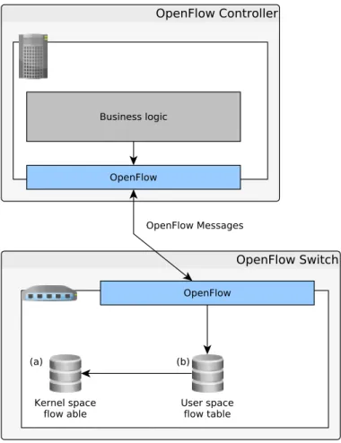
As a conceptual foundation the architecture of Open vSwitch is used, because it is widely used in production and considered stable. For performance reasons, but also for reasons of being accepted to upstream Linux, Open vSwitch uses a two layered table layout [PPK+15]. These two layers can bee seen in Figure 2.5 and can be described as follows:
• Kernel flow table: The kernel flow table contains less sophisticated flow table entries [PPK+15]. As those flow entries are of a more simple nature they can be processed faster and directly in the kernel. Furthermore the kernel flow table acts as a cache for flow table entries in the user space flow table. Less sophisticated flow entries from the user space table get cached in the kernel flow table. Those less sophisticated flow table entries do not contain wildcards or priorities and therefore match at most packets of a single transport connection [PPK+15]. This ensures that processing of packets that match a recently used flow entry will be done in the kernel.
• User space flow table: The user space flow table contains OpenFlow flow entries. If possible, these flow entries are propagated to the kernel flow table when they are needed. This table can hold more sophisticated flow entries than the kernel flow table and may hold more entries in general [PPK+15].
New OpenFlow rules are installed into the user space table. Hence the user space components are used for the actual OpenFlow communication. This two layered table layout enables Open vSwitch to be very fast for simple forwarding tasks using the kernel flow table but still be able to process more complex flow table entries using the user space flow table. As a downside this may reduce the performance for fast changing flow table entries as it is only periodically validated if existing flow table entries need to be changed.
2.3 Open vSwitch
Figure 2.5: Open vSwitch kernel space (a) and user space (b) flow tables. The kernel space flow table is populated using the user space table, while the user space table is populated using OpenFlow.
2.3.2 Open vSwitch Packet Processing
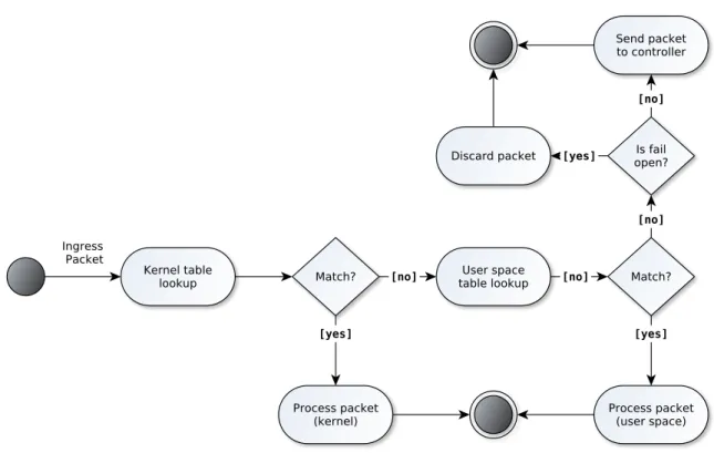
Combining the information from subsection 2.3.1 and subsection 2.2.3 the packet flow as shown in the activity diagram in Figure 2.6 can be concluded.
When an ingress packet arrives at the switch, the following steps are executed:
1. The packet headers are matched against those in the kernel flow table. If all headers match, the packet it is directly processed in the kernel module.
2. If there is no match in the kernel flow table, a lookup in the user space table is performed. If this lookup is successful, the packet is processed.
3. If the user space lookup did not yield any results and the switch is set to fail-open, then the packet is sent to the controller. Otherwise the packet is discarded.
2 Foundations
Figure 2.6:Open vSwitch packet processing, including both flow tables.
2.3.3 Open vSwitch Database Management Protocol
Open vSwitch uses a localOpen vSwitch Database Management Protocol server (ovsdb-server) [Pfa] to store and retrieve local data. The ovsdb-server is used to configure the switch and to retrieve information about the switch status. The saved information is persisted on disk and survives reboots.
3 Related Work
Recently there have been several approaches to overcome the limitations of fixed sets of OpenFlow matches and actions as well as the disadvantages that come with the latency from the switch to the controllers.
Bianchi et al. [BB14] proposed in their OpenState paper the use ofeXtended Finite State Machines(XFSM). They argue that programmers should be able to formally specify how states on the switch should be handled and this specification should be executed directly on the device without any controller interaction. According to Bianchi et al. the solution
must not violate the vendor-agnostic principles that had driven OpenFlow. Regarding the actions to be executed, they limit themselves to standard OpenFlow actions. Their main contribution is an abstraction to formally describe stateful processing of network flows directly on the switch device.
FAST, proposed by Moshref et al. in theirFlow-level State Transition as a New Switch Primitive for SDN paper [MBG+14], recommends a similar approach, using state ma-chines. They suggest flow-level state transitions as a new switch abstraction that allows the controller to program the state transitions proactively. The switches then run these dynamic actions based on their local information. Moshref et al. show that their FAST data plane is slightly slower than proactive but much faster than reactive processing of packets.
In contrast to the state machine approaches Mekky et al. [Mek14] suggest the use of more abstract local data plane applications. Their proposed applications are similar to the applications defined in this thesis. Furthermore they discuss where incoming packets should be handled by the applications. They argue that adding application actions into the flow tables would require these actions to be implemented in user space as well as in kernel space. In contrast, the concept developed in this thesis allows application specific actions inside the user space tables. This allows the combination of standard OpenFlow and application specific actions. Mekky et al. point out that further work has to be done on the dynamic adding of applications to the data plane. To address this issue, this thesis proposes a concept that includes the addition and removal of applications as well as a generic approach to the data storages used by these applications. They conclude that local processing of incoming packets increases performance, but might be not suitable if all packets need to be processed in user space.
3 Related Work
Focusing on the actual matching of packets, Bosshart et al. [BDI13] propose a high-level programming language P4 to program protocol-independent packet processors. Their three goals are:
1. Reconfigurability in the field: Programmers should be able to change the way switches process packets once they are deployed.
2. Protocol independence: Switches should not be tied to any specific network protocols.
3. Target independence: Programmers should be able to describe packet-processing functionality independently of the specification of the underlying hardware. Their solution should overcome the fixed set of matching fields (see section 2.2) and allow to dynamically add (or remove) new header fields for the needed match-action pairs. To achieve this, they compile their P4 programs into table dependency graphs and map these graphs to the target switches.
The works done by Bianchi et al. [BB14], Moshref et al. [MBG+14] and Mekky et al. [Mek14] focus on the event of incoming packets at the data plane. This thesis goes a step further and suggests a more generic way of handling events of any type. Although, in this thesis, the handling of incoming packets is still treated as a special case.
4 Problem Statement and System Model
After presenting the foundations for this thesis, this section discusses shortcomings with software-defined networks and how this thesis proposes a concept for solving these issues. Afterwards, the underlying system model is defined.
4.1 Problem Statement
Software-defined networking separates the data plane from the control plane. The decapsulation of these components enables to scale the control plane irrespective of the data plane. To achieve this, the communication between the data plane and the control plane has to be standardized. This limits the data plane to react with a predefined set of actions to a predefined set of rules.
For more sophisticated logic, packets have to be forwarded to the control plane. Then the control plane can decide on the processing of the received packet. As the control plane is logically centralized, global knowledge from the whole data plane can be used when processing packets.
This reactive approach adds latency to the processing of packets that cannot be processed with the predefined sets of rules and actions. The added latency depends on the latency between the data plane and the control plane, i.e. the latency between the switch and its controllers. Packets have to be forwarded to the control plane and the control plane has to forward instructions to the data plane. This imposed latency amplifies with increasing latency between the control and the data plane.
While networking logic that requires a global view to be handled, requires information to be sent to the controller, events that only require local knowledge might be handled locally on the switch.
This thesis analyzes event types that can be processed locally and suggests a way on how to handle them. A prototype of the local event processing is being implemented and evaluated against the approaches that involve a controller.
4 Problem Statement and System Model
In order to achieve this, the following research goals were defined:
• G1: Generalization of data plane events and data plane actions.
• G2: Design of a data plane event handling interface.
• G3: Design of a data storage.
• G4: Analysis & modification of an existing software switch.
• G5: Evaluation of prototypical implementation.
The goalsG1-G3 are discussed in chapter 5. Chapter 6 coversG4. G5is discussed in chapter 7.
4.2 System Model
This section describes the underlying system model for the developed concept of this thesis. First, the components and their cardinalities are defined. Afterwards, the failure model is described.
4.2.1 Components and Cardinalities
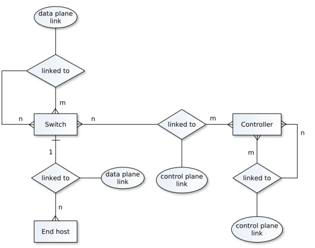
Figure 4.1 shows the network components and the relations between these network components. Network components are illustrated as square boxes while the links are depicted as diamonds. The link types are depicted as circles specifying the type of link. The cardinalities are denoted along the edges.
The components and their cardinalities are as follows:
• Controller: A controller is a OpenFlow SDN controller. There are any number of controllers in the network.
• Switch: A switch that supports the OpenFlow standard. There are any number of switches in the network.
• End Host: Any number of end hosts are in the network. Each end host is connected to exactly one switch using a physical link.
4.2 System Model
• Control plane links: The control plane links are links from switches to controllers and between controllers. This might be a direct physical link, but can also be a link using multiple physical links.
The relations between these components can be formally described as follows:
• Network := { Components } ×{ Links }
• Components := { Switches ∪Controllers∪End hosts }
• Links := { Linkdata ∪Linkcontrol}
• Linkdata := { linkd(c1, c2) | linkd(c1, c2) = true} • Linkcontrol := { linkc(c1, c2) | linkc(c1, c2) =true}
The values for linkd(c1, c2) are defined for end hosts and switches. The exact values are
defined as follows:
1. linkd(c1, c2) = true, if c1 or c2 are directly connected. Each host can only be
connected to one switch.
2. linkd(c1, c2) =f alse, if both c1 and c2 are end hosts. This means: End hosts might
not be directly connected to each other. The relation linkc(c1, c2) is defined as follows:
• linkc(c1, c2) =true, if c1 or c2 there exists a path in the network that enables c1 to
reach c2 and vice versa. One of both components needs to be a controller.
• linkc(c1, c2) = f alse, if both c1 and c2 are switches. Switches are not connected
via data plane links.
4.2.2 Failure Model
For the previously defined components and their channels the following failure model is assumed:
1. Controller and switch processes never crash.
2. Communication channels between the switches may drop or duplicate packages. 3. Communication channels between the controller and the switches have no failures.
4 Problem Statement and System Model
Figure 4.1:The components and their relations in the system model.
As this thesis focuses on events at the local data plane, the control plane is assumed to be working correctly at all times. For the same reason, the channels between control and data plane are assumed to have no failures. As the concept focuses on a higher abstraction level, it is assumed that the switch processes always behave correctly.
5 Concept
This section discusses the developed concept to handle data plane events locally. First, the event and action types are generalized and some motivating examples are given. Afterwards, local data plane applications are introduced and the event processing is explained. Lastly, the interaction between the controller and the switches is described.
5.1 Generalization of Data Plane Actions and Events
Prior to developing a concept on how to handle local data plane events, possible use cases were analyzed in order to classify events on the data plane and the possible actions when handling those events locally. The following section covers these events and actions.
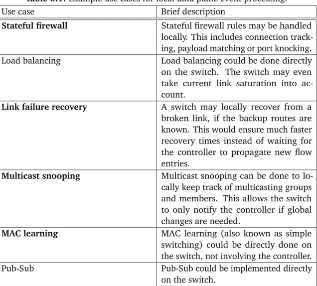
A selection of motivating example use cases for local data plane event processing can be found in Table 5.1. The bold use cases have been implemented in the prototype.
5.1.1 Data Plane Events
The data plane events found during the analysis of the motivating examples and other use cases, can be categorized as follows:
• Packet-In: The most basic event to react to would be the event of ingress packets at the switch. The switch itself might then parse the packet headers and react to them accordingly.
• State: The switch may handle state events locally. This might be from state machines or a more abstract form of state, such as local switch port failures.
• Local counters: The switch may monitor and handle events from local counters independently. This includes packet counters or the current buffers of the physical switch ports. Local processing logic can be applied to these counters which decide when to trigger local event processing.
5 Concept
• Payload: Matching of the payload of ingress packets may trigger local events. Those events then can be handled locally. This includes the introduction of new matching headers or naive string matching of packet payload.
Table 5.1: Example use cases for local data plane event processing.
Use case Brief description
Stateful firewall Stateful firewall rules may be handled locally. This includes connection track-ing, payload matching or port knocking. Load balancing Load balancing could be done directly on the switch. The switch may even take current link saturation into ac-count.
Link failure recovery A switch may locally recover from a broken link, if the backup routes are known. This would ensure much faster recovery times instead of waiting for the controller to propagate new flow entries.
Multicast snooping Multicast snooping can be done to lo-cally keep track of multicasting groups and members. This allows the switch to only notify the controller if global changes are needed.
MAC learning MAC learning (also known as simple
switching) could be directly done on the switch, not involving the controller. Pub-Sub Pub-Sub could be implemented directly
5.2 Local Data Plane Applications
5.1.2 Data Plane Actions
In addition to the existing OpenFlow actions, the following actions should be executable from inside the switch when handling the local events explained in subsection 5.1.1.
• State: Data plane actions should be able to locally change, add or remove local states. This can be state machines or more abstract form of data.
• Controller interaction: Data plane actions should be able to notify the controller of their current state or progress. Furthermore they should be able to request new information from the controller.
• Payload modification: When implementing the handling of packets that match a self defined packet format, it might be needed to be able to modify the payload of these packets. This can be compared to TCP port rewriting in standard OpenFlow actions but might also be used for more extensive modifications.
• Local counter rules: Local data plane actions should be able to create, read, remove or update rules that decide whether a local counter may trigger local event processing.
5.2 Local Data Plane Applications
To be able to process packets and events locally, the switch needs to be able to apply custom logic to local events. This concept introducesdata plane applicationson the data plane to existing OpenFlow switches. OpenFlow switches augmented with the ability to execute applications are introduced as OpenFlow application switches. This section describes the concept of local data plane applications
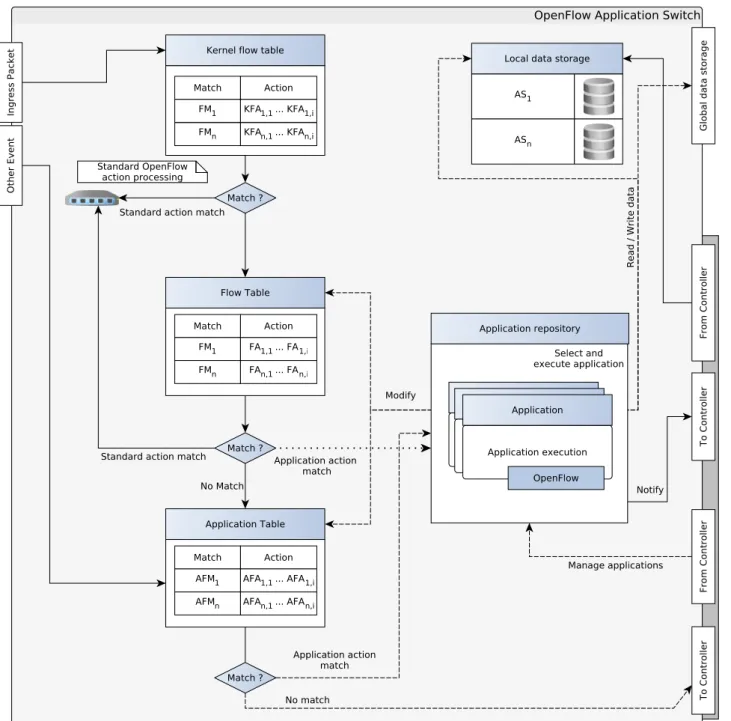
Figure 5.1 shows an overview of the conceptual elements inside the switch. The following sections describe the elements of these elements.
5 Concept
Figure 5.1: Overview of the in-switch concept. Events are denoted on the left border and interaction with the controller on the right. The kernel flow table holds flow matches (FM) and kernel flow actions (KFA). The flow table contains flow matches and flow actions (FA). The application table contains application flow matches (AFM) and application actions (AF). The applications get
5.2 Local Data Plane Applications
5.2.1 Applications
The introduced applications are a set of instructions that run locally on the switch and may be triggered from local data plane events occurring at the switch. Each application has a local associated data storage to be able to persist its state or save meta information for later processing. Each application has an unique identifier to be able to reference the application during the processing of local data plane events.
Applications are portable packages that can be installed, removed or modified using a SDN controller. Upon execution, applications may modify theflow tableor theapplication table. The application flow table defines when to execute which applications and is explained in more detail in section 5.3. Applications can send notifications to the controller using custom OpenFlow messages. Furthermore, applications may generate packets and send them through physical switch ports.
5.2.2 Application Repository
An OpenFlow application switch maintains a local repository of applications. Using this repository, applications can be referenced from the flow table and the application table. This repository can only be modified by a controller and not by the applications themselves.
5.2.3 Application Storage
As the applications are designed to be stateful, they need a data storage. Data storage is required to persist application state across reboots and allows the freeing of memory, if an application is currently not used. The following two data storages are introduced:
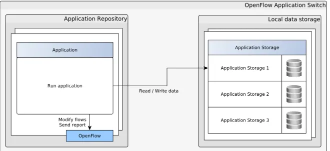
• Local data storage: Local data storage can be directly used by the applications that are executed. The main criteria for this storage is to be fast. The data can be volatile and does not need to be persisted during reboots. This can be seen as a temporary storage. Each switch has its own instance of the local data storage. The controller mayaccess or write to this database. Each application should have its own namespace in thelocal data storageto ensure that application data does not interfere.
Figure 5.2 illustrates thelocal data storageand the namespaces for sample applica-tions.
5 Concept
• Distributed data storage: The distributed data storage can be directly accessed from all application switches in the network as well as from the controller. Each switch runs its own database instance which is then synchronized across the control network. This data storage is intended for global information such as global application configuration, applications themselves or topology metadata. As synchronization across nodes introduces some overhead, this data storage should be used as little as possible.
Figure 5.3 illustrates thedistributed data storage. Several applications on several switches may all access a single database.
5.3 Local Data Plane Event Processing
Figure 5.3:Distributed data storage for application switch
5.3 Local Data Plane Event Processing
To be able to process local data plane events, the just defined local data plane applications have to be executed. The control flow as seen in Figure 2.6 needs to be intercepted. The current control flow offers several interception points. This section discusses the possible points and whether they qualify to be extended.
The following interception options are possible:
1. Injection of applications inside the kernel flow table. Application execution during the kernel packet processing.
2. Packet interception between the kernel table lookup and the user space table lookup. Application processing is done before the user space table lookup.
3. Injection of applications inside the user space flow table. Application execution is done during the user space packet processing.
4. Packet interception between the user space table lookup and the controller commu-nications. Applications are executed before the packets are sent to the controller.
5 Concept
Option (1) would be the fastest approach as applications are directly processed inside the kernel. But since application logic could be very complex, a direct processing inside the kernel does not seem very rational. As mentioned in [Pro13] the current kernel processing is as slim as possible for performance reasons.
Option (2) would require an own application table where packet headers are matched. This should be done in user space for the reasons above. This seems to be a reasonable approach but would break the existing semantics. User space flow table entries would only be looked up when no matching applications could be found. The main purpose of a switch however should still be simple packet processing.
Option (3) seems like a good extension point. The user space flow tables could be augmented with application specific actions. This enables the combination of standard OpenFlow actions and the newly introduced application. The applications would be executed in user space (unlike Option (1)).
Option (4) would be the least intrusive extension. Current state packet processing will not be modified until the packet would be passed to the controller. This means that packets would only be processed if standard OpenFlow processing could not be done. In this concept Option (3) and Option (4) are considered to be very valuable. Hence both options are considered in the concept. Other event types, such as switch port failures, will be directly forwarded to the application flow table.
5.3.1 Flow Tables
To be able to inject application actions inside the user space flow table (Option (3)) new OpenFlow actions have to be defined. An OpenFlow experimenter action can be used to encapsulate the newly defined actions. This experimenter action ensures that the newly defined actions do not break the OpenFlow specification. Hence newly defined actions can integrated into flow entries using custom OpenFlow messages.
To consider Option (3) the existing table concept had to be modified. This concept now includes the following three flow tables:
• Kernel flow table: The kernel flow table includes only flow entries that are compliant to standard OpenFlow matches and actions. No application actions can be inside the kernel flow table.
5.3 Local Data Plane Event Processing
Figure 5.4:OpenFlow application switch with application table
• Application table: The application table is a table that only includes flow entries that have application execution actions in their action sets. The flow matches can be either standard OpenFlow matches or may special matches for specific event types. No standard OpenFlow actions are allowed inside the application flow table. Figure 5.4 illustrates the newly added application flow tables. The application flow table is populated using standard OpenFlow messages. Lookups in this table will be done if there is no match in the user space flow table, for performance reasons. This ensures that standard OpenFlow processing is still preferred before executing a custom application.
5.3.2 Generic Event Processing
Generic events, such as local switch port failures (see subsection 5.1.1), are directly forwarded to the application table. This table includes non-OpenFlow matches for more generic events. The occurring event is matched against the application table and the assigned applications are executed.
For all events that generate OpenFlow messages to the controller, these messages will be sent after executing the application. The described control flow can be seen in Figure 5.5.
As an example, in case of a failed switch port, the local port failure event will be handled by an assigned port failure application. After executing the application the controller is still notified that a switch port just failed. This ensures that the controllers keep a consistent view of the network and the switches.
5 Concept
Figure 5.5:OpenFlow application switch generic event processing.
5.3.3 Ingress Packet Event Processing
Because the processing of incoming packets is the main purpose of a switch, the pro-cessing of ingress packet events is treated as a special case. The propro-cessing of ingress packets can be seen in Figure 5.6. When an ingress packet arrives at the switch, the following steps are executed:
1. The packet headers are matched against those in the kernel flow table. If they match the packet is directly processed in the kernel module.
2. If there is no match in the kernel flow table, a lookup at the user space table is performed. If this lookup is successful, the packet is processed.
3. If the user space lookup did not yield any results, the packet is looked up in the application flow table. If this lookup is successful, the corresponding application is executed.
4. If the application table lookup did not yield any results and the switch is set to fail-open, then the packet is sent to the controller. Otherwise the packet is discarded.
5.3 Local Data Plane Event Processing
5 Concept
5.4 Application Controller
After explaining the OpenFlow application switch, this sections discusses the how the controllers interact with the described applications. The communication from the controllers with the switch are done using custom OpenFlow messages.
5.4.1 Interaction with the Application Repository
In order to manage the application repository, the controllers need to be able to execute the following operations on the repository:
• Installation of applications: This operation installs an application onto the ap-plication switch. The operation must either directly supply an apap-plication or a reference to the application on one of the data storages.
• Removal of applications: This operation removes an application from the appli-cation repository. All flows entries containing this appliappli-cation in the action set should be removed prior to removing it.
• Modification of applications: This operation modifies an application on the switch. All flows entries containing this application in their action set should be removed prior to modifying it.
• Listing of applications: This operation retrieves a list of installed applications from the switch.
• Status retrieval of applications: This operation retrieves application specific status of an application.
5.4.2 Interaction with the Data Storages
The controllers have full access to the distributed storage as well as to every local storage on the switches (see subsection 5.2.3). The controllers can read and write data to these storages. This ensures that the controllers are still the most important entity and may overwrite application state if needed. The controller needs to consider that modifying local storage on the switches may break application semantics. The controller must ensure, when modifying local data storages, that the local data is consistent.
5.4 Application Controller
Figure 5.7:Communication between application switch and controller.
A scenario for global storage modification could be global failover routes for fast failover applications or the applications themselves.
Upon installing applications the controllers can populate the switch-local data storages with initial data (if needed). When removing applications form the application reposito-ries, the controllers are in charge of clearing persisted application data. If the data is not cleared by the controller, the same data storage will be used, if the removed application is installed again.
As an example, the controller might want to keep the list of saved MAC addresses in a simple switching application, when removing the application from the switch. When re-installing the simple switching application, the application is able to use the previously learned MAC addresses.
5 Concept
5.4.3 Interaction with Applications
Controllers interact indirectly with applications using the data stores. However applica-tions themselves can send two types of messages to the controllers:
• Status messages: The applications may send status messages towards the con-troller. Status messages can report any information such as application failure, application success or any other desired information.
• Standard messages: Applications may send standard OpenFlow messages, such as Packet-In or PortMod messages. For the controllers, these messages cannot be distinguished from messages that originate from standard OpenFlow processing.
5.4.4 Controller to Controller Interaction
Controllers interact with each other using the distributed data storage. This enables con-trollers to synchronize meta information about applications or their states. Furthermore controllers synchronize the available applications and required pre-defined values for these applications.
The controllers ensure that all of them keep a consistent and up-to-date view of the network. This includes standard OpenFlow information and application specific infor-mation.
For example, when a new version of a MAC learning application is introduced to a controller, the application itself will be synchronized among all controllers. This ensures that each controller uses the same applications and the same versions. Global information, such as lists of which applications are on installed on which switches are synchronized as well.
6 Implementation
This chapter describes the prototypical implementation of the concept presented in chapter 5. The prototype covers the crucial parts of the concept to verify that the concept works in a testing environment. The chapters structure is based on the structure in chapter 5. Hence, first the implementation of applications and then the handling of events is explained.
6.1 Applications
The section describes the implementation of the applications defined in subsection 5.2.1. For the prototype, two design options for applications have been considered:
• Statically compiled applications: Applications could be programmed, using the C programming language, directly in the Open vSwitch code. This allows for good debugging possibilities as well as faster code.
• Dynamically loaded applications: Applications could be dynamically loaded by the switch. This adds a great portability feature to the applications and enables the conceptual adding and removing of applications.
Both options have been prototypically implemented. The dynamic approach has been realized with linking a Lua interpreter to the Open vSwitch code. Lua is designed to be a fast, lightweight and embeddable scripting language [IdFC07]. Furthermore there are Lua bindings for the Open vSwitch libraries that would allow Lua to directly interact with the vSwitch. Lua code could be distributed using the distributed data storage to all switches.
For the implementation of the experimental use cases, code has been directly added into Open vSwitch. This is mainly due to debugging reasons. Debugging injected C code was much less complicated than debugging interpreted Lua code inside the C code. For each event type those static applications have a common function signature as exemplary seen for the event processing of ingress packets in Listing 6.1.
6 Implementation
Listing 6.1 Generic application function signature.
void applicationName(
struct flow *flow,
struct ofproto_dpif *ofproto, struct dp_packet *packet
);
The function parameters for ingress packet event applications are as follows. The depicted data structures are part of Open vSwitch.
• struct flow *flow: The flow struct represents a flow in the network. This is not to be mixed up with a flow entry in a flow table that may contain wildcards. It will contain all header fields and meta-information that triggered the handling of the application.
• struct ofproto_dpif *ofproto: An OpenFlow protocol data path interface. This allows to install and remove flow entries.
• struct dp_packet *packet: The actual packet without any meta information. This struct allows to directly access required packet information. Furthermore functions
from dp-packet.hcan be used to extract information or modify the packet.
6.2 Application Repository
The application repository has been realized as a static list of applications. For the experimental use cases this is a selector that maps an application ID to a previously defined application. The repository will then execute the application. The repository has different functions for each event type. The implemented function signatures for the application repository can be seen in Listing 6.2.
In addition to the parameters that are passed to the applications themselves, the exe-cuteApplicationAction receives the ID of the application that has to be executed. The application will then be selected and the required information will be passed to the application.
TheexecuteApplicationPortStatefunction has the following parameters:
• int applicationId: The ID of the application to be executed.
6.3 Application Storage
Listing 6.2 Application repository function signatures.
/*
* Executed on application table match or action in user space flow table. */
void executeApplicationAction(
int applicationId,
struct dp_packet *packet,
struct flow *flow,
struct ofproto_dpif *ofproto
); /*
* Executed when a switch port changes its state. */
void executeApplicationPortState(
int applicationId,
struct ofport *port,
bool alive )
TheexecuteApplicationPortStatefunction is executed when the state of a physical switch port changes. That might be a failing or a recovering switch port.
6.3 Application Storage
As described in subsection 5.2.3 the applications need two type of data storages. This sec-tion describes the implementasec-tion of these storages. The data storages are implemented using different database engines. The interfaces of both data storages can be seen in Listing 6.3. As the listing shows, the data storages are implemented as pure key-value stores. This allows for great portability and, if needed, the changing of database engines. If more complex data needs to be saved, a serialization format such as JSON [JSO14] might be used.
The function semantics for both, the local as well as the distributed data are similar. The write functions write given data to a given key. The local version of the write function allows to set an expiry time for the key. Even if technically possible, this is not permitted on the distributed data storage, as the controllers or other applications may rely on the existence of the key. The readfunctions retrieve saved data for a given key, while theexistsfunctions check whether data for a given key exists.
As applications should only locally read from and write to their own application storage, namespaces for the applications should be used when saving data.
6 Implementation
Listing 6.3 Application data storage, application_db.h
/* Initialization and initialization checks. */
int appdb_inititialize(void);
int appdb_is_initialized(void); /* Distributed data storage. */
int appdb_write(char* key, char* data);
char* appdb_read(char* key);
int appdb_exists(char* key); /* Local data storage */
int appdb_write_local(char* key, char* data, time_t expiration);
char* appdb_read_local(char* key);
int appdb_exists_local(char* key);
Listing 6.4 Application data storage prefix for local databases.
key_prefix := /applications/<application_id>/
In the experiments each application stores their required data using key prefixes as shown in Listing 6.4.
The next two sections will describe the specific implementations for the data storages.
6.3.1 Local Data Storage
The local data storage is implemented using memcached. Memcached is a high-performance in-memory key-value store for small chunks of data [NFG13]. Memcached was initially designed to act as a cache for web applications but is now used for many other applications of in-memory databases.
The ovsdb-server (see subsection 2.3.3) could be used for the same purpose. But it was found to be less convenient to integrate into the developed applications. Using the ovsdb-server would have the advantage that no additional database engine on the switch is required. On the other hand this would dilute the clean cut between the application data storage and the existing Open vSwitch configuration database.
6.4 Ingress Packet Event Processing
6.3.2 Distributed Data Storage
For the distributed data storage etcd has been used. Etcd is a distributed consistent key-value store for shared data. Etcd is developed as a part of CoreOS Linux - a container-focused operating system. The focus lies on the following principles (from [Cor]):
• Simple: curl’able user-facing API (HTTP+JSON)
• Secure: optional SSL client cert authentification
• Fast: benchmarked 1000s of write/s per instance
• Reliable: properly distributed using raft.
The raft algorithm is a consensus algorithm for managing a replicated log [OO14]. It was developed by Ongaro and Ousterhout at Stanford University in 2014 and is already used in a variety of projects.
6.4 Ingress Packet Event Processing
This section deepens the implementation of the concept for local data plane event processing as described in section 5.3. To implement the Options (3) and (4) from the concept, new OpenFlow actions had to be defined. To ensure OpenFlow compatibility, OpenFlow experimenter actions are used. Experimenter actions allow to implement custom actions without violating the OpenFlow standard. Hence application actions can be chained with standard OpenFlow actions.
6.4.1 Application Actions
In order to add custom experimenter actions into Open vSwitch, a custom vendor has to be defined. Otherwise Open vSwitch would not accept custom OpenFlow experimenter actions. The defined vendor ID can be seen in Listing 6.5. In Listing 6.6 the structure of the experimenter action can be seen. The defined subtypespecifies which experimenter action to execute. Currently only the EXECUTE_APPLICATIONexperimenter action has been fully implemented.
To add this application to the flow tables, functions to encode, decode, parse and format this struct to Open vSwitch internal data formats had to be implemented. The actual code of these functions can be seen in the Appendix A.
6 Implementation
Listing 6.5 OpenFlow vendor id, openflow-common.h
#define NX_VENDOR_ID 0x00002320 /* Nicira. */
#define ONF_VENDOR_ID 0x4f4e4600 /* Open Networking Foundation. */
#define FMS_VENDOR_ID 0x00001234 /* Vendor ID used in this thesis. */
Listing 6.6 OpenFlow experimenter action struct, ofp-actions.c
/* FMS1.0+(1): struct fms_execute_application. */ FMS_RAW_EXECUTE_APPLICATION,
/* EXECUTE_APPLICATION instruction */
struct fms_execute_application{
ovs_be16 type; /* OFPAT_EXPERIMENTER. */
ovs_be16 len; /* Length is padded to 64 bits. */ ovs_be32 experimenter; /* FMS_VENDOR_ID. */
ovs_be16 subtype; /* FMS_RAW_EXECUTE_APPLICATION */ uint8_t application_id;
bool slow_action; uint8_t pad[2]; };
6.4.2 Flow Tables
The application table, as described in subsection 5.3.1, is currently implemented as a special OpenFlow table. After implementing the experimenter actions, this is rather a logical than a technical separation. The application table is simulated using a special flow table which will only contain match-action pairs that will executed applications. In order to obtain the packet flow as described in Figure 5.6, low priority catch-all flow entries are installed into the other flow tables. These catch-all flow table entries will forward packets to the application table if no other flow entry matched. On matching packets the application table will execute the referenced applications. Otherwise the packet will be forwarded to the controller.
6.5 Generic Event Processing
Generic event processing has been implemented for changes in port states. This allows to locally react to failing or recovering switch ports.
In order to execute applications on port changes, code had to be added toofproto.c, right before the switch informs the controller of a new port state. As seen in Listing 6.7, the
6.6 Application Controller
Listing 6.7 Handling of port change events, ofproto.c
static void
ofport_modified(struct ofport *port, struct ofputil_phy_port *pp)
{ [...] if(port->pp.state == OFPUTIL_PS_LINK_DOWN || port->pp.state == OFPUTIL_PS_LINK_DOWN || port->pp.config == OFPUTIL_PC_PORT_DOWN) {
VLOG_INFO("Link is down: %"PRIu16, port->ofp_port); executeApplicationPortState(1, port, false);
}
else
{
VLOG_INFO("Link is up: %"PRIu16, port->ofp_port); executeApplicationPortState(1, port, true); }
[...] }
This differs from the application table proposed in the concept, where generic processing and the processing of ingress packets is done in the same application table. The reason for this deviation from the concept is that OpenFlow tables are used for the processing of ingress packets. Using a standard OpenFlow tables allowed to use existing Open vSwitch logic for the matching of ingress packets, but disallowed to match anything that is not an ingress packet. Hence a static function call from the port failure event to the associated application has been implemented.
6.6 Application Controller
To enable the controllers to send application specific instructions to the switches, custom OpenFlow messages had to be implemented. The implementation used OpenFlow experimenter messages, to not violate the OpenFlow standard. The same vendor ID as for the experimenter action has been used (see Listing 6.5).
The structs for the messages can be seen in Listing 6.8. Currently these messages are implemented as stubs, as the experimental use cases are directly coded into Open vSwitch. Hence no implementation for the installation and removal messages was needed.
When implementing the installation and removal of dynamic applications, the applica-tions need to be distributed among all controllers using the distributed data storages.
6 Implementation
Listing 6.8 Implemented OpenFlow experimenter messages, ofp-msgs.h
/* FMS extensions. */ OFPTYPE_APPLICATION_INSTALL, /* OFPRAW_FMS_APPLICATION_INSTALL. */ OFPTYPE_APPLICATION_REMOVE, /* OFPRAW_FMS_APPLICATION_REMOVE. */ /* FMS 1.0+ (1): struct fms_application. */ OFPRAW_FMS_APPLICATION_INSTALL, /* FMS 1.0+ (2): struct fms_application. */ OFPRAW_FMS_APPLICATION_REMOVE, struct fms_application {
struct ofp_header header;
ovs_be32 vendor; /* FMS_VENDOR_ID */
ovs_be32 subtype; /* Action type. See OFPRAW_FMS_* in ofp-msgs.h */ ovs_be32 application_id;
ovs_be32 is_active; };
Controllers then can install application on the switches by sending installation messages to the switch. The installation message contains an ID and a location of the application on the distributed storage. The switch will retrieve the application from the distributed storage and installs the application into the application repository. To remove an applica-tion, a controller will send a application removal message. Upon receiving the removal message, the switch will remove the application from its application repository.
6.7 Implementation of Use Cases
This section covers the implementation of the use cases which are used for the evaluation of the concept and the prototype. Each use case application has been implemented directly in Open vSwitch using C. The same applications are implemented as a Ryu modules using Python as well.
6.7.1 Use Case #1 Port Knocking
Port knocking is a technique that opens a firewall for a client, after the client has knocked (by sending TCP-SYN or UDP-Packets) at certain ports in a previously defined sequence.
6.7 Implementation of Use Cases
The port knocking application is triggered by incoming packets at the switch. Figure 6.1 shows the conceptual implementation of the use case. For the ease of implementation a fixed set of four knocking ports was used. Furthermore the application only reacts to UDP packets.
For each ingress UDP packet, the current state for the sender of the UDP packet is retrieved. The current state denotes in which port knocking stage the sender is. If the UDP port of the ingress packet equals the port to reach the next stage, the next stage is assigned. If the port is not equal, the starting stage is assigned. If the sender reaches the “open” stage, flow entries to allow other traffic are installed. The current stage is persisted using the local data storage is used.
6.7.2 Use Case #2 Multicasting
This use case takes care of an IP multicasting scenario. In the remote controller approach the switch forwards host membership report messages to the controller. The controller then decides which rules to install (in the global network) and makes sure that the requesting host receives the multicast traffic for the requested groups. This is done for every host that joins or leaves a multicasting group. The controller keeps track of the multicast members and installs or removes flow entries.
In this scenario the switch keeps track of multicasting members and only informs the controller if global rule changes may need to be done. There are only two cases when this might happen:
1. The first member of a group joins. 2. The last member of a group leaves.
Both cases may yield global rule changes. For the first case the controller might need to install flow entries to ensure that multicasting traffic for the requested group is actually received by the switch. For the latter case the controller might remove these flow entries.
In all other cases when a group member joins or leaves the switch can adjust his local flow entries to make sure that those hosts receive the multicasting traffic. No global action is needed as the switch already receives the requested traffic.
The multicasting application is triggered by incoming packets at the switch. Figure 6.2 depicts the implemented control flow.
For each IGMP membership report message the application checks whether the host wants to join or leave a group. Depending on this, the following is executed:
6 Implementation