A Novel Physical Layer Secure Key Generation and
Refreshment Scheme for Wireless Sensor Networks
Moara-Nkwe, Kemedi, Shi, Qi, Lee, Gyu Myoung and Hashem Eiza,
Mahmoud
Available at http://clok.uclan.ac.uk/21665/
MoaraNkwe, Kemedi, Shi, Qi, Lee, Gyu Myoung and Hashem Eiza, Mahmoud ORCID: 0000
000191148577 (2018) A Novel Physical Layer Secure Key Generation and Refreshment Scheme
for Wireless Sensor Networks. IEEE Access . pp. 114. ISSN 21693536
It is advisable to refer to the publisher’s version if you intend to cite from the work.
http://dx.doi.org/10.1109/ACCESS.2018.2806423
For more information about UCLan’s research in this area go to
http://www.uclan.ac.uk/researchgroups/ and search for <name of research Group>.
For information about Research generally at UCLan please go to
http://www.uclan.ac.uk/research/
All outputs in CLoK are protected by Intellectual Property Rights law, including
Copyright law. Copyright, IPR and Moral Rights for the works on this site are retained
by the individual authors and/or other copyright owners. Terms and conditions for use
of this material are defined in the http://clok.uclan.ac.uk/policies/
CLoK
Central Lancashire online Knowledge
Digital Object Identifier ******************/ACCESS.2017.DOI
A Novel Physical Layer Secure Key
Generation and Refreshment Scheme for
Wireless Sensor Networks
KEMEDI MOARA-NKWE1, QI SHI1, GYU MYOUNG LEE1AND MAHMOUD HASHEM EIZA2
1Department of Computer Science, Liverpool John Moores University, UK 2School of Physical Sciences and Computing, University of Central Lancashire, UK
Corresponding author: Kemedi Moara-Nkwe (e-mail: [email protected]).
ABSTRACT Physical Layer Secure Key Generation (PL-SKG) schemes have received a lot of attention
from the wireless security community in recent years because of the potential benefits that they could bring to the security landscape. These schemes aim to strengthen current security protocols by reducing the amount of key material that devices need for deployment. They do this by harnessing the common source of randomness provided by the wireless channel that the physical layer is communicating over. This is of particular importance in Wireless Sensor Networks (WSNs) where resources are particularly scarce and where issues such as key revocation and recovery make the design of efficient key management schemes extremely difficult. This paper discusses the issues and challenges encountered in the design and implementation of PL-SKG schemes on off-the-shelf wireless sensor networks. It then proposes a novel key generation scheme that takes advantage of both the power and simplicity of classic error correcting codes and also the diversity of frequency channels available on 802.15.4 compliant nodes to generate keys from received signal strength (RSS) readings. This paper shows that our key generation and refreshment scheme can achieve a near 100% key reconciliation rate whilst also providing perfect forward and backward security.
INDEX TERMS Key Refreshment, Physical Layer Security, Secure Key Generation, Wireless Sensor
Networks.
I. INTRODUCTION
Wireless Sensor Networks (WSNs) have grown in popu-larity over the last few decades because of their relatively low cost and their ease of deployment but such networks pose significant design challenges because of their limited computational prowess and their short battery life [1] [2]. In the context of wireless security, WSNs pose significant chal-lenges because their limited capabilities render conventional key management techniques such as public key cryptogra-phy based schemes impractical. Elliptic curve cryptogracryptogra-phy (ECC) based schemes implemented on WSN nodes such as TinyECC [3] will, for example, consume significant energy resources and even then a single operation will still take a long time to compute [4].
Physical Layer Secure Key Generation (PL-SKG) schemes aim to address the challenges highlighted above by enabling a key to be generated and refreshed in a relatively lightweight manner [5] [6]. They achieve this feat by exploiting the diversity and inherent randomness of the wireless channel
that the physical layer is communicating over to generate keys. Another key advantage of PL-SKG schemes is that they use secondary packet information (e.g Receive Signal Strength (RSS), Link Quality Indicators (LQI), Automatic Gain Control (AGC) Information e.t.c) to generate keys. Hence, the same packets that are being exchanged during the key generation process could still be used to carry other application specific information that nodes may wish to exchange, and in so doing preserving bandwidth.
The work in this area stems primarily from initial work by Mathur et al. [7] and Azimi-Sadjadi et al. [8] showing that given that there is a fading channel between two communi-cating parties, a common secret key could be extracted by those two parties. Following this, there have been a number of studies that looked into this issue in the WSN domain. This work has mainly consisted of looking at only mobile WSNs although work in [4] was the first to look at static channels (i.e where nodes are not moving). Despite the progress that has been made in these areas, there is still a
number of limitations like unguaranteed key establishment in all environments which hamper the wide spread adoption of these schemes. Some of these issues have been addressed by the PL-SKG scheme proposed in this paper.
PL-SKG schemes usually start with a process of sampling a wireless channel and observing some physical layer parame-ter. After repeated observations of the parameter of interest, these schemes formulate a common key using their respective observations. However, it is likely that the keys generated by two different parties contain some disagreed bits. This key bit disagreement needs to be reconciled before the key can be used. Current state-of-the-art practical implementations for WSNs usually accomplish this task by exchanging some information that characterises the structure of the keys they have just generated. This can be a big security risk as it may allow an adversary to obtain and recover portions of the key given particular channel conditions. In addition to this, current RSS based PL-SKG schemes quantise the RSS directly which can cause key disagreements if the commu-nicating parties are using very different transmit powers. After reconciliation, the process moves onto the privacy amplification stage where the reconciled keys are usually hashed to ensure that the key entropy is spread evenly across the entire key size. This can then be followed by a challenge-response to ensure generated cryptographic keys agree at both ends.
Motivated by the above limitations, this paper proposes a new lightweight PL-SKG protocol for static networks, which uses Error Correcting Codes (ECCs) to reconcile keys in a secure manner that does not involve leaking any information about the formulated keys. The scheme also ensures that transmit power mismatches between nodes do not hinder the key generation process by not directly using the quantised RSS values for key formulation. The scheme uses ECCs to carry out the key reconciliation process and in so doing not revealing anything about the structure of the RSS samples. This provides an improvement on current WSN PL-SKG schemes as no information that characterises the RSS samples accumulated by legitimate parties during the randomness sharing phase needs to exchanged in the key reconciliation phase.
The main novel contributions of this paper are to
• Propose a novel, robust and practical PL-SKG scheme for static WSNs, which uses ECCs to generate and/or re-fresh keys whilst not leaking any information to a local adversary. This is in contrast to the iterative quantisation techniques that are usually used in current WSN PL-SKG schemes.
• Highlight the many implementation issues that arise when implementing PL-SKG schemes on off-the-shelf devices. Many of these issues have not been discussed in detail in existing literature.
• Provide real PL-SKG implementation results of the proposed scheme and evaluate outcomes.
This paper is structured as follows. Section II takes a look at related work. Section III gives the system and adversarial models used in our scheme. Section IV presents a broad overview of our proposed PL-SKG scheme. Sections V, VI and VII then provide detailed descriptions of our pro-posed PL-SKG scheme’s randomness sharing, information reconciliation and privacy amplification stages, respectively. Section VIII discusses the implementation of the scheme and evaluates its outcomes. Lastly section IX ends the paper by concluding and briefly discussing further work.
II. RELATED WORK
There are a lot of challenges that face PL-SKG. The most important ones are reliability of the key generation process and susceptibility to physical layer attacks such as jamming, channel manipulation and man in the middle attacks [9]. There has been a lot of research work looking into PL-SKG in WSNs in the past few years. Most of the research focuses on using RSS as a source of randomness for practical key generation. This is most likely owing to the relative ease of getting hold of RSS information as opposed to other channel state information (CSI) such as the channel response (h) on standard 802.15.4 compliant wireless nodes.
The work in [10] [11] considers key generation between mo-bile nodes using RSS as the source of common randomness and under many different topologies. It focuses on exploiting not only the wireless channel between two nodes but also the deployment environment, in which multiple nodes might be deployed, and the mobility of the nodes to generate group keys over the physical layer.
The paper [12] proposes a physical layer key generation scheme that uses nodes fitted with a special Espar antenna. The general idea is that by varying the reactances (amplitude and phase characteristics) of the Espar antennas at both ends of the communication channel, the variation of the received RSS at both ends can be induced to achieve a high key generation rate even on a static channel. This exploits not only the variation in the wireless channel but also the variation in the effective receive and transmit power that an Espar antenna experiences in the reactance domain. These variations can be exploited by building a RSS profile under different reactance values, which is used as a basis for SKG. The main problem with using the channel response as the basis for SKG in WSNs like the above existing approaches is that the channel response will not be available to higher layers on off-the-shelf (OTS) WSN devices. This forces practical SKG schemes in WSNs to resort to using coarse measures of channel randomness such as signal received strength (RSS). Such schemes include those in [13] and [4] which generate keys over the physical layer using RSS
measurements. They attempt to induce variability in static channels by switching between multiple channels centred at different frequencies. These proposed schemes have the dis-advantage of requiring that the information that characterises the structure of the generated keys needs to be exchanged as part of the key reconciliation process. They also use the quantised RSS directly in the key generation process and so transmit power mismatches between communicating parties lead to high key disagreement rates. This paper aims to rectify these problems.
III. SYSTEM MODEL
A. WIRELESS CHANNEL MODEL
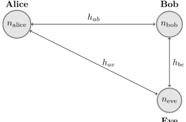
PL-SKG schemes aim to generate cryptographic keys by observing the physical channel between two nodes and using the channel as a common source of randomness upon which to generate keys. The wireless channel is modelled as being comprised of two main components: i) a multiplicative fading lossh(which we will in this text just refer to as the ‘channel’) and ii) an additive noise componentn. When a nodenalice sends a symbolxto another nodenbob,nbobreceives a noisy signalyab whereyab = hab∗x+nab with∗ being the convolution operation. Conversely, when nbob sends x to
nalice,nalicereceivesyba=hba∗x+nba[14].
The additive noise componentsnabandnbaare independent random variables, so they can not be used as a common source of randomness [15] [16]. For a static channel, the fading componentshabandhbastay highly correlated over a coherence bandwidth (Bc) because of the channel reciprocity principle. If the frequency used bynaliceandnbobis within that band, thenhab≈hba.
In the case of a non-static mobile channel, channel fading will stay highly correlated for time intervals shorter than the coherence timetcprovided that the frequency remains within the bandBc(wheretc is directly proportional to the relative speed at which nodes move). A third node neve which is a distance d away from nbob and receiving a noisy signal fromnalicewill receiveyae =hae∗x+nae, wherehae decorrelates with respect tohabasdincreases. At a distance
d ≥ λ/2 (where λ is the wavelength of the transmitted signal), it can be shown that the fading components seen by
nalice andnbob will be largely independent ofhae making it impossible for neve to estimate hab from that position. Figure 1 shows the relationship between channels between
nalice,nbobandneve.
The central idea behind PL-SKG is to utilise this channel reciprocity to generate cryptographic keys. Particularly, be-cause the legitimate channel (hab) will be in deep fade at different locations to the eavesdropper channel (hae),nalice andnbobcan use the knowledge of the channel’s deep fading characteristics to generate keys.
nalice nbob neve hab hae hbe Alice Bob Eve FIGURE 1. Channels betweennalice,nbobandneve.
B. ADVERSARIAL MODEL
It is important to outline the assumptions made about the adversary’s computational and physical advantages just as in conventional cryptographic protocols. The adversary in this case is modelled as being active and in the reception range of all packets exchanged betweennaliceandnbob. The adversary,neve, is also assumed to be at a distance greater than 2m from both nalice andnbob. If the adversary is too close to naliceandnbob then the adversary’s channel might correlate with legitimate party channels. The adversary is also capable of both power limited indiscriminate jamming of the 2.4GHz spectrum and also capable of flooding the wireless channel.
Given the assumptions above, the attacker must not be able to recover the common key generated bynaliceandnbob or use a compromised session key to calculate session keys that were used prior to or after the compromised session.
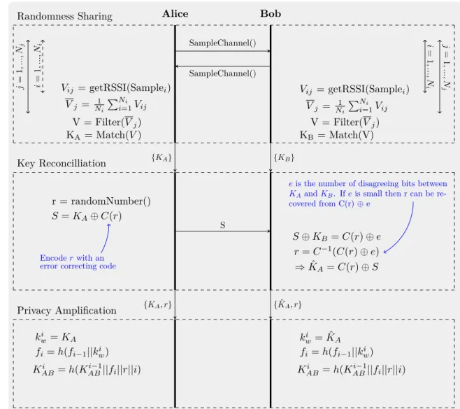
IV. OVERVIEW OF PROPOSED PL-SKG SCHEME The proposed PL-SKG scheme consists of three main stages as shown in Figure 2. These are i) randomness sharing, ii) key reconciliation, and iii) privacy amplification. In the randomness sharing phase,naliceandnbobtradeNimessages over Nj different frequencies. They then filter and process those samples as shown in Figure 2 to formulate an initial key.
In the key reconciliation stage, that key is reconciled using ECCs. This process involves nalice generating a random number and encoding it with an ECC. A one-time pad is then performed with the encoded random number and the key that has been generated by nalice and the result is sent over the wireless channel to nbob. nbob then processes the information received as shown in Figure 2 to reconcile its key with the key generated by nalice. After bothnalice and
nbob have generated the keys, the process moves on to the privacy amplification stage.
The privacy amplification stage serves two main purposes, i) to ensure perfect forward and backward security and ii) to ensure that the final key has bits which are well distributed. To achieve this goal, the privacy amplification stage formulates the key in such a way that a new session key forms a hash chain that uses both the previous key and the hashed value of the current physical layer generated key as arguments. Formulating the current session key in this manner makes it impossible for an intruder with knowledge of compromised session keyKito compute the key that was used prior to or afterKi. The details of these three stages will be presented in the separate sections below.
V. RANDOMNESS SHARING & QUANTISATION
Randomness sharing is arguably the most important stage in the PL-SKG process because it is the stage when a physical layer parameter (in our case the RSS) is observed. In this section we will first look at the limitations and the implementation issues that arise when using OTS 802.15.4 compliant WSNs. We will then briefly investigate the impact that channel fading has on the variability of static WSN channels, before detailing the full procedure for randomness sharing used in our proposed PL-SKG scheme.
A. IMPLEMENTATION ISSUES WITH RANDOMNESS SHARING ON REAL NODES
A WSN node consists of sensors, a transceiver and a mi-crocontroller. A user wishing to deploy a PL-SKG scheme has the option of i) performing the entire key generation procedure in hardware within the transceiver where all the other physical layer tasks are performed, or ii) just sampling a physical layer parameter from the transceiver and using that parameter as a source of randomness for a key generation procedure taking place in the microcontroller. Opting for the former solution would mean using the transceiver with physical layer functions for key generation built in, which would hinder quick adoption and deployment of the scheme. The latter option involves employing a current 802.15.4 com-pliant transceiver (such as the popular CC2420 transceiver [17] used in TeloB WSN nodes) which is used in nodes to sample a physical layer variable such as the RSS and have the other stages of SKG implemented as software on the microcontroller. This approach has been the most popular one used in practical WSNs and was adopted in [4] [10]. The most useful and hence most intuitive channel parameter to use as a shared source of randomness between two parties is the channel response (or multiplicative fading loss) h. The channel response encapsulates the amplitude and phase changes that a transmitted signal goes through whilst travel-ling through the wireless medium. The channel response also has two degrees of freedom upon which to generate keys -the channel amplitude and -the channel phase - and will thus yield a better key generation rate than parameters with just one degree of freedom. When trying to generate physical
layer keys using OTS transceivers, the channel response will be most likely unavailable, so another parameter such as the RSS might be used instead. OTS transceivers do not compute and pass on a channel response estimate because it is not directly needed for communication to occur so it does not warrant the additional computational resources it would take to estimate and provide it. Even if the channel response was estimated and provided on a symbol-by-symbol basis, a device running at a frequency much higher than a microcontroller’s frequency would be needed to sample the values.
B. SOURCES OF CHANNEL FADING IN WSNS
PL-SKG schemes rely on sampling the channel response
h and thus the rate at which we can generate keys at the physical layer is limited by how much the channel varies in time, frequency and space. If a node is moving, the frequency received will differ from the frequency transmitted according to the formula 1 below because of the Doppler shift [18, p. 47]. The relationship between the receive and transmit frequenciesfRX andfT X is defined below:
fRX=fTX+ ∆f =fTX+ ||~v(t)|| λ cosθ(t) =fTX+fMAXcosθ(t) (1)
Here,−−→v(t)is the relative velocity between the two nodes,λis the wavelength of the transmitted wave,θ(t)is the angle of signal arrival at timet, andfM AX is the maximum Doppler shift.
This shift causes a time-varying channel and fast fading. The coherence time tc is the time interval where we have
fRX≈fTX. In the case of mobile nodes, this variability can
be exploited to generate keys by sampling the channel everyt
seconds wheret > tc. In the case of static nodes, where −−→
v(t)
= 0, there is no time-varying channel fading, so the channel remains largely unchanged for a long period, which reduces the key generation capacity.
There is also an opportunity to exploit the frequency selective characteristics of a channel to generate keys. Frequency selectivity is caused by the propagating environment in which the nodes are communicating and the rate at which nodes are transmitting data. Frequency selectivity when transmitting symbols over a channel is caused by multipath propagation which causes time dispersion, leading to Inter-Symbol In-terference (ISI). Multipath propagation results in different copies of a signal to take different paths from a transmitter to a receiver. Since these paths are of different lengths, they arrive at the receiver at different times and cause ISI. The coherence bandwidth is a statistical measurement of the range of frequencies over which the channel can be
Alice Bob SampleChannel() SampleChannel() Randomness Sharing i = 1 ,..., Ni j = 1 ,..., Nj Vij = getRSSI(Samplei) Vj = N1iPNi=1i Vij V = Filter(Vj) KA= Match(V) i = 1 ,..., N i j = 1 ,..., N j Vij = getRSSI(Samplei) Vj = N1iPNi=1i Vij V = Filter(Vj) KB = Match(V) S Key Reconcilliation r = randomNumber() S=KA⊕C(r) S⊕KB =C(r)⊕e r=C−1(C(r)⊕e) ⇒KˆA=C(r)⊕S {KA} {KB} Encoderwith an error correcting code
eis the number of disagreeing bits between KAandKB. Ifeis small then r can be re-covered from C(r)⊕e Privacy Amplification ki w=KA kwi = ˆKA fi=h(fi−1||kwi) fi=h(fi−1||kiw) Ki AB=h(KABi−1||fi||r||i) KABi =h(KABi−1||fi||r||i) {KA, r} {KˆA, r}
FIGURE 2. Figure Showing Key Generation and Refreshment Process.
considered flat. The X% coherence bandwidth is defined in [19, p. 47] as being equal to the value of∆f such that:
X
100 =
E{h(f)∗h(f + ∆f)}
E{|h(f)|2} (2)
Here,Xis the correlation factor,h(f)is the channel response at frequency f,|h(f)|is the channel gain andE{x} is the expectation of random variable x. The 50% and the 90% coherence bandwidth, for example, can be shown to be equal to 1/5στ and 1/50στ respectively. Here, στ is the delay spread.
For a channel to be very frequency selective, we usually need to have a signal bandwidth greater than the 50% channel coherence bandwidth, namely we needBs> BC,50. In
non-line-of-sight indoor WSNs we will typically have the value ofστin the range from≈8ns to≈18ns [20] and an allocated bandwidth of 2MHz per channel in 802.15.4 networks. Hence
we can see that even if we take the most severe case of delay spread given as 18ns in [20] we have BC,50 ≈ 11MHz.
This means that just one channel does not provide enough frequency dependent variation to base key generation on, but if we use the entire spectrum of available 802.15.4 channels we can exploit the fact that each individual channel has a different frequency response to generate keys.
The above problem with static channels not having a lot of variability is a key challenge when trying to formulate PL-SKG schemes for WSNs as nodes are usually non-mobile and utilise low bandwidths. A common approach to circumvent-ing this problem is to induce variability at the nodes by limit-ing the schemes to mobile nodes [10], switchlimit-ing transmission channels [4] or altering hardware characteristics every time we sample the channel [12]. The presence of some frequency selective fading means that we can exploit the variability of slow fading loss (Lp) at different centre frequencies by switching between different frequency channels.
C. RANDOMNESS SHARING IN PROPOSED PL-SKG SCHEME
The scheme we propose alternatively hops betweenL chan-nels according to a pre-determined frequency hopping sched-ule S known to both nodes nalice andnbob and computes the mean RSS on each channel at each end. In order for the nodes to generate keys they need to change their frequency channels synchronously, and the frequency hopping schedule
S helps them do that. The schedule also plays an important part in ensuring that the generated keys vary with time even in static channels. Going through the key generation process multiple times in quick succession will still produce different keys because the set of channels used and the order in which they are used will change with each iteration according to the synchronised schedule S. The generation of S can be arbitrary and so legitimate parties can easily generateS by seeding a pseudo number generator and iterating it after every sample period.
After this, the samples are first processed by removing the direct current (DC) component in the samples (this involves calculating the mean of the samples and then deducting that mean from each sample value). The average value (i.e mean) of the resulting samples after this processing will then be zero. This is done so that the differences in transmit powers between nalice and nbob do not affect the key generation process. After this, each value in the resulting sequence is matched and swapped with its gray code equivalent. Convert-ing to gray code helps minimise bit disagreement between
naliceandnbob by ensuring that the difference between any two adjacent values is zero.
After this we take our bit sequence and use it to formulate a weak key. In this case we will define the weak key as the intermediate key that comes out as a result of the randomness sharing phase and is used in the key reconciliation process. If we need a longer weak key, we can change the schedule
S and repeat the process above to get another longer bit se-quence. We can repeat this process until we have the required number of bits in our weak key, although the longer the key required the higher the energy cost. The rationale behind formulating weak keys in this way and not just using directly quantised values is to further add resilience to transmit power differences between nodes that would otherwise cause mis-matches and to increase the key variability between sessions. The randomness sharing procedure is shown in algorithm 1.
VI. INFORMATION RECONCILIATION
Information reconciliation is the process of using quantised values of a physical parameter to generate a common key be-tween two communicating parties. This stage aims to reduce the bit errors between two communicating nodes by having the nodes share some information that would help them reconcile their keys. The main existing approaches proposed of doing this include the use of error correcting codes or the exchange of some information regarding the quantisation of
Input:Channel Frequency Hopping ScheduleS
Result:KRS - Key from Randomness Sharing Stage
foreach channel indexj∈[1, Nj]do Channel Frequency←S(j);
foreach sample numberi∈[1, Ni]do
Vij ←getRSSI(Samplei); end Vj=(1/Ni)×PNi=1i Vij; end V =(1/Nj)×P Nj j=1Vj;
foreach channel indexj∈[1, Nj]do
KRS(j)←convertToMatchingGrayCode(Vj-V);
end
Algorithm 1:Pseudocode for Randomness Sharing Stage
keys to help reconcile keys. The former approach is popular in 802.11 networks (particularly using LDPC (Low Den-sity Parity Check) codes (ECCs) or BCH (Bose-Chaudhuri-Hocquenghem) codes) whilst the later approach is popular in a WSN setting.
The use of the ECCs process involves nalice choosing a random number, r, encoded with an error correcting code
C, performing a one-time pad with its key Ka to create a syndromeS, and sending it tonbob.nbobthen performs a one-time pad with its keyKb to get an estimate of the encoded data and then uses it to compute Ka. More formally, the above process can be defined as follows:
Alice : s=C(r)⊕Ka Bob : ˆ r=Decode(s⊕Kb) =Decode(C(r)⊕Ka⊕Kb) =Decode(C(r)⊕e) =r (ifHD(e,0)<some thresholdt) =⇒ Kˆa =C(ˆr)⊕s (3)
Here, the bitwise⊕operation is the exclusive OR operation,
eis the error vector and HD(a, b)is the hamming distance (i.e the number of disagreeing bits) between numbersaand
b.
The choice of ECC in a WSN setting will depend on the required key length as different codes have different decoding capabilities and resource requirements. The hamming code, for example, is fairly easier than other resource intensive codes such as LDPC codes to implement but it will only have a decoding threshold of t = (dmin−1)/2, wheredmin is the minimum distance between codes, whilst LDPC codes can correct many more errors as the key size increases but consumes more resources because of its iterative decoding
process.
The chosen ECC needs to be able to correct errors but it should not be able to correct a large number of errors. If the ECC can correct a large number of errors then it may be possible forneveto reconcile its key withnaliceeven though the difference between their keys is fairly large. Hamming and Polynomial codes have the advantage of having a clearly defined error correcting capability, so we know that they will only be able correct errors up to a fixed threshold. Polynomial codes are similar to hamming codes in terms of both error correction capability and resource intensiveness, so we propose the use of either hamming codes or polynomial codes for error correction.
Polynomial codes create a codeword c(x) by using the original message vector m(x) and a primitive polynomial
g(x), wherec(x),m(x)andg(x)are all in polynomials with coefficients belonging to the Galois field of two elements (i.e GF(2)). The code can correct one bit error in the received messager(x)by computing the remainder after dividingr(x)
withg(x). This can be seen below:
c(x) =m(x)g(x) r(x) =c(x) +e(x) rem r(x) g(x) =rem c(x) +e(x) g(x) =rem e(x) g(x)
Here, e(x) is the error monomial. The set of all values of remgx(xi) for all i (i.e. for all error monomials) is precomputed and stored in a look-up table and thus the error location ican be computed at the receiver provided only a one bit error has occurred.
A hamming code is specified by a generator matrixGand a parity check matrixH such thatHGT = 0. The code is computed asc =mGand the received vector~r =~c+~eis decoded by first computing a value called the syndrome,s, bys = HrT and comparing which column of parity check matrixHmatches withs. Here, the message vector ismand the error vector ise. The matched column is the error location of the single bit error. If s = 0, then there is no error. A polynomial code with a message lengthkand a code length
ncan be represented as a cyclic hamming code by setting:
G= g(x) xg(x) ... xkg(x) T (4) H= remgx(x1) T ... remgx(nx) T (5)
The design of our proposed scheme uses a series of Hamming codes with an additional parity bit with a code length of n = 8 and message length k = 4 to achieve error correction. Using a small code length helps keep the complexity of the key reconciliation stage low. The key is first interleaved by using a (4×8) block interleaver before encoding. Interleaving is used in order to make the ECC more robust to burst errors so the scheme works even if a particular segment of the key has a high density of errors.
The interleaved key is first divided intonchunks, and each chunk is then padded with a Hamming code encoded random bit sequence (C(r)) to form a set of syndromes. Afterwards, these syndromes are then sent from nodenaliceto nodenbob for nbob to carry out key reconciliation. When nbob first receives the set of syndromes, nbob performs the following for each syndrome. nbob first tries to recover the original encoded key segment by performing a one time pad of the received syndrome with the key that nbob has measured. After performing this operation,nbobwill obtain the original encoded random number withHD(e,0)errors, whereeis the error vector (Ka⊕Kb).
Using the error vector e, nbob can then recover the origi-nal error free encoded random sequenceC(r)by decoding
C(r)⊕e to getr and then encoding the result to recover
C(r). After this, the key measured bynalicecan be recovered by computing C(r)⊕s. The random number, r (which is encoded to createC(r)), is generated using the Park-Miller Minimal Standard Generator. The Park-Miller Minimal Stan-dard Generator is a multiplicative linear congruential gen-erator (r = (a×s)mod(231 −1)) with a = 16007 and
the initial seed value s sourced by our scheme from the lower bits of the transceiver’s automatic gain control (AGC) magnitude register (the transceiver datasheet specifies that these lower bits can be used for random number generation). After error correction bothnaliceandnbob can then proceed to the privacy amplification stage.
VII. PRIVACY AMPLIFICATION
The general idea behind privacy amplification is to ensure that if the number of bits in the key generated after reconcil-iation by a key generation scheme is greater than the entropy of the key, we need to adjust the size of the key so that it aligns well with the entropy of the key. Take for example the following reconciled 32 bit key,KAB, that was quantised by looking at the number of deep fades that a chip sequence experienced whilst travelling over a channel (deep fade = 0):
KAB= 10111101111111111110111011111101 H(KAB) =length(KAB)× Pr(0) log2 1 Pr(0)+Pr(1) log2 1 Pr(1) << length(KAB) (6) VOLUME 4, 2016 7
Here,H(KAB)is the entropy ofKAB. So we need to have the key to be of lengthl≈H(KAB)<length(KAB)for the key to have a level of cryptographic security that corresponds to its length. This can be done by using privacy extractors or by hashing the long key and choosing the firstn bits of
H(KAB)as the final keyKAMP.
KAB= 10111101111111111110111011111101
KAMP=h(KAB)|
BIT(n−1)
BIT 0
(7) The calculations above assume neveobserves a completely decorrelated channel fromnaliceandnbob. In order to eval-uatenwe would need to knowneve’s channel statistics and thus in our scheme we takenas being equal to length(KAB) meaning that the resultant generated key will have a length that is longer than its true entropy. This keeps the complexity and hence the computational cost low.
In our proposed key generation scheme, we propose that the privacy amplification should be done in a way that the generated keys refresh the current session key to formulate the next session key and in so doing form a hashed key chain. In other words, a physical layer generated key in this time instance is a function of all the previous keys that have ever been generated. This can be achieved by computing the final key KABi using the previous session key KABi−1, reconciled weak keyki
w, the recovered random numberrand the iteration numberias:
KABi =h(KABi−1||fi||r||i)
fi=h(fi−1||kiw)
(8) Here, fi is a hash chain of reconciled weak keys, with
f0=h(kw0).fiis used to ensure that only a node with knowl-edge of all previous key generation sessions can generate the next session key. After naliceandnbob have derived a key, challenge-response authentication can then be undertaken to make sure the two generated keys agree. If the two keys do not agree then key generation can be attempted again. This will prevent key error propagation, where one error leads to more errors in the subsequent keys. The derived Ki
AB can
then be used for communication betweennaliceandnbob. VIII. IMPLEMENTATION, EVALUATION AND
COMPARISION
In order to evaluate the practicality of our proposed PL-SKG scheme and compare it with the most relevant existing method in [4] as will be elaborated later, we have imple-mented them using the NesC language [21] on a pair of TelosB WSN nodes running the TinyOS operating system. Experiments in a line-of-sight (LOS), indoor office setting were run over a number of distances and at a number of transmit power levels in order for the correlation between these factors and the Successful Key Reconciliation (SKR) to be evaluated. The nodes were static during the key gen-eration process and the environment was an office working
environment. The RSS values used are the ones measured and reported by the CC2420 transceiver that constitute the TelosB nodes under test. The CC2420 has a stated RSS dynamic range of 100dB and a stated RSS accuracy of ±6dB with RSS linearity of ±3dB. The graphs showing the observed SKR vs distance relations can be seen in Figures 3 - 4. The graphs also show the distance between nodes versus the SKR rate at different transmit powers. Each curve in the graphs is a third order polynomial best fit curve of the data points. From the graphs, it is clear to see that the SKR is very high (near 100%) at short distances but decreases with the distance and also decreases with lower node transmit powers. These results show that PL-SKG can be a suitable alternative for the implementation of soft key generation in WSN nodes. In particular, a key can be generated and used to refresh session keys of a WSN node and in so doing help to enforce the forward security of the WSN node. This would make it very hard for an attacker who does not have all the keys generated over all previous key generation sessions to discover the current key.
As the distance betweennaliceandnbobincreases, the signal-to-noise (SNR) ratio at the receiving end decreases. This decrease in SNR makes the estimation of the reciprocal component of the channel (and hence the RSS) harder. From the RSS we have RSS ≈ Pr+Pn ±3. Here the±3 dB component is due to the stated linearity in the calculation of RSS on the TelosB’s transceiver [17]. As the distance increases (or the transmit power reduces) the receive power (Pr) reduces. This reduction inPr causes the share of the non-reciprocal component of the RSS (Pn ±3) to increase as a proportion of the total RSS. This then causes bigger disagreements in measured RSS between nalice and nbob. This then reduces the SKR rate. This is clearly visible by looking at the shapes of the curves in Figures 3 - 4.
In order to evaluate the performance of the proposed PL-SKG scheme, we have implemented the most relevant and representative PL-SKG scheme for WSNs, which is the scheme in [4], for comparison. Current state-of-the-art PL-SKG schemes for WSNs usually use a form of iterative quantisation to achieve key reconciliation. A popular rep-resentative example is the scheme proposed in [4]. Its key reconcilement proceeds as follows.nalicechooses a valuet called the tolerance value and then quantises the observed RSS samples with a quantisation level of ∆L = 2t (i.e. rounds off each sample to the nearest multiple of∆L). Node
nalicethen sends the quantised values, the tolerance and the difference between the quantised values and the observed values tonbob.nbobthen uses the information it has received to quantise and then reconcile its key withnalice.
After the key reconcilliation stage nalice andnbob trade a challenge-response message to ascertain if they have suc-cessfully generated a common key. If the challenge-response
0 0.5 1 1.5 2 2.5 3 log10(distance(cm)) 0.4 0.5 0.6 0.7 0.8 0.9 1 1.1 SKR
SKR with Transmit Power = 0dm
Proposed Scheme Quantisation L = 4 Quantisation L = 3
FIGURE 3. Successful Key Reconcilliation Rate versus Node Distance at 0dm
for proposed scheme and for the scheme proposed by Wilhelm et. al [4] at different quantisation levels.
fails, the value of∆Lis incremented and the key generation process then loops back to the beginning key reconciliation stage. This means that the quantisation interval is increased with each iteration. This process continues until naliceand
nbobestablish a common cryptographic key.
The PL-SKG scheme proposed in [4] was implemented and experiments were conducted with the quantisation interval fixed at ∆L, where ∆L ∈ {3,4}. The results of the experiments are shown alongside the results of the proposed scheme in Figures 3 - 4. From the graphs it is clear that the proposed scheme performs better than the scheme in [4] for ∆L = 3 but slightly underperforms [4] for ∆L = 4. The scheme proposed in [4] (and other similar iterative quantisation PL-SKG schemes) generally perform better as
∆Lis increased but in the following section we will prove that increasing values of ∆L in these schemes reduce key entropy and thus stand to compromise security.
There have been a few proposed key generation schemes over the past few years such as the one in [4] but our scheme differs substantially from all the other practical schemes for WSN nodes in a number of ways. Firstly, the biggest difference is the use of ECCs to improve the error correcting capability of key generation. ECCs have been proposed by a number of papers for 802.11 networks but no practical implementation of the approach has surfaced in the 802.15.4 landscape. The use of ECCs improves the scheme in a number of ways. It allows the key reconciliation layer to be designed and benchmarked separately to give a true layered design approach. It also allows different ECCs to be removed and placed depending on the power of the WSN node in question. For example, if a more powerful WSN node is used, the designer might opt to replace the hamming code used in our scheme with a slightly more powerful ECC without
0 0.5 1 1.5 2 2.5 3 log10(distance(cm)) 0.3 0.4 0.5 0.6 0.7 0.8 0.9 1 1.1 SKR
SKR with Transmit Power = -3dbm
Proposed Scheme Quantisation L = 4 Quantisation L = 3
FIGURE 4. Successful Key Reconcilliation Rate versus Node Distance at -3dm for proposed scheme and for the scheme proposed by Wilhelm et. al [4] at different quantisation levels.
running the risk of breaking the system.
Secondly, unlike the other schemes, our approach does not quantise the RSS samples directly, so a mismatch with the transmit power does not alter the key generation capability. The only thing that matters in the key generation is the high frequency components (the movements in the RSS sequence) but not the DC component (the average RSS). This means that nodes do not have to be set to the exact same transmit power in the channel sampling stage for successful key generation and refreshment to occur.
Thirdly, the scheme provides a mechanism on which to generate new keys which uses not only the current state of the physical layer but also previous session keys (and hence indirectly using previous physical layer states). This helps make the scheme forward and backward secure.
In other 802.15.4 PHY layer schemes such as in [4], a single bit disagreement in the quantised RSS samples causes the final key to disagree. These schemes combat this by increasing the distance between quantisation levels until the two keys agree, with no limit on how much the maximum distance can be. This poses a security risk as the distance between quantisation levels could potentially get very big. In our scheme, errors are corrected a lot more efficiently with the exact capability of the error decoding process being clearly quantifiable.
IX. SECURITY ANALYSIS
A. SECURITY COMPARISON OF KEY RECONCILIATION IN PROPOSED SCHEME AND STATE-OF-THE-ART PL-SKG SCHEMES
In this subsection we show that using iterative reconciliation is inefficient and potentially insecure because the entropy of a sequence quantised with quantisation level ∆L (X∆L) is
lower than the entropy of the original observed sequence (X). To do this we need to derive and analyse the value ofα∆Lfor increasing∆L, where we defineα∆Las the ratio defined in 9 below. The ratio ofH(X)toH(X∆L) should be 1 toα∆L. We first begin by getting an expression forα∆Lfor the case whereXis drawn from a uniform distribution. After this, we will proceed to deriving α∆L in the general case and then finally provide an expression ofα∆Lin the case where theX are RSS values sampled from the RSS channel. In all cases we will prove thatα∆Lis less 1 and hence the entropy of the generated key inversely proportional to∆L.
α∆L=
H(X∆L)
H(X) (9)
In the case whereXis drawn from a uniform distribution and X is the set of all possible outputs (i.e the range of X). The number of elements inX is the cardinality ofX (|X |). The entropy of X can be evaluated as:
H(X) =−X x p(x) logp(x) =−X x 1 |X |log 1 |X | = log|X | (10)
where p(x) = probability distribution ofx. The quantisa-tion operaquantisa-tion rounds off values into the nearest multiple of
∆Land so it mapsX to a set we denote asX∆L. This means that the number of elements inX∆Lis|X |/∆L. The entropy ofX∆Lis then:
H(X∆L) = log |X |
∆L (11)
This then implies thatα∆L = (1−log|X |∆L)<1for the case whenX is drawn from a uniform distribution. The fact that α∆L will always be less than 1 is due to the fact that |X | > ∆L > 1, which causes the value of log|X |∆L to always take a value in the range (0,1).
To get the expression of α∆L in the general case we first define an integer Lm as being equal to|X |/∆L andX = {1,2, ...,|X|}. Quantising values in the range [1,Lm] yields ∆Land quantising values in the range [Lm+1,2Lm] yields 2∆L. Equation 12 shows how the quantisation process maps X toX∆Lin the general case.
X −−−→ X∆L
{1, ..., Lm,Lm+ 1, ...,2Lm, ...} −−−→ {∆L,2∆L, ...}
(12) The probability distribution over the set X∆L is p∆L(x), wherep∆L(x)can be calculated fromp(x)using 13. We can then calculate the value ofH(X∆L)as shown in 14 and 15.
p∆L(x=n∆L) =p((n−1)Lm+ 1) +...+p(nLm) =
X
nLm x=(n−1)Lm+1 p(x) (13) H(X∆L) =− X x∈X∆L p∆L(x) logp∆L(x) (14) H(X∆L) =−(P1+...+PLm) log(P1+...+PLm)−... −(P(∆L−1)Lm+1+...+P|X |) log(P(∆L−1)Lm+1+...+P|X |) (15) α∆L= −(P1+...+PLm) log(P1+...+PLm)−... −P1logP1−P2logP2−... = log(P1+...+PLm) (P1+...+PLm)+.... logPP1 1 P P2 2 ... = log ∆LY
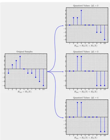
n=1 XnLm i=(n−1)Lm+1 Pi PnLm i=(n−1)Lm+1Pi log |X | Y i=1 PPi i (16) The fact that α∆L is less than 1 is a consequence of the mathematical inequality shown in 17. This proves that quan-tisation will always reduce entropy of the original sequence, with the ratio of the original entropy to the quantised entropy being 1 :α∆L.(n1+...+nM) log(n1+...+nM)< n1logn1+...+nMlognM (17) To illustrate this point, a graphical representation of this phenomenon is shown in figure 5. Figure 5 shows a sequence of integers in the range[−4,4]and graphs that result from the quantisation of the sequence with∆L={2,3,4}. From the graphs it is clear to see how using large quantisation intervals is detrimental to security as the entropy and hence the sequence variability of quantised signal is dramatically reduced.
The linear received signal power is log-normally distributed [22] and so its discrete form can be approximated by the log binomial distribution [23]. The probability distributionp(x=
i) = Pi in the case when the RSS is what we are sampling can thus be expressed as follows:
Pi= n i pi(1−p)n−i (18) where n=Number of RSS samples (19) σ=Standard Deviation=pnp(1−p) (20) The standard deviation (σ) varies depending on the exact wireless communication environment but empirical studies have estimatedσto be in the range of 5 to 12dB depending
1 2 3 4 5 6 7 8 9 10 −4 −3 −2 −1 0 1 2 3 1 2 3 4 5 6 7 8 9 10 −4 −3 −2 −1 0 1 2 3 4 1 2 3 4 5 6 7 8 9 10 −3 −2 −1 0 1 2 3 1 2 3 4 5 6 7 8 9 10 −4 −3 −2 −1 0 1 2 3 4 Original Samples Quantised Values:∆L= 2 Quantised Values:∆L= 3 Quantised Values:∆L= 4 H∆L=H1(X) H∆L=H2(X)< H1(X) H∆L=H3(X)< H2(X) H∆L=H4(X)< H3(X)
FIGURE 5. Figure showing how the quantisation level∆Laffects entropy.
on the environment [24].
The analysis above shows that iterative quantisation will negatively affect entropy with increasing∆L, with the rate at which entropy degrades not only being a function of∆L
but also dependent on the actual probability distribution of RSS values. This is in contrast to ECC based reconciliation which forces nodenbobto reconcile its key to the original key measured by nodenaliceand so does not necessarily reduce the entropy of the key in the reconcilement stage.
B. RANDOMNESS TESTING
In order for keys to be used for cryptographic processes it must be ensured that the generated keys have properties of randomness. The randomness of the generated keys was tested using the discrete frequency spectrum test, which is a part of a standardised cryptographic randomness test [25]. The spectral test works by taking the discrete fourier trans-form (DFT) of a bit stream and testing if the spectrum is sim-ilar with the spectrum that would be obtained from a perfect true randomness source. If a sequence is truly random, then its spectrum will approximately be flat because there will be no dominant frequency components. In addition to this, if a spectrum is random, then 95% of the frequency domain sam-ples will be less than a thresholdT whereT =pnlog(20)
andnis the length of the sequence. The test works by first
FIGURE 6. Graph showing the spectrum of the key sequence and the location
of the 95% threshold.
calculatingNr, the mean number of samples in the spectrum that would be belowT in a truly random sequence andNs, the number of samples in the spectrum that are belowTin the sequence under test. The probability that the sequence under test is truly random is then calculated using the deviation of
Ns fromNr. If that probability is over 99%, then sequence under test is deemed to be random [25]. The test proceeds as follows: KeyStream={k0kk1k...kkNk−1}=x={0,1} n⇔ {−1,1}n (21) X =DFT(x) = n X k=1 xe(j2π(k−1)/n)= n X k=1 f(k) (22) p-value= 1−erf |d| √ 2 (23) where j=√−1 (24)
Nk =(Number Of Keys Under Test) (25)
n=Nk×(Number Of Bits Per Key) (26)
d=pNr−Ns 0.05Ns/2 (27) Nr= 0.95×n (28) Ns= n X k=1 ( 1 |f(k)|< T 0 |f(k)|> T (29) erf(u) = 1 2π Z u 0 e−t2dt (30) A small p-value indicates strong evidence against our null hypothesis (our null hypothesis is that the sequence under test
is random). The NIST standard advises to accept a sequence with a p-value greater than 0.01 as being random [25]. In order to test randomness, 75 different keys were computed and used to form a bit sequence of length 2400 bits. The sequence was then tested using the spectral test. The obtained spectrum can be seen in figure 6. The resultant p-value of the tested bit stream was 0.589 which means the sequence has randomness properties.
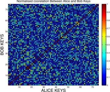
The keys were also tested to see if they are well correlated in a static environment. In this test, 75 keys were computed with a key refreshment period of one minute. For each key, the correlation between itself and each of the other keys was computed and the result plotted on the heat map shown in figure 7. The correlation coefficient between two keys is obtained by computing the cross correlation between the keys and then taking the maximum correlation coefficient (CC) from the resultant vector (this can be seen in 31). From figure 7 it is clear that different keys do not correlate highly with each other between sessions on the vast majority of occa-sions. The points in the map are keys which were generated by legitimate partiesnaliceandnbobin the same session. Out of all key correlations, there is only one rare occassion when subsequent generated keys correlated highly and only one other case of high correlation between key number 4 and key number 9. These relatively rare high correlations could have been caused by channel conditions not changing adequately enough between key generation intervals.
keyA=x={0,1}n⇔ {−1,1}n keyB=y={0,1}n⇔ {−1,1}n CC=|ρxy| (31) where ρxy= E[xy]−E[x]E[y] p E[x2]−[E[x]]2p E[y2]−[E[y]]2 (32)
C. SECURITY ANALYSIS AGAINST COMMON ATTACKS
It is also important to evaluate the security of the scheme in order to understand the additional security benefits that our scheme brings in relation to existing key refreshment and generation schemes. The biggest threat facing sensor networks is arguably brought about by the fairly recent drive to connect them to the internet to create what is known as the internet of things (IoT). Connecting devices in this way leaves WSNs (which can have indirect access to the internet via sinks / base stations) vulnerable to a wide range of attacks from remote users who have access to much more powerful computational resources.
It is important that we make sure that if the key material that was originally deployed with the WSN and/or key material used in a particular session is compromised by a remote user, that user can not use that information to discover any key
10 20 30 40 50 60 70 10 20 30 40 50 60 70 ALICE KEYS BOB KEYS
Normalised coorelation Between Alice and Bob Keys
0 0.1 0.2 0.3 0.4 0.5 0.6 0.7 0.8 0.9 1
FIGURE 7. Correlation Coefficients between Keys (only keys with the same index should correlate highly).
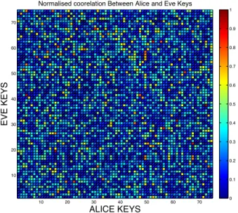
material used in any other session. In other words, we want our scheme to achieve perfect forward and backward security. A type of attack that WSNs are particularly vulnerable to are man-in-the-middle (MITM) attacks. The most direct way an adversary could try and compromise the process is by trying to snoop on communications betweennaliceandnbob and then running going through the key generation process to generate a key. Tests were done with a third node, neve, being a distance of 2m away fromnbob.naliceandnbobwent through the key generation process 75 times withnevealso trying to generate a key from messages sent fromnalice. The correlation coefficient of the keys obtained from nbob and
neveare shown in figure 8. From the figure it is clear that the correlation between keys generated atnaliceandnevewas not high, showing that this scheme can be used even in relatively dense WSN deployments.
The case outlined above is the case where neve is passive. In an active case,nevewill try and inject/broadcast tonalice and/ornbob. In this case, allowing only packets that have been appended with a message authentication code (MAC) to be used in the key reconciliation process will prevent malicious packets from being injected by neve. In the event thatneve tries to influence the wireless environment by flooding the channel with malicious packets and in so doing raising the RSS of received packets received in particular time intervals,
nalice and nbob need to monitor the quality of the link between them by looking at the link quality indicator. An increase in RSS should correspond to an increase in LQI, so any inverse relationship between RSS and LQI will indicate some possible malicious activity.
There is also the possibility of an adversary trying to disrupt the process by jamming the wireless channel. This could be
This article has been accepted for publication in a future issue of this journal, but has not been fully edited. Content may change prior to final publication. Citation information: DOI 10.1109/ACCESS.2018.2806423, IEEE Access
Moara-Nkweet al.: Preparation of Papers for IEEE TRANSACTIONS and JOURNALS
10 20 30 40 50 60 70 10 20 30 40 50 60 70 ALICE KEYS EVE KEYS
Normalised coorelation Between Alice and Eve Keys
0 0.1 0.2 0.3 0.4 0.5 0.6 0.7 0.8 0.9 1
FIGURE 8. Correlation Coefficients between Legitimate and Adversary Keys, D = 2m.
done in two ways, i) the jammer might just jam the particular 802.15.4 channel being transmitted on by transmitting high power noise or ii) the attacker could flood the channel with 802.15.4 compliant packets. In the first case the 2.4GHz 802.15.4 PHY layer provides an inbuilt defence for this using direct sequence spread spectrum (DSSS) technology. DSSS works by encoding the bits to be sent with another pseudo random spreading bit sequence of a substantially higher data rate than the data sequence and then transmitting the result instead of transmitting the bits directly. Doing this has the effect of spreading the information sent over a large bandwidth and in so doing preventing narrowband indiscriminate jammers.
In the event of an adversary flooding the channel with 802.15.4 compliant packets, the use of DSSS will not prevent the attack. Relying on the MAC only will not prevent the attack as each malicious packet will need to be received, leading to denial of service. In this case of the attack, actions need to be taken at the physical layer to minimise the impact. When the PHY layer transmits a packet, it prepends the packet with a synchronisation (SYNC) header. The header does not contain any application specific information, it is used to make sure the transceiver’s communicating can synchronise before the actual packet information starts. The SYNC header used in the CC2420 is shown in Fig 9. In order to minimise the impact of flooding attacks, legit-imate parties could switch from the default 802.15.4 syn-chronisation header value of 0x00007A and use a different header unique value on a per packet basis when generating keys. A unique SYNC header value will prevent flooding attacks because packet information (e.g destination address, packet length etc.) will not even be read if the expected SYNC header preamble and received SYNC header preamble
SWRS041c Page 37 of 85
In reception, CC2420 synchronises to
received zero-symbols and searches for the SFD sequence defined by the
SYNCWORD register. The least significant
symbols in SYNCWORD set to 0xF will be
ignored, while symbols different from 0xF will be required for synchronisation. The default setting of 0xA70F thereby requires
one additional zero-symbol for
synchronisation. This will reduce the number of false frames detected due to noise.
The following illustrates how the
programmed synch word is interpreted
during reception by CC2420: If SYNCWORD =
0xA7FF, CC2420 will require the incoming
symbol sequence of (from left to right) 0 7
(from left to right) 0 0 7 A. If SYNCWORD =
0xA700, CC2420 will require the incoming
symbol sequence of (from left to right) 0 0 0 7 A.
In receive mode CC2420 uses the
preamble sequence for symbol
synchronisation and frequency offset adjustments. The SFD is used for byte synchronisation, and is not part of the data stored in the receive buffer (RXFIFO).
0 7 A
IEEE 802.15.4
Preamble SFD
CC2420 2·(PREAMBLE_LENGTH + 1) zero symbols
0 0 0 0 0 0 0 SW0 SW0 =SYNCWORD[3:0] SW1 =SYNCWORD[7:4] SW2 =SYNCWORD[11:8] SW3 =SYNCWORD[15:12] SW1 SW2 SW3
if different from 'F', else '0' if different from 'F', else '0' if different from 'F', else '0' if different from 'F', else '0'
Synchronisation Header
Each box corresponds to 4 bits. Hence the preamble corresponds to 8 x 4 ''0' s or 4 bytes with the value 0.
Figure 18. Transmitted Synchronisation Header
16.2 Length field
The frame length field shown in Figure 17 defines the number of bytes in the MPDU. Note that the length field does not include the length field itself. It does however
include the FCS (Frame Check
Sequence), even if this is inserted
automatically by CC2420 hardware. It also
includes the MIC if authentication is used. The length field is 7 bits and has a maximum value of 127. The most significant bit in the length field is reserved [1], and should be set to zero.
CC2420 uses the length field both for transmission and reception, so this field must always be included. In transmit mode, the length field is used for underflow detection, as described in the FIFO access section on page 31.
16.3 MAC protocol data unit
The FCF, data sequence number and address information follows the length field as shown in Figure 17. Together with the MAC data payload and Frame Check Sequence, they form the MAC Protocol Data Unit (MPDU).
The format of the FCF is shown in Figure 19. Please refer to [1] for details.
FIGURE 9. Synchronisation Header (Source [17]).
differ by more than a set threshold of bits (this threshold is configurable on the transceiver). The SYNC value is sent as plaintext and so would need to change synchronously on a per packet basis in order to foil attacks from sophisticated denial of service attackers who are snooping on SYNC headers and also flooding at the same time.
We now consider another attack scenario where the current session key is Kj and an adversary compromises the key material from a previous session Ki. If we had just hashed the key (together with other deterministic information) when moving to new sessions in order to refresh keys, as is the case with current WSN deployments, then session keys that were used before Ki would not be computable because a hash is irreversible but all session keys that come afterKi (including Kj) could be easily computed fromKi by just applying successive hashes. This is a major problem because if any time in the future the original key materialK0that the
WSN was deployed with is compromised, then all the session keys that have ever been used would be at risk. If, on the other hand, our proposed scheme is used, then the compromise of any session key will not compromise any other session key as the adversary will not be able to evaluate the physical layer values that were used to refresh session keys. This is because the adversary would have no access to the values offi in 8. A big advantage of a PL-SKG scheme is that an adversary who has not been locally there throughout the entire lifespan of the WSN network will find it very difficult to compromise a key, even if they know all the key information loaded on nodes at deployment.
X. CONCLUSION AND FURTHER WORK
This paper has discussed and highlighted the key challenges that are faced when trying to design and implement PL-SKG schemes on WSNs. We have shown that there still exist opportunities to increase the key generation rates of current schemes by exploiting the fading characteristics of chips over communication channels. We have also proposed a novel PL-SKG scheme and implemented it on real nodes enabling two parties to generate and refresh pair-wise keys. Experiments have shown that the proposed PL-SKG scheme has a high key agreement rate and that the generated key decorrelates quickly with respect to distance.
The proposed PL-SKG scheme in this paper is suitable for use in static channels. The scheme uses filtering and ECCs to generate and refresh cryptographic keys using RSS
surements. Privacy amplification is carried out in a manner that ensures both perfect forward and backward security. Thus any compromised session key material (including all the initial key information the nodes were deployed with) does not compromise key material in any other session. This paper also analyses the security of the both state-of-the-art PL-SKG schemes and our proposed scheme and proves that the existing iterative quantisation used for key reconciliation purposes reduces key entropy. Further security analysis against a variety of attack vectors was also carried out to highlight the strengths and weaknesses of our PL-SKG scheme, and proposals of practical measures that help prevent and/or mitigate the effects of these attacks on a WSN network were put forward. Further work could be done to incorporate the key generation and refreshment capabilities of the proposed scheme in full key recovery protocols.
REFERENCES
[1] F. Xhafa, F. Leu, and L. Hung, Smart Sensors Networks: Communication Technologies and Intelligent Applications, ser. Intelligent Data-Centric Systems: Sensor Collected Intelligence. Elsevier Science, 2017. [2] A. Forster, What are Wireless Sensor Networks? Wiley-IEEE Press, 2016,
p. 186.
[3] A. Liu and P. Ning, “Tinyecc: A configurable library for elliptic curve cryptography in wireless sensor networks,” in 2008 International Confer-ence on Information Processing in Sensor Networks (ipsn 2008), April 2008, pp. 245–256.
[4] M. Wilhelm, I. Martinovic, and J. B. Schmitt, “Secure key generation in sensor networks based on frequency-selective channels,” IEEE Journal on Selected Areas in Communications, vol. 31, no. 9, pp. 1779–1790, September 2013.
[5] J. Zhang, T. Q. Duong, R. F. Woods, and A. J. Marshall, “Securing wireless communications of the internet of things from the physical layer, an overview,” CoRR, vol. abs/1708.05124, 2017. [Online]. Available: http://arxiv.org/abs/1708.05124
[6] C. Sahin, B. Katz, and K. R. Dandekar, “Secure and robust symmetric key generation using physical layer techniques under various wireless environments,” in 2016 IEEE Radio and Wireless Symposium (RWS), Jan 2016, pp. 211–214.
[7] S. Mathur, W. Trappe, N. Mandayam, C. Ye, and A. Reznik, “Radio-telepathy: Extracting a secret key from an unauthenticated wireless channel,” in Proceedings of the 14th ACM International Conference on Mobile Computing and Networking, ser. MobiCom ’08. New York, NY, USA: ACM, 2008, pp. 128–139. [Online]. Available: http://doi.acm.org/10.1145/1409944.1409960
[8] K. Kaemarungsi and P. Krishnamurthy, “Modeling of indoor positioning systems based on location fingerprinting,” in IEEE INFOCOM 2004, vol. 2, March 2004, pp. 1012–1022 vol.2.
[9] K. Zeng, “Physical layer key generation in wireless networks: challenges and opportunities,” IEEE Communications Magazine, vol. 53, no. 6, pp. 33–39, June 2015.
[10] H. Liu, J. Yang, Y. Wang, and Y. Chen, “Collaborative secret key extrac-tion leveraging received signal strength in mobile wireless networks,” in INFOCOM, 2012 Proceedings IEEE, March 2012, pp. 927–935. [11] F. Zhan and N. Yao, “On the using of discrete wavelet transform
for physical layer key generation,” Ad Hoc Networks, vol. 64, no. Supplement C, pp. 22 – 31, 2017. [Online]. Available: http://www.sciencedirect.com/science/article/pii/S157087051730104X [12] T. Aono, K. Higuchi, T. Ohira, B. Komiyama, and H. Sasaoka, “Wireless
secret key generation exploiting reactance-domain scalar response of mul-tipath fading channels,” IEEE Transactions on Antennas and Propagation, vol. 53, no. 11, pp. 3776–3784, Nov 2005.
[13] G. Revadigar, C. Javali, H. J. Asghar, K. B. Rasmussen, and S. Jha, “Mobility independent secret key generation for wearable healthcare devices,” in 10th EAI International Conference on Body Area Networks, BODYNETS 2015, Sydney, Australia, September 28-30, 2015, 2015. [Online]. Available: http://dx.doi.org/10.4108/eai.28-9-2015.2261446
[14] Y. Liu, H. H. Chen, and L. Wang, “Physical layer security for next generation wireless networks: Theories, technologies, and challenges,” IEEE Communications Surveys Tutorials, vol. 19, no. 1, pp. 347–376, Firstquarter 2017.
[15] X. Zhou, L. Song, and Y. Zhang, Physical Layer Security in Wireless Communications. CRC Press, 2014.
[16] X. Wang, L. Jin, K. Huang, M. Li, and Y. Ming, “Physical layer secret key capacity using correlated wireless channel samples,” in 2016 IEEE Global Communications Conference (GLOBECOM), Dec 2016, pp. 1–6. [17] CC2420: 2.4 GHz IEEE 802.15.4 / ZigBee-ready RF Transceiver, Texas
Instruments, 2013, sWRS04c.
[18] M. Schwartz, Mobile Wireless Communications. Cam-bridge University Press, 2005. [Online]. Available: https://books.google.co.uk/books?id=rAiyyKM9ppoC
[19] K. Zhang, Wireless Communications: Principles, The-ory and Methodology. Wiley, 2015. [Online]. Available: https://books.google.co.uk/books?id=GGXKCQAAQBAJ
[20] P. Medina, J. R. Gallardo, J. Sanchez, and F. Ramarez-Mireles, “Impact of Delay Spread on IEEE 802.15.4a Networks with Energy Detection Receivers,” Journal of applied research and technology, vol. 8, pp. 352 – 362, 12 2010.
[21] D. Gay, P. Levis, R. Von Behren, M. Welsh, E. Brewer, and D. Culler, “The nesc language: A holistic approach to networked embedded systems,” in Acm Sigplan Notices, vol. 38, no. 5. ACM, 2003, pp. 1–11.
[22] X. Yin and X. Cheng, Propagation Channel Characterization, Parameter Estimation, and Modeling for Wireless Communications, ser. Wiley - IEEE. Wiley, 2016. [Online]. Available: https://books.google.co.uk/books?id=IRWuDQAAQBAJ
[23] F. Gravetter and L. Wallnau, Statistics for The Behav-ioral Sciences. Cengage Learning, 2016. [Online]. Available: https://books.google.co.uk/books?id=ZCNTCwAAQBAJ
[24] H. Anderson, Fixed Broadband Wireless Sys-tem Design. Wiley, 2003. [Online]. Available: https://books.google.co.uk/books?id=M8NOGnp2IRwC
[25] A. Rukhin, J. Soto, J. Nechvatal, M. Smid, and E. Barker, “A statistical test suite for random and pseudorandom number generators for cryptographic applications,” Booz-Allen and Hamilton Inc Mclean Va, Tech. Rep., 2001.
KEMEDI MOARA-NKWE joined Liverpool John Moores University (LJMU) in 2015 as a researcher in Network Security within the LJMU PROTECT research center. He has an MEng degree in Electronics with Wireless Communications which he obtained in 2015. His main research interests are in Network Security, IoT/WSN security, cryptography and Physical layer security.
QI SHIis a Professor in Computer Security, Head of Department Research, and Director of the PROTECT Research Centre in the Department of Computer Science at Liverpool John Moores University (LJMU) in the UK. He received his PhD in Computing from the Dalian University of Technology, P.R. China. He then worked as a Research Associate on an EU Research Project at the University of York in the UK. After the project, Prof Shi joined LJMU, working as a Lecturer and then a Reader before becoming a Professor. He has many years research experience in a number of security related areas, e.g. sensor network security, secure service composition, privacy-preserving data aggregation, cryptography, blockchain, intrusion detection, computer forensics, formal security models and cloud security. He has published over 200 papers in international conference proceedings and journals, and served for a number of conference IPCs and journal editorial boards. He has also played a key role in many research and development projects such as the EU-funded Aniketos and Wi-5 projects.
GYU MYOUNG LEE joined the Liverpool John Moores University (LJMU), UK in 2014, as a Senior Lecture in the department of Computer Science and was promoted to a Reader in 2017. He is also with KAIST Institute for IT convergence, Daejeon, Rep. of Korea, as an Adjunct Pro-fessor from 2012. Before joining the LJMU, he worked with the Institut Mines-Telecom, Telecom SudParis from 2008. Until 2012, he was invited to work with the Electronics and Telecommunications Research Institute (ETRI), Rep. of Korea. He worked as a research professor in KAIST, Rep. of Korea and as a guest researcher in National Institute of Standards and Technology (NIST), USA, in 2007. He worked as a visiting researcher in the University of Melbourne, Australia, in 2002. Furthermore, he also has work experience in industries in Rep. of Korea. His research interests include Internet of Things, Web of Things, computational trust, knowledge centric networking and services considering all vertical services, Smart Grid, energy saving networks, cloud-based big data analytics platform and multimedia networking and services. He is a Senior Member of IEEE.
MAHMOUD HASHEM EIZAis a Lecturer in Computing (Computer and Network Security) at the School of Physical Sciences and Computing, Uni-versity of Central Lancashire. Prior to that, he was a researcher in network security and privacy in the Department of Computer Science at Liverpool John Moores University (LJMU). His research interests include computer, communication, and network security, with specific interests in quality-of-service and wireless network security and privacy in Vehicular Networks, Smart Grids, Cloud Computing, and Internet of Things. Throughout his roles, he has been significantly involved in the preparation and writing of numerous research grant proposals including H2020 and InnovateUK. Be-sides that, he is currently involved in the research activities of the EU-funded Wi-5 project. Mahmoud has published a number of papers in prestigious IEEE conferences and journals and has served in the committees of several prestigious IEEE conferences and workshops such as IEEE GLOBECOM and IEEE CCNC.