A LOCAL POSITIONING SYSTEM FOR AGV NAVIGATION
A thesis presented to the faculty of the Graduate School of
Western Carolina University in partial fulfillment of the
requirements for the degree of Master of Science in Technology
By
Kenyatta Fortune
Advisor: Dr. Peter Tay
Associate Professor of Engineering & Technology
Committee:
Dr. Adams, Engineering & Technology
Dr. Yanik, Engineering & Technology
iii TABLE OF CONTENTS LIST OF TABLE ... iv LIST OF FIGURES ...v ABSTRACT ... vi CHAPTER 1: INTRODUCTION ...7
CHAPTER 2: LITERATURE REVIEW ...14
2.1 Introduction ...14 2.2 Current Techniques ...15 2.3 Possible Techniques ...17 CHAPTER 3: METHODOLOGY ...18 3.1Development Plan ...18 3.2Schedule ...18
3.3 Experimental Design Process ...19
3.4Procedure for Testing and Collecting Data ...20
CHAPTER 4: RESULTS ...23
CHAPTER 5: FUTURE WORK ...27
CHAPTER 6: CONCLUSION ...29
BIBLIOGRAPHY ...33
iv
LIST OF TABLE
v
LIST OF FIGURES
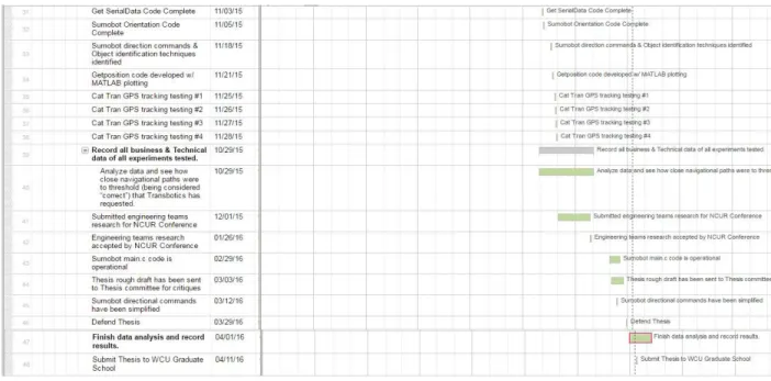
Figure 1: Gantt chart ...13
Figure 2 : Shown above is the Cat Tran GPS latitude and longitude route coordinates ...25
Figure 3: Shown above is Multiple Cat Tran GPS latitude and longitude route coordinates ...25
Figure 4: Degree thresholds interpolated by a second order polynomial ...26
Figure 5: The proposed summer internship optimal rate ...30
Figure 6: The proposed summer internship economic rate ...31
vi
ABSTRACT
A LOCAL POSITIONING SYSTEM FOR AGV NAVIGATION
Kenyatta Fortune, Master of Science in Technology Western Carolina University (March 29, 2016) Director: Dr. Peter Tay
Automated guided vehicles (AGVs) are mobile robots that are generally used for mundane tasks like moving pallets or containers, assembly line processes, sorting, etc. in warehouses and
manufacturing facilities. Transbotics, Inc. (seehttp://www.transbotics.com/) located in Charlotte, North Carolina is a regional company that is a leading manufacturer of AGV for industrial and manufacturing applications. The navigation of the Transbotics AGVs are accomplished by following lines painted on the floor or an infrared (IR) triangulation positioning system. Line followers are vulnerable to detection errors, even in ideal conditions, and IR triangulation positioning systems require fiduciary IR reflective antennas. These navigation systems are strictly limited to indoor use. Outdoor AGV navigation is problematic with the Transbotics AGVs. My research will propose a solution to this obstacle by developing a global positioning system (GPS) navigation system. This positioning system will be designed so that it can be retrofitted to any Transbotics AGV. The retrofitting aspect is important in that the existing Transbotics AGVs will not have to be modified or the AGV parts specification will not have to change. The positioning system will allow the AGVs to operate either indoors or outdoors
vii
this research to Transbotics are enormous in that they will be able to offer this positioning system to current, past, and future Transbotics’ customers as an upgrade to their existing Transbotics AGVs.
7
CHAPTER 1: INTRODUCTION
Automated guided vehicles (AGVs) are mobile robots used for tasks like moving pallets or containers, assembly line processes, sorting, etc. in warehouses and manufacturing facilities. AGVs are known to consist of assembly line, conveyor vehicles, custom engineered AGV vehicles, heavy load transport, fork lift and roll handling vehicles, and tuggers. One company in particular that has much knowledge and experience with the development, design, and testing of these types of AGVs is Transbotics. Transbotics is a manufacturer that specializes in AGV technology, ranging from the infant stages of exterior design specifications to the final stages consisting of imbedded automation integration.
After the AGV has been built to a customer’s satisfaction, Transbotics fully supports the installation process by helping incorporate the new AGV system to specific tasks. Transbotics is most well-known for two types of systems used within its AGV product line. One type is the line guided followers for vehicles such as pallet movers and other autonomous guided carts better known as AGCs. These are vehicles that follow specific tape or painted strips on the floor which creates routes for the AGCs to follow [1]. The second type of system used by Transbotics is an infrared (IR) triangulation positioning system, which allows Transbotics AGVs to pinpoint its position in real time by using cylindrical reflectors that are set up within the area that these machines will be used for much more challenging tasks [5].
Transbotics has fully developed a robust system for the control of their AGVs for indoor uses. Outside usage seems to be a problem for Transbotics since their current systems of control, such as line followers are vulnerable to detection errors, even in ideal conditions, and IR
8
weather conditions can adversely effect performance. These complications make Transbotics unfortunately dependent on indoor use. After researching the Transbotics AGV business model and customer’s pain points (or needs), I have proposed a GPS and video tracking navigation system that would allow all their AGVs to be capable of outside applications.
The economic impact of this research to Transbotics is enormous in that they will be able to offer a new AGV which Transbotics has never manufactured before. This technology would allow them to double their target market and increase their company value by allowing them to expand into a new part of the AGV market. This technology also allows Transbotics to retrofit past models allowing to further capitalize on all the models in their product lifecycles. The retrofitting aspect is important in that the existing Transbotics AGVs will not have to be modified or the AGV parts specification will not have to change. The positioning system will allow the AGVs to operate either indoors or outdoors without the need for lines painted on the floor or fiduciary antennas.
An integral part of this thesis project was to manage the technological development and work of a team of four engineering students in three core phases of research, development, and testing. The tasks were local positioning, orientation, and object identification. The four
engineering students assisted in the development and testing stages of the thesis by means of completing honors contracts within the WCU Honors College and ET 480 Independent Studies with Dr. Peter Tay. The four engineering and technology students’ contributions were
recognized and presented in the North Carolinas Undergraduate Research Conference (NCUR), which was hosted at UNC Asheville on April 7-9, 2016. The four engineering and technology students who made technical contributions are Steven “Kyle” Johnson, Wes Dixon, Taylor Parks, and Chase Weddle.
9
Steven “Kyle” Johnson, is a sophomore undergraduate student, majoring in electrical engineering. His task was to develop a code that can parse GPS longitude and latitude coordinates from a commercially available GPS module. This acquired data is later used to create a sequence of Cartesian (X,Y) coordinate points and displaying the GPS coordinates (longitude and latitude). The path of the WCU Cat Tran shuttle as it navigates through the WCU campus was used to test the reliability of Kyle’s Matlab code.
Wesley Dixon, is a senior undergraduate student, majoring in electrical & computer engineering technology. His tasks focused on determining the orientation, the direction the AGV or robot, is facing. Wesley’s code determines the robot orientation from two distinct GPS coordinate points.
Taylor Parks, is a sophomore undergraduate student, majoring in electrical engineering. His research topic was to identify objects, using image processing techniques that can be
integrated to autonomously find objects like hitches for the AGV to pull or push. This aspect of the project remains did not result in any fruitful contributions and is left for future work.
Chase Weddle, is a senior undergraduate student, majoring in electrical & computer engineering technology. His task was to develop controls for the test robot, a sumo-bot, which was the project’s primary testing platform.
The management of these engineering students required directing and utilizing resources to achieve the organizational goals and expectations of Transbotics. Within my management role the goal was to achieve a competitive advantage for the client Transbotics by setting goals, making plans, motivating and mobilizing people, gathering and distributing resources, and monitoring and assessing objectives. I had to continually provide the necessary support from the bottom up, and also provide top down oversight from initial idea stages to final development
10
plans. The level of responsibility that came with the management of this project would have been classified in three levels of management, low, medium and high. All levels of management are represented in the Gantt chart in Figure 1.
The low management responsibilities consisted of managing work that is closer to colleagues and building bonds, while being a part of team as well as management. I had to make sure that individual engineers are meeting their performance goals in a way that aligns with the organizational goals, such as completing a set number of projects by a specific deadline or doing a set number of experiments within a certain period of time.
The medium management responsibilities consisted of report to top management of Transbotics, such as the Head of Transbotics Research and Development Division, and serve as the head of major development plans for the four student engineering team and utilize their specialized skills.
The high management responsibilities consisted of setting the overall direction of the team and making sure that major organizational objectives were achieved. The ability to speak one on one with high executives within Transbotics, such as the Transbotics Chief Executive Officer, gave insight into their industry and the interworking’s of their company.
Through this experience, I was able to attract an external business into the WCU region, which is now collaborating with me and Dr. Peter Tay. I am proud as a student to be able to support WCU’s 20/20 Vision initiative, by drawing in companies that wish to look for new emerging engineering or otherwise talent on our campus.
11
The following email from Alex Alesna and Dr. Tay is confirmation of Transbotics commitment to this engagement project.
Date: 10/28/2014 Time: 12:35pm
That is completely fine. Thank you for the information and we look forward to meeting with your head of electrical and R&D.
Note: After the Tour we were able to figure out a way to have a positive impact on Transbotics and stayed in contact with Mr. Alesna
Hello Peter,
Thank you for taking your time to come and visit us here in Charlotte. I know it's a long drive for you guys. I hope you, Kenyatta and Kyle had a pleasant trip home.
I apologize for the slow response of this email. I was trying to get feedback from all of our key people but as you know we as so swamped with finishing up the projects we currently have. I have shown your video to Claude, Jim and Kevin and we all were very impressed with the guidance and accuracy of your robot. We believe that there's great potential for us to incorporate your controls architecture. Mr. Lennart Johansson, our VP of R&D, was out all week but he should be back next week. I will be presenting your video to him in our next R&D meeting and hopefully get his buy in. Then we can be discussing best step moving forward.
In the meantime, please let me know if you have any questions for me. Kind Regards,
Alex Alesna
Sr. Electrical Engineer
TRANSBOTICS CORPORATION An ISO 9001:2008 Registered Company 3400 Latrobe Drive. Charlotte, NC. 28211 Tel 704-206-7029. 704-362-1115
Fax 704-364-4039
Visit us on the Web at www.transbotics.com
From the in person, email, and telephone correspondences with Transbotics’ Executives, it was agreed that the constraints of the proposed navigation system should adhere to:
1. Must be a portable local position system.
2. Must be able to easily attach and/or detach to Transbotics AGV. 3. Must have an accuracy of within at least ±10 millimeters.
13 Figure 1: Gantt chart
14
CHAPTER 2: LITERATURE REVIEW
2.1 Introduction
Automated guided vehicles also known as AGVs can be described simply as robots with the power of mobility. AGVs are developed and used for a large assortment of tasks and duties that are critical for large and small companies. AGVs are used in areas such as warehouses and manufacturing facilities, moving and delivering resources to the designated areas. One company in particular that has much knowledge and experience with the development, design, and testing of AGVs is Transbotics. Transbotics is a manufacturer that specializes in AGV technology that range from the infant stages of exterior design specifications to the final stages consisting of embedded automation integration [2].
After the AGV has been built to a customer’s satisfaction Transbotics fully supports the installation process by assisting in the implementation of the new AGV system to a specific task. Transbotics is most well-known for two types of systems within its AGV product line. One type is the line guided follower for vehicles such as pallet movers and other autonomous guided carts (AGC). These are vehicles that follow specific tape or painted strips on the floor to create routes for the AGCs to follow [1]. The second type of system used by Transbotics is an infrared (IR) triangulation positioning system, which allows Transbotics AGVs to pinpoint its position in real time. The IR system requires cylindrical reflectors that are set up within an enclosed area.
Transbotics has fully developed a robust system for the control of their AGVs for indoor uses. But outside usage is an issue for Transbotics since their current systems of control, such as line followers are vulnerable to detection errors, even in ideal conditions, and IR triangulation positioning systems require fiduciary IR reflective antennas within a well regulated environment.
15
These constraints make Transbotics limited to indoor use. My research presents a solution to this obstacle by developing a global positioning system (GPS). The proposed position system will be made so that the system can be retrofitted to any Transbotics AGV.
The retrofitting aspect is important in that the existing Transbotics AGVs will not have to be modified or the AGV parts specification will not have to change. The positioning system will allow the AGVs to operate either indoors or outdoors without the need for lines on the floor or fiduciary antennas. The economic advantages of this research to Transbotics are enormous in that they will be able to offer an AGV which no other AGV manufacturer can offer. Furthermore this positioning system can be offered to current, past, or future Transbotics’ customers as an upgrade to their existing Transbotics AGV. More general, this positioning system can be used by any vehicle to establish local position and provide navigation.
2.2 Current Techniques
The first technique identified that has been used for control of AGVs is the use of guide tape. This type of control is well known for navigating smaller automated vehicles, better known as autonomous guided carts (AGCs). The AGCs carefully follow the corresponding tape that is laid out by using an appropriate line detection. A great asset to using guided tape is that it’s relatively inexpensive and low maintenance in both applying to floor surfaces and even remapping specific areas. Color tape is more cost efficient compared to magnetic tape, yet its disadvantage lies within dealing with frequent heavy traffic within an area. The result of frequent traffic can quickly lead to the guide tape to become damaged or cause sensor readings to go awry due to the accumulation of dirt covering the tape. Magnetic guided tape is made up of a flexible magnetic strip with dual polarity. [1,4].
16
The second technique that is implemented when using AGVs are laser target navigation. Laser navigation is accomplished by setting up reflective tape or antennas on different surfaces such as fixed apparatuses, poles, and walls. AGVs typically have a receiver and transmitter incorporated somewhere on the vehicle. This device also has the capacity to rotate to receive the dimensions of the targeted area and to constantly transmitting back current positioning signals. Angles and even distances can be calculated by reflectors that are currently in range of the receiver. Reflectors are used to map the area and add to preexisting mapping with the AGV memory. Thus allows the AGV to be able to triangulate its exact position. The direction is constantly adjusted helping it to avoid possible barriers and stay on route. [2,4]
There are two specific types of lasers known within the laser navigation community. The first one is a pulsing laser that scans by sending out a laser light. At 8 scanned revolutions, pulsed lasers can send laser light at the pulse rate of 14.4 kHz, which can produce resolution up to approximately 3.5 milli-radians (mrad) or 0.2 degrees. For pulse laser readings to properly guide the vehicle the data must be interpolated by the incoming reflected laser light, which locates the center of the reflector [6].
The second specific type is modulated laser. One difference between modulated lasers and pulsed lasers is that modulated have a greater range and a better improved accuracy reading. By sending constant laser light, modulated lasers can have continual reflection which is allowed by the scanner quickly receiving feedback from the reflector. These reflections are stopped when arriving at trailing edges of reflectors which helps improve measurements in both consistency and accuracy. Lastly, modulated laser typically to have an angular resolution of approximately 0.1 mrad, equivalently 0.006 degrees, at 8 scanner revolutions per second [6].
17 2.3 Possible Techniques
There are a variety of technologies that can be used to provide support in keeping up with current local positioning as well as assisting systems that uses them. The following will give details of these technology.
A. Accelerometers measure acceleration. A three axis accelerometer provides three output voltages that are proportional to the acceleration in the x, y, and z directions, respectively. [8]. B. Gyro-Scope is a device that uses angular momentum to determine orientation. They are frequently used in inertial navigation systems that cannot use magnetic compasses [7].
C. Optical encoding uses a physical disc with evenly spaced holes or opaque parts in a repetitive pattern. This incorporated with a light component and photo detector will read out an optical pattern that directly corresponds with the movement of the object. Essentially optical encoders can be used to detect current speed. [3].
D. The Global Positioning System (GPS) is a satellite navigation system that provides accurate information like time and location. This space based system can work within any weather conditions and are connected by a cluster of GPS satellites [5].
18
CHAPTER 3: METHODOLOGY
The management and development of the proposed AGV/AGC navigation system are presented in this chapter and fall into planning (project requirements, scheduling, work
breakdown structure), research and development, and system testing. The implementation aspect is beyond the scope of this thesis and left for future consideration.
3.1 Development Plan
I establish a working relationship with Transbotics, which is an Autonomous Guided Vehicle manufacturer, based in Charlotte, NC. It was imperative that I learn about Transbotics present and upcoming AGV/AGC models. Additionally, I became familiar with the strengths and weaknesses each Transbotics AGV/AGC. I researched their business model and customer’s pain points (or needs). Continuous dialogue with Transbotics about logistics and how to tackle foreseeable issues were vital. The final ``selling” point will be to achieve a demo of what could be integrated to the Transbotics AGVs. Moreover, I have identified and shown that AGVs can be utilized in new areas that are no longer restricted by indoor facilities.
3.2 Schedule
The roughly year long project’s timeline, including composition of this thesis, is listed below.
April: I submit my thesis proposal and literature survey.
May-June: I collect required information needed for future experiments. I reviewed parts and resources needed for creating 3D mapping of a targeted terrain in constant real time accuracy. I conducted research into best ways to autonomously control a sumo-bot, the testing platform. I worked on the scope/rescaling of what needed to be accomplished. I worked on developing a
19
business strategy for possible continued project work as well as looking into navigation research methods. I conducted basic experiments on the phase encoding technic, inertia measurement systems (gyroscopes, accelerometers, etc.), and GPS modules. I built a business relationship with Transbotics Chief Executive Officer and Transbotics Research and Development team.
August-September: I looked more closely into the Pros and Cons of the different local
positioning techniques. I revise and/or revisit experiments (if needed) and updated business and technical portfolio, etc. I began extensive testing on the GPS navigational processes. I relayed all research information to Transbotics about having all parameters that they requested established. October-December: I documented all the technical data from all the experiments. I analyze the data and see how closely the navigational paths were to the correct path.
January-February: I finish data analysis and recorded the results. March: I defended my thesis.
April: I finish the project documentation, proposed future work, and completed thesis composition. I expect to demonstrate the proposed GPS navigation system to Transbotics. 3.3 Experimental Design Process
After accessing the overall needs of Transbotics, as well as also understanding what is required on the technical side, a materials list and a plan of procedure was generated. I gather the needed materials for the preparation of the first round of experimentation. The result of the experimentation on efficiency, reliability, and cost of each possible navigation system, the
committee of engineering and technology student team and I discussed the best direction to move forward. My plan was to develop a positioning technology that can be very quickly assimilate into Transbotics already existing systems. I wanting to not only solve their current issues but to
20
utilize what they already have to offer. I based a business and technical portfolio of collaboration with Transbotics.
After figuring out the best navigation positioning system, I repeated the process of performing different experimental versions of the testing and data collection. The experimental results showed accurate latitude and longitude navigational coordinate from the GPS module. This process was repeated to test the GPS navigation for repeatability and reliability. Another test was to choose a particular location, put obstacles within a navigational path to see how well the program is able to correct itself trying to navigate past these objects. All the while, I stayed in contact with Transbotics about all the current techniques tested.
3.4 Procedure for Testing and Collecting Data
The GPS navigation system is capable of accurate information concerning time and location. This space oriented system can work within any weather conditions and is connected by a cluster or network of orbiting GPS satellites. Satellite signals are obtained by GPS receivers, such as navigation devices and are used to calculate the exact position, speed and time of an object’s current location. A GPS receiver uses trilateration (a more complex version of
triangulation) to determine its position on the surface of the earth by timing signals from three satellites in the GPS. Trilateration can be explained as satellites using the process of determining absolute or relative locations of points by measurement of distances, using the geometry of circles, triangles, or spheres to better pinpoint your position on a map knowing the precise distance from three different landmarks by the use of compasses. Depending on where the satellites are focused there overlap will give the exact position of the desired target and also the radius of each circles, triangles, or sphere to know your distance from each landmark.
21
In my project the GPS module is connected to my laptop, which provides power to the GPS module through a USB cable. There is a RS232 serial connection between the GPS module and the laptop. This allows the incoming ASCII coded data to be directly sent over to the
computer at a baud rate of 9600 and easily parsed and ASCII data corresponding to number converted into decimal. The ASCII coded data provides National Marine Electronics Association (NMEA) data, which contains latitude, longitude, time, elevation, and other relevant data. When the module is successfully powered on the GPS module requires direct access to at least three global orbiting satellites to provide valid latitude and longitude information. The GPS module has an initial wait time of ninety seconds before its ready to start outputting the serial stream of ASCII coded NMEA data.
After the appropriate wait time has passed the module immediately sends the proper coordinates of the GPS module’s location every second. This can be confirmed from seeing the indication light that blinks in succession every one second indicating proper syncing with the global positioning satellites. The proper baud rate and com port connection allows the GPS ASCII code to be read into MATLAB. The MATLAB code then parses the (Latitude &
Longitude) ASCII string and converts the latitude, longitude, and time data into decimal values. MATLAB code was developed by Kyle to parse the NMEA data and determine valid latitude and longitude data from the sequence of ASCII string following “GLL” every second. Although more information like elevation, the parts that it Kyle’s code specifically captures from the GLL line are latitude, longitude, N, S, E, W, and real time. All other additional information is voided and is not stored. After all required information has been gathered the next step is for all data points to be stored within a file. All previous mapped areas by the GPS module coordinate points can be stored and later be seen resulting in a digital of plotted latitude and longitude
22
coordinates in MATLAB. The relevant MATLAB codes to acquire the serial stream of NMEA data, parse the GLL line, and produce latitude, longitude, and time in double floating point IEEE 754 format are GetSerialData.m and GetPosition.m. These MATLAB codes are listed in the appendix.
The orientation portion a small sumo-bot was build and connected to the same GPS module used for tracking. The sumo-bot was controlled via Bluetooth from a laptop and essentially functioned as a remote controlled car. The orientation script used the tracking script to acquire and record the position of the sumo-bot, the sumo-bot was then moved in a random direction and stopped then position was acquired and recorded again. Based on the initial and final recorded positions the orientation script could determine where the sumo-bot moved in relation to its initial position. The orientation script was able to carry out this procedure for any number of movements and then determine where the sumo-bot was in relation to the starting point. The early stages of the sumo-bot can be seen in Figure 2 and 3. The robot navigation codes described are the MATLAB gps_orientation.m and robot_main.c. Both gps_orientation.m and robot_main.c are listed in the appendix.
23
CHAPTER 4: RESULTS
The best way to see if this process would work properly was to try it in a real life application. The requirements consisted of mapping a moving object that would allow
continuous recording of new latitude and longitude coordinate locations. The best solution for this method would be the use of the Western Carolina University (WCU) Cat Tran. The WCU Cat Tran is the on-campus shuttle that moves throughout the college from station to station continuously on the same cycle. After spending about 30 minutes initially on the Cat Tran the first round of coordinates were successfully stored and was properly digitized into Figure 2. The latitude and longitude coordinates made it easily recognizable about where exactly the Cat Tran has been. The points lined up precisely where the Cat Tran has been and showed all geographical positions and turns made. WCU students easily recognize major WCU landmarks from just the digitized mapping alone. To check the consistency of the navigational mapping the test was conducted another three times. The results showed majority of the latitude and longitude points initially mapped from the first test becoming overlapped by each of the three test afterwards, though there were some areas that had a few outliers points in Figure 3, overall from all four times the average of all point positions fell approximately within the same locations.
An additional piece of the project was to determine the overall variance or lack of consistency that the GPS tracker provided throughout its accuracy of outputting the proper latitude and longitude coordinates. The best way to look into this issue was to run a series of one hundred stationary point’s, which takes one hundred seconds. After the time cycle is completed the next step is to take all one hundred latitude & longitude points and let MATLAB find the variance from the cumulative average. The overall average of all one hundred latitude and
24
longitude data points was 35.3069 degrees. The next stage was to find the average of a smaller sample size within the one hundred samples. Using a smaller sample of twelve stationary points and producing its average would show the variation due to any change to all 100 points, which were average. The results of the smaller twelve point sample size also resulted in the same exact number of 35.3069 degrees. Thus both the twelve point and one hundred point test show the same exact distance of measurement gives a better understanding as well as realization of just how consistent the GPS module is in real time. This consistency is what really matters in real life situations where these two things are a must be as accurate as possible. The overlapping variance is empirically determined as zero.
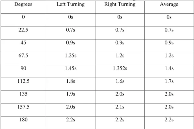
Next by utilizing the sumo-bot we were able to find out its real turn times for each 22.5 degree interval. The sumo-bot was commanded wirelessly to rotate up to 180 degrees in both the left and right directions covering all 360 degrees. I was able to gather the time needed for the sumo-bot to rotate to a specific degree consistently at a particular (fully charged) battery level. Much of the times were very close if not the same exact. Issues that probably offset some of the times is probably due to power distribution and traction with the individual wheels. The left and right times were then averaged for each of their corresponding degree threshold and interpolated by a second order polynomial to the data points of empirically acquired turn times of a 180 degree span. These correlation are represented with a Table 1. Figure 4 shows the data points of turn angle (horizontal axis) verse turn time (vertical axis) and the second order polynomial interpretation (solid plot).
25
Figure 2 : Shown above is the Cat Tran GPS latitude and longitude route coordinates
26
Table 1: Sumo-bot turn times and averages
Degrees Left Turning Right Turning Average
0 0s 0s 0s 22.5 0.7s 0.7s 0.7s 45 0.9s 0.9s 0.9s 67.5 1.25s 1.2s 1.2s 90 1.45s 1.352s 1.4s 112.5 1.8s 1.6s 1.7s 135 1.9s 2.0s 2.0s 157.5 2.0s 2.1s 2.0s 180 2.2s 2.2s 2.2s
27
CHAPTER 5: FUTURE WORK
I wish to be able to create a joint collaboration between a private corporation and WCU. Being able to achieve a new bond with a company that wish to look for new emerging
engineering or otherwise talent on the WCU campus. I wish to help lead technical sales initiatives by ways of demonstrations to Transbotics Research and Design teams, in building a new collaborative relationship that hasn’t been there before. I hope to give rise to a new and profitable business direction for Transbotics, while establishing a positive lasting impression for Western Carolina University.
Looking back at my current research I can see that though I am proud of the work that has been accomplished, there is always more that can be done. I can see more areas that can be added towards my current progress, such as the integration of object identification into future designs. Real time object identification will give these autonomous machines the ability to recognize or locate appropriate items, and doing with them on user demand. After all three areas have been completed the project could move to the integration process utilizing GPS local navigation, local orientation and object identification combine. I have also created a summer internship budget plans that Transbotics will have the option of supporting to continue their research through the summer or possibly even longer. I developed three distinct plans that all have their strengths. The budget for the three plans can be seen Figures 5, 6, and 7.
Each Internship plan has many similar styles except when it comes to both the salaries of the engineering student interns as well as the weekly working hours associated with the
internship staff. The optimal plan really gives a competitive rate to attract good engineering talent over the summer at a rate of $15 per hour while working up to 35 hours per a week. The
28
optimal plan is the most expensive but with such a competitive rate and plentiful hours much research is sure to be completed rapidly. The second plan is the economic where the engineering students are paid $12.50 per hour, while working 30 hours a week. The economic plan was developed as a moderate in between where the engineering students are still receiving a great wage but also allows Transbotics to save some money on their sponsoring side as well. The last plan is called the conservative plan, this plan is the most affordable plan developed. The
conservative plan allows Transbotics to pay engineering student interns $10 per hour, working for 25 hours a week. This plan is still a winner for $10 an hour is typically the standard rate for interns. The conservative plan allows Transbotics to maximize their savings, while still pursuing new alternatives to further their presence within the AGV market.
29
CHAPTER 6: CONCLUSION
In conclusion this project has had many benefits. The GPS module has been used completely as it was designed to do as planned for my thesis research while working for
Transbotics. I had grasped a more in-depth knowledge about different standardizations that deal with GPS mapping sequences and other data transfers. Also using orientation techniques to better create a more accurate sumo-bot moving within 360 degrees. Transbotics has seen this research and is pleased with the current outcome of the navigational mapping. I look forward to
30
31
32
33
BIBLIOGRAPHY
[1] T. Corporation, "AGC automatic guided vehicle manufacturer automated guided carts",Transbotics.com, 2016. [Online]. Available:
http://www.transbotics.com/products/automated-guided-cart. [Accessed: 09- Apr- 2016]. [2] T. Corporation, "AGV automatic guided vehicle manufacturer", Transbotics.com, 2016.
[Online]. Available: http://www.transbotics.com/products/automatic-guided-vehicles. [Accessed: 09- Apr- 2016].
[3] E. Eitel, "Basics of Rotary Encoders: Overview and New Technologies", Machinedesign.com, 2016. [Online]. Available:
http://machinedesign.com/sensors/basics-rotary-encoders-overview-and-new-technologies-0. [Accessed: 09- Apr- 2016].
[4] T. Corporation, "Guidance and Navigation for AGV and AGC automatic guided vehicle manufacturer", Transbotics.com, 2016. [Online]. Available:
http://www.transbotics.com/learning-center/guidance-navigation. [Accessed: 09- Apr- 2016].
[5] "natalia_nikolova", Antentop.org, 2016. [Online]. Available:
http://antentop.org/contributor/natalia_nikolova.htm. [Accessed: 09- Apr- 2016].
[6] "Overview of Modulated and Pulsed Diode Laser Systems", http://www.markettechinc.net/, 2016. [Online]. Available: http://www.markettechinc.net/pdf/Diode Laser Application Note.pdf. [Accessed: 09- Apr- 2016].
[7] "Gyroscopes - Everything you needed to know", Gyroscopes.org, 2016. [Online]. Available: http://www.gyroscopes.org/how.asp. [Accessed: 09- Apr- 2016].
[8] "Accelerometer Introduction to Acceleration Measurement", OMEGA, 2016. [Online]. Available: http://www.omega.com/prodinfo/accelerometers.html. [Accessed: 09- Apr- 2016].
[9] C. Hegarty and E. Chatre, "Evolution of the Global Navigation SatelliteSystem (GNSS)",Proceedings of the IEEE, vol. 96, no. 12, pp. 1902-1917, 2008.
34 APPENDIX GetPosition.m Code: i=1; %Written by Dr Tay while 1
[lat, long, time_h,time_m,time_s,AMPM]=getSerialData(9600,1); position.lat(i)=lat; position.long(i)=long; position.time_h(i)=time_h; position.time_m(i)=time_m; position.time_s(i)=time_s; position.AMPM(i,1:2)=AMPM; i=i+1;
save('myposition','position');
end
GetserialData.m Code:
function [lat, long, time_h,time_m,time_s,AMPM]=getSerialData1(baud_rate,COM_no)
% All rights are reserved.
%Written by Dr. Tay and Kyle Johnson %if isempty(s)
COM=['COM' num2str(COM_no)]; s = serial(COM,'BaudRate',baud_rate);
%set(s,'BaudRate',19200);
set(s,'DataBits',8); set(s,'Parity','none'); set(s,'StopBits',1); set(s,'flowcontrol','none'); set(s,'Timeout',1000);
%Async means that re read the port continuously.
s.ReadAsyncMode = 'continuous';
%Set the Terminator to be a Carriage Return this can be changed as requred
%but CR is a simple end char.
set(s,'Terminator','CR');
s.BytesAvailableFcnMode = 'terminator';
%On receiving data on the port send the code to the function. % s.BytesAvailableFcn = @IncomingData;
%Open the Serial Port
fopen(s); %end temp2=[0 0]; i=0; while 1 % temp=fread(fid,1,'char'); temp=fscanf(s,'%c',1); if isempty(temp) break end temp2(i+1)=temp; if temp2==['L''L'] % fread(fid,1,'char');
35 fscanf(s,'%c',1); k=1; while temp~=13 % temp=fread(fid,1,'char'); temp=fscanf(s,'%c',1); temp3(k)=temp; k=k+1; end % fread(fid,1,'char'); fscanf(s,'%c',1); x=[]; x=find(temp3=='V'); if isempty(x) char(temp3); degree_lat = (temp3(1)-48)*10+(temp3(2)-48); minutes_lat = (temp3(3)-48)*10+(temp3(4)-48)+... (temp3(6)-48)*0.1+(temp3(7)-48)*0.01+... (temp3(8)-48)*0.001+(temp3(9)-48)*0.0001; if temp3(11)=='N' lat= degree_lat+minutes_lat/60; else lat= -(degree_lat+minutes_lat/60); end degree_long = (temp3(13)-48)*100+(temp3(14)-48)*10+... (temp3(15)-48); minutes_long = (temp3(16)-48)*10+(temp3(17)-48)+... (temp3(19)-48)*0.1+(temp3(20)-48)*0.01+... (temp3(21)-48)*0.001+(temp3(22)-48)*0.0001; if temp3(24)=='E' long= degree_long+minutes_long/60; else long= -(degree_long+minutes_long/60); end time_h = ((temp3(26)-48)*10+(temp3(27)-48))-4; if time_h>=12 time_h=time_h-12; AMPM='PM'; else time_h=time_h; AMPM='AM'; end time_m = (temp3(28)-48)*10+(temp3(29)-48); time_s = (temp3(30)-48)*10+(temp3(31)-48); disp(['Latitude ',num2str(lat)])
disp(['Longitude ',num2str(long)])
disp(['Time ',num2str(time_h),':',num2str(time_m),':',num2str(time_s),' ',AMPM,' EST']) fclose(s); break end end i=i+1; i=mod(i,2); end
36 robot_navigation.c Code function robot_navigation(robot,destination) % robot_navigation(robot,destination,turnTime); %Written By Dr. Tay lat=destination.lat-robot.lat; long=destination.long-robot.long; direction=atan2d(lat,long)-robot.orientation if direction>0 disp('left') left; %pause(direction/180 * turnTime.left); % K=mod(floor(direction),45); % for k=1:K % D=P(1)*direction.^2+P(2)*direction+P(3) pause(0.5); elseif direction<0 disp('right'); right; % D=P(1)*direction.^2-P(2)*direction+P(3) pause(0.5); end stop; pause(1); disp('forward') forward; pause(0.5); stop; test_turn_times.m %Written by Dr.Tay %Directions %g=right %d=left %f=forward %v=reverse % function test_turn_time(COM_no) COM_no=2; baud_rate=9600;
COM=['COM' num2str(COM_no)]; s = serial(COM,'BaudRate',baud_rate);
%set(s,'BaudRate',19200);
set(s,'DataBits',8); set(s,'Parity','none');
37
set(s,'StopBits',1); set(s,'flowcontrol','none'); set(s,'Timeout',1000);
%Async means that re read the port continuously.
s.ReadAsyncMode = 'continuous';
%Set the Terminator to be a Carriage Return this can be changed as requred
%but CR is a simple end char.
set(s,'Terminator','CR');
s.BytesAvailableFcnMode = 'terminator';
%On receiving data on the port send the code to the function. % s.BytesAvailableFcn = @IncomingData;
%Open the Serial Port
fopen(s); fprintf(s,'g'); % right pause(.5); fprintf(s,' '); fclose(s);delete(s); clear s GPSOrientation.m Code
% Written by Dr. Tay and Wesely Dixon prompt = 'Enter Original Longitude: '; prompt2 = 'Enter Original Lattitude: '; prompt3 = 'Enter Front End Longitude: '; prompt4 = 'Enter Front End Lattitude: '; longOrg = input(prompt); latOrg = input(prompt2); longFront = input(prompt3); latFront = input(prompt4);
longDelt = longFront - longOrg; latDelt = latFront - latOrg;
if longFront>longOrg && latFront>latOrg
degree = (90-(atan(abs(longDelt)/abs(latDelt)))*(180/pi))+270; fprintf('\nYou are facing %3.3f degrees NW\n\n',degree)
elseif longFront<longOrg && latFront<latOrg
degree = (90-(atan(abs(longDelt)/abs(latDelt)))*(180/pi))+90; fprintf('\nYou are facing %3.3f degrees SE\n\n',degree)
elseif longFront>longOrg && latFront<latOrg
degree = (90-(atan(abs(longDelt)/abs(latDelt)))*(180/pi))+180; fprintf('\nYou are facing %3.3f degrees SW\n\n',degree)
38
degree = (90-(atan(abs(longDelt)/abs(latDelt)))*(180/pi)); fprintf('\nYou are facing %3.3f degrees NE\n\n',degree)
elseif longFront==longOrg && latFront>latOrg
fprintf('\nYou are facing N\n\n')
elseif longFront==longOrg && latFront<latOrg
fprintf('\nYou are facing S\n\n')
elseif longFront>longOrg && latFront==latOrg
fprintf('\nYou are facing W\n\n')
elseif longFront<longOrg && latFront==latOrg
fprintf('\nYou are facing E\n\n') else fprintf('\nerror\n\n') end robot_main.c
#Written By Dr.Tay and Chase Weddle
#include <p24hj64gp502.h> // If another supported microcontroller is used, change this header file. #include <timer.h>
#include <stdio.h> #define FCY 4000000UL
#include <libpic30.h> // This is needed for __delay_ms(). #include <math.h>
#include <stdio.h>
_FBS (BWRP_WRPROTECT_OFF & BSS_NO_FLASH); _FGS (GSS_OFF & GCP_OFF & GWRP_OFF);
_FOSCSEL (FNOSC_FRC & IESO_OFF);
_FOSC (FCKSM_CSDCMD & IOL1WAY_OFF & OSCIOFNC_OFF & POSCMD_NONE); _FWDT(FWDTEN_OFF);
_FPOR(FPWRT_PWR1 & ALTI2C_OFF); // Global variables
const unsigned char nl=10, cr=13, tab=9, percent=37,space=32; unsigned char direction=0;
// UART initialization function
//parameter BAUDRATEREG1 determines baud speed void UART1Init(int BAUDRATEREG1)
{
//Set up registers
U1BRG = BAUDRATEREG1; //set baud speed U1MODE = 0x8000; //turn on module U1STA = 0x8400; //set interrupts
39
//reset RX interrupt flag IFS0bits.U1RXIF = 0; }
//UART transmit function, parameter Ch is the character to send void UART1PutChar(char Ch)
{
//transmit ONLY if TX buffer is empty while(U1STAbits.UTXBF == 1); U1TXREG = Ch;
}
//UART receive function, returns the value received. char UART1GetChar()
{
char Temp;
//wait for buffer to fill up, wait for interrupt while(IFS0bits.U1RXIF == 0);
Temp = U1RXREG; //reset interrupt IFS0bits.U1RXIF = 0; //return my received byte return Temp; } void serial_out_motor_parameters(){ double value; char sbuf[30]; int i; UART1PutChar(direction); UART1PutChar(tab); value = (double)OC1RS / PR2; sprintf(sbuf,"OC1RS %2.2f",value*100); i=0; while(sbuf[i]!='\0') { UART1PutChar(sbuf[i]); i++; } UART1PutChar(percent); UART1PutChar(tab); value = (double)OC3RS / PR2; sprintf(sbuf,"OC3RS %2.2f",value*100); i=0; while(sbuf[i]!='\0') { UART1PutChar(sbuf[i]); i++; } UART1PutChar(percent); UART1PutChar(nl); UART1PutChar(cr); }
40
void stop(){ OC1RS=0; OC3RS=0;
RPOR5bits.RP10R=0b00000; // Map null to RP10 RPOR4bits.RP8R=0b00000; // Map null to RP8 RPOR5bits.RP11R=0b00000; // Map null to RP11 RPOR4bits.RP9R=0b00000; // Map null to RP9 PORTB&=0xF0FF; direction='x'; } void accelerate(){ if(OC1RS<PR2/2){ OC1RS=PR2/2; } else if(OC1RS<PR2){ OC1RS+=100; } if(OC3RS<PR2/2){ OC3RS=PR2/2; } else if(OC3RS<PR2){ OC3RS+=100; } } void deccelerate(){ if(OC1RS>PR2/2){ OC1RS-=100; } if(OC3RS>PR2/2){ OC2RS-=100; } } void forward(){
RPOR5bits.RP11R=0b00000; // Map null to RP11 RPOR4bits.RP9R=0b00000; // Map null to RP9 RPOR5bits.RP10R=0b10100; // Map OC3 to RP10 RPOR4bits.RP8R=0b10010; // Map OC1 to RP8 PORTB&=0xF5FF;
accelerate(); direction='f'; }
void reverse(){
RPOR5bits.RP10R=0b00000; // Map null to RP10 RPOR4bits.RP8R=0b00000; // Map null to RP8 RPOR5bits.RP11R=0b10100; // Map OC3 to RP11 RPOR4bits.RP9R=0b10010; // Map OC1 to RP9 PORTB&=0xFAFF; //accelerate(); OC1RS=2500; OC3RS=OC1RS; direction='v'; }
41
void left(){
RPOR4bits.RP9R=0b00000; // Map null to RP9 RPOR5bits.RP10R=0b00000; // Map null to RP10 RPOR4bits.RP8R=0b10010; // Map OC1 to RP8 RPOR5bits.RP11R=0b10100; // Map OC3 to RP11 PORTB&=0xF6FF; //accelerate(); OC1RS=2000; OC3RS=OC1RS; direction='l'; } void right(){
RPOR4bits.RP8R=0b00000; // Map null to RP8 RPOR5bits.RP11R=0b00000; // Map null to RP11 RPOR4bits.RP9R=0b10010; // Map OC1 to RP9 RPOR5bits.RP10R=0b10100; // Map OC3 to RP10 PORTB&=0xF9FF; //accelerate(); OC1RS=2000; OC3RS=OC1RS; direction='r'; } double rangeFinder(){
float const velocity=0.1275; // Approximately the speed of sound in inches here in Cullowhee float timer=0;
double distance=0;
TRISBbits.TRISB5=0; // Transmit sound pin set to output. PORTBbits.RB5=0; // Transmit sound pin set low. __delay_us(50);
PORTBbits.RB5=1; // Transmit sound pin set high. __delay_us(20);
PORTBbits.RB5=0; //Transmit sound pin set low. TRISBbits.TRISB6=1; // Listen pin set as input
while(!PORTBbits.RB6){ // Wait for listen pin to be set high by range finder }
while(PORTBbits.RB6){ // While listen pin is high, count 0.5 every 100 us timer+=0.5; __delay_us(100); } if(timer>90){ timer=90; } else { timer++; } distance=velocity*timer*12; __delay_ms(15);
42 return distance; } int main() { //double dist; //char buffer[30]; //int i; OSCTUN=0x0011; RCONbits.SWDTEN = 0;
TRISB = 0xF0B7; //configure PORTB
RPINR18bits.U1RXR = 2; //UART1 receive set to RB2 to tx on breakout board. RPOR1bits.RP3R = 3; //UART1 transmit set to RB3 to rx on breakout board. AD1PCFGL=0x1fff;
PORTB&=0xF0FF;
ODCBbits.ODCB7=1;
// INTCON2bits.INT0EP=1; // Interrupt occurs on - edge // IFS0bits.INT0IF=0; // sets the INT0 flag to 0
// IPC0bits.INT0IP=7; // set the INT0 priority to 7 // IEC0bits.INT0IE=0; // enable INT0
unsigned char data,data1;
ODCBbits.ODCB11=1; // 5V connected to RPll through a 1K ohm resistor. ODCBbits.ODCB10=1; // 5V connected to RPl0 through a 1K ohm resistor. ODCBbits.ODCB8=1; // 5V connected to RP8 through a 1K ohm resistor. ODCBbits.ODCB9=1; // 5V connected to RP9 through a 1K ohm resistor. // Initialize Output Compare Module
OC1CONbits.OCM = 0b000; // Disable Output Compare Module OC1RS = 0; // Write the duty cycle for the first PWM pulse // The output duty cycle is OC1RS/PR2.
OC1CONbits.OCTSEL = 0; // Select Timer 2 as output compare time base OC1CONbits.OCM = 0b110; // Select the Output Compare mode
OC3CONbits.OCM = 0b000; // Disable Output Compare Module OC3CONbits.OCTSEL=0; // Select Timer 2 as output compare time base OC3CONbits.OCM=0b110; // Select the Output Compare mode
OC3RS = 0;
RPOR7bits.RP15R=0b10011; // Map OC2 to RP15
OC2CONbits.OCM = 0b000; // Disable Output Compare Module OC2CONbits.OCTSEL=1; // Select Timer 3 as output compare time base OC2CONbits.OCM=0b110; // Select the Output Compare mode
OC2RS = 53;
// Initialize and enable Timer2
T2CONbits.TON = 0; // Disable Timer
T2CONbits.TCS = 0; // Select internal instruction cycle clock T2CONbits.TGATE = 0; // Disable Gated Timer mode T2CONbits.TCKPS = 0b00; // Select 1:1 Prescaler TMR2 = 0x0000; // Clear timer register
43
PR2 = 5000; // Load the period value T2CONbits.TON = 1; // Start Timer // Initialize and enable Timer3
T3CONbits.TON = 0; // Disable Timer
T3CONbits.TCS = 0; // Select internal instruction cycle clock T3CONbits.TGATE = 0; // Disable Gated Timer mode T3CONbits.TCKPS = 0b00; // Select 1:1 Prescaler TMR3 = 0x0000; // Clear timer register
PR3 = 106; // Load the period value T3CONbits.TON=1;
IPC1bits.T2IP = 0x01; // Set Timer 2 Interrupt Priority Level IFS0bits.T2IF = 0; // Clear Timer 2 Interrupt Flag
IEC0bits.T2IE = 0; // Disable Timer 2 interrupt stop();
UART1Init(25); //Initiate UART1 to 9600 at 8MHz __delay_ms(1000); //data=UART1GetChar(); serial_out_motor_parameters(); __delay_ms(500); while (1) { data=UART1GetChar(); data1=UART1GetChar(); UART1PutChar(data); //UART1PutChar(nl); //UART1PutChar(cr); switch (data) { case 'f': if(direction!='f'){ stop(); __delay_ms(100); } forward(); //direction='f'; break; case 'v': if(direction!='v'){ stop(); __delay_ms(100); } reverse(); //direction='v'; break; case 'g': // right if (direction!='r'){ stop(); __delay_ms(100); } right(); //direction='r'; break; case 'd': // left
44 if (direction!='l'){ stop(); __delay_ms(100); } left(); //direction='l'; break; case '-': deccelerate(); break; default: stop(); //direction=0; break; } //serial_out_motor_parameters(); } return 0; }
void __attribute__((__interrupt__, auto_psv)) _INT0Interrupt(void) { //while(!PORTBbits.RB7){ // __delay_us(200); // if(!PORTBbits.RB7){ stop(); direction='x'; serial_out_motor_parameters(); asm("RESET"); // } // } IFS0bits.INT0IF=0; }