Guide
PanelMate Power Series
otherwise, without prior written permission of Cutler-Hammer, Inc.
RESTRICTED RIGHTS LEGEND
Use, duplication, or disclosure by the Government is subject to restrictions set forth in paragraph (b)(3)(B) of the Rights in Technical Data and Computer Software clause of DAR 7-104.9(a). Contractor/Manufacturer is Cutler-Hammer, P.O. Box 6166 Westerville, OH 43086-6166.
TRADEMARKS
AcceleratI/On is a trademark of Cutler-Hammer, Inc.TouchPanel is a trademark of Cutler-Hammer, Inc. PowerBlink is a trademark of Cutler-Hammer, Inc. PowerAnimation is a trademark of Cutler-Hammer, Inc. PowerGraphics is a trademark of Cutler-Hammer, Inc. PanelMate is a registered trademark of Cutler-Hammer, Inc.
Microsoft and Windows are registered trademarks of Microsoft Corporation. Modbus is a trademark of Schneider Automation Inc.
Remote I/O, DH-485, Data Highway, and Data Highway Plus are trademarks of Allen-Bradley Company, Inc. GEnius I/O is a trademark of GE Fanuc Automation North America, Inc.
DCS-NET is a trademark of Reliance Electric Company.
Commercial names of products from other manufacturers or developers that appear in this manual are registered or unregistered trademarks of those respective manufacturers or developers, which have expressed neither approval nor disapproval of Cutler-Hammer products.
Copyright Cutler-Hammer, Inc. 1998. All rights reserved. Printed in the United States of America.
Table Of Contents i
How To Use This Manual ...2
How this manual is organized...2
Support Services ...3
Chapter 2 - Hardware Checkout Overview ...3
Unpacking...4
Checklists ...5
PanelMate 2000 Grayscale Keypad...5
PanelMate 2000 Color Keypad ...5
PanelMate 3000 Keypad ...5
PanelMate 4000 Keypad (Split Architecture) ...6
PanelMate 4000 Keypad ...6
PanelMate 5000 Keypad (Split Architecture) ...6
PanelMate 5000 Keypad ...7
PanelMate 3000 Touchscreen ...7
PanelMate 4000 Touchscreen ...7
PanelMate 5000 Touchscreen ...8
Attaching the Keyboard: Split Architecture Units ...9
Check System Health ...10
Connect AC Power ...16
Power Up The Unit ...17
Go To Offline Mode ...17
Offline Mode Menu ...18
Execute Diagnostics ...18
Set Date and Time ...19
Perform Display Tests...19
Perform Keypad Test ...20
Perform Touchscreen Test ...20
Check the Tone and Fault Relay, and Test the Battery ...20
System Status ...20
ii Table Of Contents
Calibrate Touchscreen ...24
Calibrating In Run Mode ...24
Chapter 3 - Installation in an Industrial Enclosure ...25
PanelMate 2000 Grayscale Keypad ...26
PanelMate 2000 Color Keypad...34
PanelMate 3000 Keypad...42 PanelMate 4000 Keypad...47 PanelMate 4000 Keypad...56 PanelMate 5000 Keypad...64 PanelMate 5000 Keypad...69 PanelMate 3000 Touchscreen...74 PanelMate 4000 Touchscreen...79 PanelMate 5000 Touchscreen...85 Connect AC Power ...90
Connect to a Serial Port...91
Connect to a Personal Computer ...91
Serial Port Termination...92
Connect to the Fault Relay ...93
Connect to the Audio Output ...93
Connect to the Security Keyswitch ...94
Chapter 4 - Maintenance ...97
Regular Maintenance...98
Monitor Adjustments...98
Touchscreen Cleaning Mode...100
Calibrate Touchscreen ...101
Touchscreen Replacement...102
Table Of Contents iii
Audio Output Problems ...105
Fault Relay Problems ...106
Printer Problems...106
Problems when Transferring Memory ...107
Real-Time Clock Problems...107
Communications Problems using the Generic Protocol ...107
Specific Error Messages...108
Appendix A - Detailed Specifications...109
Introduction ...110
PanelMate 2000 Grayscale Keypad ...110
PanelMate 2000 Color Keypad...113
PanelMate 3000 Grayscale Keypad ...115
PanelMate 3000 Color Dual-Scan Keypad ...118
PanelMate 3000 Color Active Matrix TFT Keypad...120
PanelMate 4000 (Split Architecture) Keypad...122
PanelMate 4000 Keypad...125
PanelMate 5000 Keypad...128
PanelMate 5000 Keypad...130
PanelMate 3000 Grayscale Touchscreen ...133
PanelMate 3000 Color Dual-Scan Touchscreen ...135
PanelMate 3000 Color Active Matrix TFT Touchscreen...137
PanelMate 4000 Touchscreen...140
iv Table Of Contents
Appendix C - Accessories and Options...159
Accessories ...160
Options ...161
Guide. This chapter describes the contents of this manual and provides information on Cutler-Hammer Support Services.
Purpose
This manual describes hardware installation of the PanelMate Power Series Operator Station.
What’s Inside
This manual is organized as follows: Preface
Chapter 1 : Introduction
Chapter 2: Hardware Checkout Overview Chapter 3: Installation In An Industrial Enclosure Chapter 4: Regular Maintenance
Chapter 5: PanelMate Unit Troubleshooting Guide Appendix A: Detailed Specifications
Appendix B: Installation Guidelines Appendix C: Accessories And Options Index
assistance. That is why we offer you so many ways to get the support you need. Whether it’s by phone, fax, modem, or mail, you can access Cutler-Hammer support information 24 hours a day, seven days a week. Our wide range of services include:
Technical Support 1-800-809-2772
If you are in the U.S. or Canada, you can take advantage of our toll-free line for technical assistance with hardware and software product selection, system design and installation, and system debugging and diagnostics. Technical support engineers are available for calls during regular business hours (8 am - 5:30 pm EST) by calling 2772. International calls can be made to either the Tech Line at 1-800-809-2772 (toll call) or the Cutler-Hammer main business line at
614-882-3282.
Emergency Technical Support 1-800-809-2772
Because machines do not run on a nine-to-five schedule, we offer emergency after-hours technical support. A technical support engineer can be paged for emergencies involving plant down situations or safety issues. Emergency support calls are automatically routed directly to our answering service after-hours (5:30 pm - 8 am EST) and weekends. For emergency technical support, call 1-800-809-2772. - Does not currently include product repairs or shipping outside normal business hours.
Technical Support Fax 614-882-0417
You can also contact our technical support engineers by faxing your support requests directly to APSC Westerville at 614-882-0417.
Information Fax-Back Service 614-899-5323
The latest Cutler-Hammer product information, specifications, technical notes and company news is available to you via fax through our direct document request service at 614-899-5323. Using a touch-tone phone, you can select any of the info faxes from our automated product literature and technical document library, punch in a fax number and receive the information immediately.
If you have modem access, you can dial in directly to our electronic bulletin board service for the latest product and company information. File sharing, product software downloads and our user message service are just a few of the things you will find online at 614-899-5209.
Website and E-mail Address http://www.cutler-hammer.eaton.com [email protected]
If you have Internet capabilities, you also have access to technical information via our website at http://www.cutler-hammer.eaton.com. The website includes technical notes, frequently asked questions, release notes, and other technical documentation. This direct technical support connection also offers you the ability to request
assistance and exchange software files electronically. Technical support messages and files can be sent to [email protected].
Software Update Service 1-800-809-2772 FAX 614-899-4141
We also offer you the opportunity to take advantage of software upgrades, advanced software notices, and special software promotions through our Software Update Service. When you register your software, you will receive one-year of free or reduced-price upgrades along with all the other benefits of membership, including 48-hour shipping of software upgrades. Contact the Software Update Service at
1-800-809-2772 or fax 614-899-4141.
Repair and Upgrade Service 614-882-3282 ext. 7601 FAX 614-882-3414
Our well-equipped Customer Service department is ready to assist you with repairs, upgrades, and spare parts services. If a situation arises where one of these services is needed, just call 614-882-3282 x7601 or fax 614-882-3414.
Product Ordering Service 614-882-3282 FAX 614-882-6532
Authorized Cutler-Hammer distributors may place product orders directly with our Order Processing department by calling 614-882-3282 x406 or faxing 614-882-6532. For information on your local distributor, call the Cutler-Hammer Tech Line.
assistance for Cutler-Hammer standard and component product lines through the Customer Support Center. Call the Customer Support Center for the following assistance:
1. Stock availability, proof of shipment, or to place an order. 2. Expedite an existing order.
3. Product assistance and product price information. 4. Product returns other than warranty returns.
For information on your local distributor or sales office, call the Cutler-Hammer Tech Line at 1-800-809-2772.
Correspondence Address Cutler-Hammer
173 Heatherdown Drive Westerville, OH 43081
1
In this chapter, you will learn:
• How to use this manual
This manual contains everything you need to know about the assembly, installation, operation, and maintenance of a PanelMate unit
PanelMate units can have up to 15 pages and 500 messages, or 100 pages and 5000 messages, depending on your unit. Appendix C gives details of available options.
The terms PanelMate Power Series and PanelMate unit will be used to describe features common to the PanelMate Power Series: 2000, 3000
,
4000, and 5000. Features unique to a particular PanelMate Power Series model will be noted as such.This manual is written for system engineers, plant engineers or maintenance personnel and Cutler-Hammer personnel; any persons who may be involved in configuring screens, or installing and maintaining a PanelMate unit. This manual is not written for plant personnel who will be using the PanelMate unit to control factory operations. The task of informing plant operators how to use the PanelMate unit in specific situations is left to those who configured the screens.
the operation of our products. We are dedicated to providing fast, friendly, and accurate assistance. That is why we offer you so many ways to get the
support you need. Whether it’s by phone, fax, modem, or mail, you can access Cutler-Hammer support information 24 hours a day, seven days a week. Our wide range of services include:
Technical Support 1-800-809-2772
If you are in the U.S. or Canada, you can take advantage of our toll-free line for technical assistance with hardware and software product selection, system design and installation, and system debugging and diagnostics. Technical support engineers are available for calls during regular business hours (8 am - 5:30 pm EST) by calling 1-800-809-2772. International calls can be made to either the Tech Line at 1-800-809-2772 (toll call) or the Cutler-Hammer main business line at
614-882-3282.
Emergency Technical Support 1-800-809-2772
Because machines do not run on a nine-to-five schedule, we offer emergency after-hours technical support. A technical support engineer can be paged for emergencies involving plant down situations or safety issues. Emergency support calls are automatically routed directly to our answering service after-hours (5:30 pm - 8 am EST) and weekends. For emergency technical support, call 1-800-809-2772. This does not currently include product repairs or shipping outside normal business hours.
Technical Support Fax 614-882-0417
You can also contact our technical support engineers by faxing your support requests directly to APSC Westerville at 614-882-0417.
and company news is available to you via fax through our direct document request service at 614-899-5323. Using a touch-tone phone, you can select any of the info faxes from our automated product literature and technical document library, punch in a fax number and receive the information immediately.
Bulletin Board Service 614-899-5209
Parameters: 8 data bits, 1 stop bit, parity none, 9600-28.8K baud. If you have modem access, you can dial in directly to our electronic bulletin board service for the latest product and company information. File sharing, product software downloads and our user message service are just a few of the things you will find online at 614-899-5209.
Website and E-mail Address http://www.cutler-hammer.eaton.com [email protected]
If you have Internet capabilities, you also have access to technical information via our website at http://www.cutler-hammer.eaton.com. The website includes technical notes, frequently asked questions, release notes, and other
technical documentation. This direct technical support connection also offers you the ability to request assistance and exchange software files
electronically. Technical support messages and files can be sent to [email protected].
Software Update Service 1-800-809-2772
FAX 614-899-4141
We also offer you the opportunity to take advantage of software upgrades, advanced software notices, and special software promotions through our Software Update Service. When you register your software, you will receive one-year of free or reduced-price upgrades along with all the other benefits of membership, including 48-hour shipping of software upgrades. Contact the Software Update Service at 1-800-809-2772 or fax 614-899-4141.
repairs, upgrades, and spare parts services. If a situation arises where one of these services is needed, just call 614-882-3282 x7601 or fax 614-882-3414.
Product Ordering Service 614-882-3282
FAX 614-882-6532
Authorized Cutler-Hammer distributors may place product orders directly with our Order Processing department by calling 614-882-3282 x406 or faxing 614-882-6532. For information on your local distributor, call the Cutler-Hammer Tech Line.
Customer Support Center 1-800-356-1243
Authorized Cutler-Hammer distributors and Cutler-Hammer sales offices can get assistance for Cutler-Hammer standard and component product lines through the Customer Support Center. Call the Customer Support Center for the following assistance:
1. Stock availability, proof of shipment, or to place an order. 2. Expedite an existing order.
3. Product assistance and product price information. 4. Product returns other than warranty returns.
For information on your local distributor or sales office, call the Cutler-Hammer Tech Line at 1-800-809-2772.
Correspondence Address Cutler-Hammer
173 Heatherdown Drive Westerville, OH 43081
2
In this chapter, you will learn:
• How to set-up the PanelMate unit for checkout
• How to attach the Audio Feedback Kit
• How to attach the optional Security Keyswitch
• How to check system health
for damage in shipment. Check the packing cartons for all items shown on the packing list. Keep the cartons and packing materials for future shipment. Report any damage to the carrier who delivered the equipment and
immediately call the company from which you purchased the equipment. This may be your local distributor or Cutler-Hammer. If you purchased the
equipment from Cutler-Hammer, call the order Processing Department at (614) 882-3282.
Note The Interstate Commerce Commission has a time limit on reporting concealed damage.
On the following pages are checklists for these PanelMate unit models.
• PanelMate 2000 Grayscale Keypad Unit
• PanelMate 2000 Color Keypad Unit
• PanelMate 3000 Keypad Unit
• PanelMate 4000 (Split Architecture) Keypad Unit
• PanelMate 4000 Keypad Unit
• PanelMate 5000 (Split Architecture) Keypad Unit
• PanelMate 5000 Keypad Unit
• PanelMate 3000 Touchscreen Unit
• PanelMate 4000 Touchscreen Unit
• PanelMate 5000 Touchscreen Unit
PanelMate 2000 Grayscale Keypad Unit
• 1 PanelMate Series 2000 Grayscale Keypad Unit
• 1 Hardware Manual
• 1 Shipping kit (plastic bag) containing:
− 1 Packet of mounting nuts and washers - 16 #8 nuts, 16 #8 washers
− 2 two-terminal connectors
− 1 three-terminal connector
− 1 Cutout/torque drawing
PanelMate 2000 Color Keypad Unit
• 1 PanelMate 2000 Color Keypad Unit
• 1 Hardware Manual
• 1 Shipping kit (plastic bag) containing:
− 1 Packet of mounting nuts and washers - 16 #8 nuts, 16 #8 washers
− 2 two-terminal connectors
− 1 three-terminal connector
− 1 Cutout/torque drawing
PanelMate 3000 Keypad Unit
• 1 PanelMate 3000 Keypad Unit
• 1 Hardware Manual
• 1 Shipping kit (plastic bag) containing:
− 1 Packet of mounting nuts and washers - 16 #8 nuts, 16 #8 washers
− 2 two-terminal connectors
− 1 three-terminal connector
• 1 TouchPanel
• 1 Hardware Manual
• 1 Shipping kit (plastic bag) containing:
− 1 Packet of mounting nuts and washers - 16 #10 nuts, 16 #10 washers, 12 #8 nuts, 12 #8 washers
− 2 two-terminal connectors
− 1 three-terminal connector
− 1 Cutout/torque drawing
PanelMate 4000 Keypad Unit
• 1 PanelMate 4000 Keypad Unit
• 1 Hardware Manual
• 1 Shipping kit (plastic bag) containing:
− 1 Packet of mounting nuts and washers - 18 #10 nuts, 18 #10 washers
− 2 two-terminal connectors
− 1 three-terminal connector
− 1 Cutout/torque drawing
PanelMate 5000 (Split Architecture) Keypad Unit
• 1 PanelMate 5000 Keypad Unit with cable
• 1 TouchPanel
• 1 Hardware Manual
• 1 Shipping kit (plastic bag) containing:
− 1 Packet of mounting nuts and washers - 16 #10 nuts, 16 #10 washers, 12 #8 nuts, 12 #8 washers
− 2 two-terminal connectors
− 1 three-terminal connector
• 1 Hardware Manual
• 1 Shipping kit (plastic bag) containing:
• 1 Packet of mounting nuts and washers - 18 #10 nuts, 18 #10 washers
− 2 two-terminal connectors
− 1 three-terminal connector
− 1 Cutout/torque drawing
PanelMate 3000 Touchscreen Unit
• 1 PanelMate 3000 Touchscreen Unit
• 1 Hardware Manual
• 1 Shipping kit (plastic bag) containing:
− 1 Packet of mounting nuts and washers - 16 #8 nuts, 16 #8 washers
− 2 two-terminal connectors
− 1 three-terminal connector
− 1 Cutout/torque drawing
PanelMate 4000 Touchscreen Unit
• 1 PanelMate 4000 Touchscreen Unit
• 1 Hardware Manual
• 1 Shipping kit (plastic bag) containing:
− 1 Packet of mounting nuts and washers - 18 #10 nuts, 18 #10 washers
− 2 two-terminal connectors
− 1 three-terminal connector
• 1 Hardware Manual
• 1 Shipping kit (plastic bag) containing:
− 1 Packet of mounting nuts and washers 18 #10 nuts, 18 #10 washers
− 2 two-terminal connectors
− 1 three-terminal connector
− 1 Cutout/torque drawing
If you ordered a Mounting Collar Kit as an accessory for a PanelMate 2000 Keypad uni, it will be packaged separately:
• 1 Mounting Collar
• Packeted mounting hardware - 16 #8 nuts, 16 #8 washers
• 1 Cutout/torque drawing
• 1 Gasket
If you ordered a Mounting Collar Kit as an accessory for a PanelMate 4000 (Split Architecture) Keypad Unit, it will be packaged separately:
• 2 Mounting Collars
• Packeted mounting hardware - 14 #10 nuts, 14 #10 washers - 12 #8 nuts, 12 #8 washers
• 1 Cutout/torque drawing
• 2 Gaskets
If you ordered a Mounting Collar Kit as an accessory for a PanelMate 4000 Keypad Unitt, it will be packaged separately:
• 1 Mounting Collar
• Packeted mounting hardware - 22 #8 nuts, 22 #8 washers
• 1 Cutout/torque drawing
• 1 Transfer Utility with manual
• 1 Packet of mounting nuts and washers containing - 18 #8 nuts, 18 #8 washers, 18 #10 nuts, 18 #10 washers
• 1 Packet of connectors - 2 two-terminal connectors - 1 three-terminal connector
• 1 Packet with a three-terminal connector
• 8 Cutout/torque drawings
• 1 22.5 mm security keyswitch (with 2 keys)
If you ordered an Audio Feedback Kit as an accessory, it will be packaged separately:
• 1 Speaker with 24-foot connecting cable attached
If you ordered a PLC cable as an accessory, it will be packaged separately:
• 1 PLC cable
If you ordered a Serial Transfer cable as an accessory, it will be packaged separately:
Note This procedure is for Split Architecture units only.
To attach the keyboard to the Keypad Unit and ensure proper grounding, follow this procedure.
1. Plug the keyboard cable into the keypad.
2. Ensure that the keyboard metal clamp is over the braided shield area of the cable.
3. Place the star washer between the keypad standoff and the keyboard cable metal clamp.
4. Place the flat washer next to the keyboard cable metal clamp. 5. Tighten the screw to secure the keyboard cable.
Figure 2-1 PanelMate 4000 & 5000 Keypad Unit Keyboard Star Washer
Keypad
You may wish to test your unit before you install it in your industrial enclosure. This section outlines the steps required to set-up the PanelMate unit on a work surface for check-out before installation. You will be performing the following procedure:
1. Connect to AC Power.
2. Attach the optional Audio Feedback Kit. 3. Attach the optional Security Keyswitch. 4. Power Up the Unit.
5. Execute the System Diagnostics:
• Set Date and Time
• Perform Display Tests
• Perform Keypad Test
• Check Audio Output, Fault Relay, and Test Battery
Figure 2-3 PanelMate 2000 Color Keypad Unit Rear View
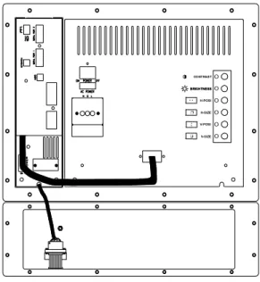
Figure 2-5 PanelMate 4000Keypad Unit Rear View
❐ ❐ ❐ ❐ Figure 2-6 PanelMate 4000 Keypad Unit Rear View
H-POSI H-SIZE BRIGHTNESS V-POSI V-SIZE CO NTRAST BRIGHTNESS O O O O O O O O ↔ ❐ ↕ ❏
Figure 2-7 PanelMate 5000 Keypad Unit Side View
Figure 2-9 PanelMate 3000 Touchscreen Unit Rear View
Figure 2-10 PanelMate 4000 Touchscreen Unit Rear View H-POSI H-SIZE BRIGHTNESS V-POSI V-SIZE CO NTRAST BRIGHTNESS O O O O O O O O ↔ ❐ ↕ ❏
Figure 2-11 PanelMate 5000 Touchscreen Unit Side View
Connect AC Power
The AC power terminals and switch are on the back of the PanelMate 2000 and 4000, and on the side of the PanelMate 3000 and PanelMate 5000. Ensure the rocker switch is OFF. Remove the protective cover. Connect your AC power with user-supplied wiring.
Note For PanelMate 2000 Color and PanelMate 4000 units, the monitor and Electronics Module require individual power connection.
The PanelMate unit is auto-sensing and automatically adjusts to operate at either 120V AC or 230V AC. Replace the protective cover over the AC wiring. Note Power Conditioning may be required when the PanelMate unit is installed in
areas where the power quality is poor.
N = Neutral - White Wire (typical) G = Ground - Green/Yellow Wire (typical)
L = Line (Hot) - Black Wire (typical) Recommended minimum wire size is
The Audio Feedback Kit is an optional accessory to the PanelMate unit. To attach the speaker to the unit, remove it from the shipping box and
connect the cable to the two-terminal connector which plugs into the terminals labeled "AUDIO". The connector is shipped in a small plastic bag with the unit.
Attach Security Keyswitch
The Security Keyswitch, an optional accessory to the PanelMate unit, is included in the Hardware Support Kit.
To attach the Security Keyswitch to the unit, unpack it and connect it with user-supplied wiring to the two-terminal connector which plugs into the terminals labeled "KEYSWITCH". Note that this is a contact closure and voltage should not be applied. The connector is shipped in a small plastic bag with the unit.
Power Up the Unit
To power up the unit, follow the steps below:
1. Switch the power on. For PanelMate 2000 Color and PanelMate 4000, power up both the monitor and the Electronics Module.
Note This sequence occurs at initial power-up, or when the unit is recovering from a power interruption.
2. The PanelMate unit performs internal diagnostic checks, and the screen displays a listing of the diagnostic checks as they are executed. With PanelMate 2000 or PanelMate 4000 units, you may also hear a monitor “crackle”. This is normal. If there is a failure, see the troubleshooting guide in Chapter 5.
3. The PanelMate unit returns to the state it was in when powered off.
• If the PanelMate unit was in the Offline Mode, it will return to the Offline Mode and display the Offline Mode menu.
• If the PanelMate unit was in the Run Mode, it will return to the Run Mode and go to the Startup Page defined by the configuration loaded into the unit. The unit must be in the Offline Mode to run the
1. Select the Get Page control button from the default control buttons. 2. Select the More control button.
3. Select the Enter Offline Mode template.
4. Press the Execute control button to display the Offline Mode menu. After the PanelMate unit completes the diagnostics, proceed to the next section.
Offline Mode Menu
The offline Mode menu displays six selections which are described below. Note: Keypad units do not display the Calibrate Touchscreen selection.
Figure 2-12 Offline Mode Menu
Note After the diagnostics are complete, you can force a keypad unit into Offline Mode by pressing the lower two control buttons simultaneously. To force a touchscreen unit into the Offline Mode, press the lower right control button.
Select the template labeled "Execute Diagnostics" or use the TouchPanel mounted below the CRT on keypad units. Then press the control button labeled "Execute" to display a new page of choices.
Perform these tests by selecting the appropriate template then pressing the Execute control button:
• Set Date and Time
• Display
• Keypad
• Touchscreen
• Tone, Relay, and Battery Test
• System Status
Setting Date and Time
1. Select Set Date and Time and press the control button labeled "Execute". A new page will be displayed.
2. Select Set Date and press the control button labeled "Execute". The right hand control buttons will change and numeric entry will be enabled. Use the numeric keypads to enter the month, day of the month and the year using the format MM-DD-YY. Be sure to use the minus key between the numeric values. By pressing the control button labeled "Enter", the new date will be entered. If the date is already correct, press the <Cancel> key to exit.
3. Select Set Time and press the control button labeled "Execute". Use the numeric keys to enter the time as HH-MM-SS with the hours in the 24-hour format. For example, enter 2:45:11 PM as 14-45-11. Be sure to use the minus key between numeric values. Pressing the control button labeled "Enter" enters the new time.
If the time is already correct, press the <Cancel> key to exit.
4. Press the <Cancel> key then the bottom control button labeled "Exit" to proceed.
displays four display tests you can run. For PanelMate Grayscale units, the tests are:
• Intensity Check
• Solid No Intensity Screen
• Solid High Intensity Screen
• Dot Pattern.
For PanelMate units, the tests are:
• Color Check
• Solid Black Screen
• Solid White Screen
• Dot Pattern
Select a test and press the Execute control button. To exit a test, press <Cancel>.
Perform Keypad Test
Note This test only appears on keypad units.
Use this test to verify keyboard operation. Select Keypad Test and press the control button labeled "Execute". As a key is pressed, it is identified on the page display. Test the <Cancel> key last because it exits the test mode.
Perform Touchscreen Test
Note This test only appears on touchscreen units.
Use this test to verify touchscreen operation. Select Touchscreen Test and press the control button labeled "Execute". As the touchscreen is pressed, it is identified on the page display. Test the <Cancel> key last because it exits the test mode.
six new test selections. If you have the optional Audio Feedback Kit, follow the onscreen instructions to test the Low, Medium, and High Audio Tones. You can also call screens to test the Fault Relay and Real-Time Clock Battery.
System Status
Select System Status and press the control button labeled "Execute". The new screen displays the Power Up Diagnostic Results.
Test Completion
This completes the internal System Health Checks. Before removing your wiring, turn the power switch OFF, then disconnect the AC power source.
Enter the Serial Transfer Mode
To download, upload, or read system information over a serial port, the online unit must be in the Serial Transfer Mode. The PanelMate unit remains in the ready state until the Configuration Software initiates the transfer.
Configuration files, drivers, executive firmware, and options can be
downloaded to the PanelMate unit. The PanelMate unit configuration file can be uploaded to a personal computer.
Figure 2-13 Serial Transfer Screen
Note that you can refer to the Display System Configuration Information screen before or after a transfer to verify configuration names, executive firmware versions, options, or drivers currently loaded in the system.
default state of the electronics module when the front panel is removed and power is applied.
Use the configuration software to change the default communication rate (9600 baud) in the PanelMate unit. The PanelMate unit uses port 1 for transferring information.
Enter the Network Transfer Mode
Note The Executive Firmware and the network driver must be downloaded using the Serial Transfer Mode before you can transfer over a network.
To download, upload, remotely place the PanelMate unit into Run Mode, or read system information over a remote network, the online unit must have the Remote Transfer option installed and be in the Network Transfer Mode. The PanelMate unit will remain in the ready state until the Configuration Software has initiated the transfer. Configuration files, drivers, executive firmware, and options can be downloaded to the PanelMate unit. The configuration file loaded in the PanelMate unit can be uploaded to a personal computer. The PanelMate unit can also be remotely placed into Run Mode. For more information on remotely placing the PanelMate unit in Run Mode, refer to the Place VCP Unit in Run Mode topic in the Configuration Software Online Help.
Figure 2-14 Network Transfer Screen
You may refer to the Display System Configuration Information screen before or after a transfer to verify configuration names, executive firmware versions, options, or drivers currently loaded in the system.
Figure 2-15 System Configuration Display
Enter Run Mode
Use this mode to display the configuration in the PanelMate unit
communicating with the PLC of your choice. If the Remote Transfer option is installed, you can remotely place the PanelMate unit into Run Mode from a personal computer.
Note If the value in the Remote Mode Change field in the System Parameters table is configured as IMMEDIATE, DEFAULT, or ACCEPT, you can also remotely place the PanelMate unit into the Network Transfer Mode from your personal computer.
For more information on remotely placing the PanelMate unit into the Network Transfer Mode, refer to the Place VCP Unit in Transfer Mode topic in the Configuration Software Online Help.
Exit Run Mode
To exit the Run Mode:
1. Select "More" from the default control buttons 2. Select "Setup Page"
can also calibrate in Run Mode. See Calibrate Touchscreen in Chapter 4. This template only appears on PanelMate touchscreen units.
PanelMate touchscreen units have a calibration routine that must be performed to determine the boundaries of the video on your touchscreen. When you select the Calibrate Touchscreen template and press the Execute control button, this screen appears.
Figure 2-16 Calibration Screen
To calibrate, press each of the boxes around the outside of the page (Fig. 2-16) You may press the boxes in any order but all boxes must be pressed to complete the calibration.
Each box turns green (or different shade of gray) when pressed. After the first pass, the boxes turn red (the original shade) to indicate that the screen is ready for the second pass. After calibrating, you return to the Setup Page. Calibration settings are retained when power is removed from the PanelMate unit.
Calibrating In Run Mode
See Calibrate Touchscreen in Chapter 4 for more information.
Press these boxes.
Installation in an Industrial Enclosure
3
In this chapter, you will learn:
• How to install the PanelMate Unit in an industrial enclosure
• How to install the two-inch Mounting Collar
• How to connect AC Power
• How to connect a Printer to the PanelMate Unit
• How to connect to the Fault Relay
• How to connect to the Audio Output
PanelMate 2000 Grayscale Keypad Unit
The PanelMate 2000 Grayscale Keypad Unit is designed to be used on the factory floor, mounted in an industrial enclosure. This section contains the information about installing the PanelMate 2000 Grayscale Keypad Unit in an enclosure and the installation of the various options that may be purchased. If you will be using any of the accessories, please refer to the sections of this chapter that provide specific information about each of the accessories before proceeding with installation. The instructions in this section are based on the assumption that you have already verified unit operation by performing the system health tests defined in Chapter 2.
Enclosure Sizing
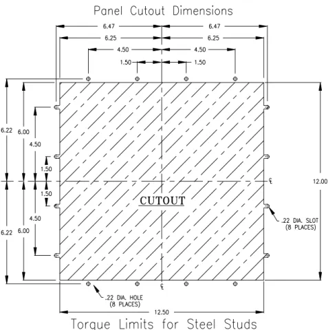
Review the PanelMate 2000 Grayscale Keypad Unit Outline and the PanelMate 2000 Grayscale Keypad Unit Panel Cutout and Torque drawings shown on the following pages. Use this information to determine the enclosure size for your application. There are a number of factors to consider when selecting an enclosure in which to house the PanelMate Unit. Although designed to withstand harsh environmental conditions, you must not expose the unit to conditions which are beyond the detailed specifications found in Appendix A. Appendix B contains guidelines concerning enclosure sizing and temperature specifications taken from enclosure manufacturers. To ensure proper convection cooling, we recommend a minimum 6-inch clearance above and 6-inch clearance below the unit when installed in an industrial enclosure.
Note All units are in inches.
Figure 3-2 PanelMate 2000 Grayscale Keypad Unit Cutout and Torque Limits
Install in an Enclosure
Make cutouts in the enclosure as show in figure 3-2. Disassemble the PanelMate Unit using the following procedure:
1. Go to the back of the unit. Remove AC power and disconnect any other cables. 2. Unplug the Monitor Module video/power cable from the Electronics Module.
This cable disconnects power and the video signal to the monitor.
3. Remove the Monitor Module. Do this by turning the quarter-turn fasteners counter-clockwise. The Monitor Module is now disconnected and will slide out. Store in a safe location.
4. Remove the Electronics Module. Do this by turning the quarter-turn fasteners counter-clockwise. Support the weight of the assembly by holding the knurled fasteners, then gently pull the assembly toward you to dis-engage the front panel keypad connector. Then pivot the assembly down to clear the mounting flange on the front panel. Store in a safe location.
5. From the front, insert the Front Panel in the cutout and fasten it with the sixteen #8 washers and nuts that are supplied with the unit.
Caution Care must be exercised when tightening the nuts. The fasteners must be tightened enough to obtain a proper seal, yet not be tightened enough to strip the threads from the welded steel studs. Do not exceed 6 inch-pounds.
6. Re-attach the Electronics Module. Do this by engaging the front slots of the Electronics Module on the mounting flange on the Front Panel. Bring the unit up to a horizontal position and slide the quarter-turn fasteners into their mounting holes on the front panel tray. Complete the assembly by turning the quarter-turn fasteners clockwise to lock in place.
7. Re-attach the Monitor Module. Slide the Monitor Module into the front panel tray and ensure the top lip overlaps the front panel lip. Turn the quarter-turn fastener clockwise to lock. Finally re-connect the video/power cable from the Monitor Module to the Electronics Module.
8. You may now re-connect AC power and cables to the Monitor and Electronics Modules.
Install the Mounting Collar
The Mounting Collar Kit is an optional accessory to the PanelMate 2000 Grayscale Keypad Unit and allows mounting a unit into a 10-inch deep enclosure. Two versions are available: standard painted finish or stainless steel. The kit consists of a collar, mounting hardware, gasket, and a cutout/torque drawing.
To install the kit, first make the panel cutout for the mounting collar as shown in figure 3-6. Check to see if the mounting collar will fit, then remove. Attach the PanelMate Unit to the mounting collar with the 16 nuts and washers provided with the PanelMate 2000 Grayscale Keypad Unit Mounting Collar Kit.
Caution Care should be exercised when tightening the nuts. The fasteners must be tightened enough to obtain a proper seal, but not tightened to the point where the threads are stripped or the gasket is rendered useless. Do not exceed 8 inch-pounds.
Attach the gasket to the mounting collar. This is most easily done by placing the unit, with the collar attached, face down on a work surface. Take care to prevent scratching the front panel of the unit. Align the outside edge of the gasket even with the outside edge of the collar with the page edge facing the collar. Attach the gasket by stripping off a small section of the paper protecting the adhesive on the gasket. Carefully attach the gasket to the collar, uncovering the adhesive a few inches at a time.
Insert the assembled collar in the panel and fasten the collar to the panel with 16 nuts and washers. Mount the PanelMate Unit's front panel to the collar and then mount collar to the enclosure. Finally, attach the Monitor Module and Electronics Module.
Figure 3-4 PanelMate 2000 Grayscale Keypad Unit (Model 2600) Mounting Collar Assembly
Figure 3-5 PanelMate 2000 Grayscale Keypad Unit (Model 2600) With Collar Outline
Panel Mount Collar
PanelMate 2000 Color Keypad Unit (Model 2700)
The PanelMate 2000 Color Keypad Unit is designed to be used on the factory floor, mounted in an industrial enclosure. This section contains the information about installing the PanelMate 2000 Color Keypad Unit in an enclosure and the installation of the various options that may be purchased. If you will be using any of the
accessories, please refer to the sections of this chapter that provide specific information about each of the accessories before proceeding with installation. The instructions in this section are based on the assumption that you have already verified unit operation by performing the system health tests defined in Chapter 2.
Enclosure Sizing
Review the PanelMate 2000 Color Keypad Unit Outline and the PanelMate 2000 Color Keypad Unit Panel Cutout and Torque drawings shown on the following pages. Use this information to determine the enclosure size for your application. There are a number of factors to consider when selecting an enclosure in which to house the PanelMate Unit. Although designed to withstand harsh environmental conditions, you must not expose the unit to conditions which are beyond the detailed specifications found in Appendix A. Appendix B contains guidelines concerning enclosure sizing and temperature specifications taken from enclosure manufacturers.
To ensure proper convection cooling, we recommend a minimum 6-inch clearance above and 6-inch clearance below the unit when installed in an industrial enclosure.
10.26 0.62 13.10
11.50 11.89 0.68
11.80
Note All units are in inches.
Figure 3-2 PanelMate 2000 Color Keypad Unit (Model 2700) Cutout and Torque Limits
Figure 3-3 PanelMate Power Series 2000 Color Keypad Unit (Model 2700) Rear View
Power Series unit using the following procedure:
1. Go to the back of the unit. Remove AC power from both the Electronics Module and the monitor housing.
2. Unplug the Monitor Module video cable from the Electronics Module. This cable disconnects the video signal to the monitor.
3. Remove the Monitor Module. Do this by turning the quarter-turn fasteners counter-clockwise. The Monitor Module is now disconnected and will slide out. Store in a safe location.
4. Remove the Electronics Module. Do this by turning the quarter-turn fasteners counter-clockwise. Support the weight of the assembly by holding the knurled fasteners, then gently pull the assembly away from the front panel to disengage the front panel keypad connector. Then pivot the assembly down to clear the mounting flange on the front panel. Store in a safe location.
5. From the front, insert the Front Panel in the cutout and fasten it with the sixteen #8 washers and nuts that are supplied with the unit.
Caution
6. Re-attach the Electronics Module. Do this by engaging the front slots of the Electronics Module on the mounting flange on the Front Panel. Bring the unit up to a horizontal position and slide the quarter-turn fasteners into their mounting holes on the front panel tray. Complete the assembly by turning the quarter-turn fasteners clockwise to lock in place.
7. Re-attach the Monitor Module. Slide the Monitor Module into the front panel tray and ensure the top lip overlaps the front panel lip. Turn the quarter-turn fastener clockwise to lock. Finally re-connect the video cable to both the Electronics Module and the monitor housing.
8. You may now re-connect AC power and cables to the Monitor and Electronics Modules.
Care must be exercised when tightening the nuts. The fasteners must be tightened enough to obtain a proper seal, yet not be tightened enough to strip the threads from the welded steel studs. Do not exceed 6 inch-pounds.
Two versions are available: standard painted finish or stainless steel. The kit consists of a collar, mounting hardware, gasket, and a cutout/torque drawing.
To install the kit, first make the panel cutouts for the mounting collar as shown in figure 3-12. Check to see if the mounting collar will fit, then remove. Attach the PanelMate Power Series unit to the mounting collar with the 16 nuts and washers provided with the PanelMate Power Series 2000 Color Mounting Collar Kit.
Caution
Attach the gasket to the mounting collar. Place the unit, with the collar attached, face down on a work surface. Take care to prevent scratching the front panel of the unit. Align the outside edge of the gasket even with the outside edge of the collar with the page edge facing the collar. Attach the gasket by stripping off a small section of the paper protecting the adhesive on the gasket. Carefully attach the gasket to the collar, uncovering the adhesive a few inches at a time.
Insert the assembled collar in the panel and fasten it to the panel with 16 nuts and washers. Mount the PanelMate Power Series unit's front panel to the collar and then mount collar to the enclosure. Finally, attach the Monitor Module and Electronics Module.
Figure 3-4 PanelMate Power Series 2000 Color Keypad Unit (Model 2700) Mounting Collar Assembly
Use care when tightening the nuts. They must be tightened enough to obtain a proper seal, but not tightened to the point where the threads are stripped or the gasket is rendered useless. Do not exceed 8 inch-pounds.
11.60 14.10 13.20 11.80 0.45 12.50 0.17 0.45 9.86 2.00 11.89 10.26 1.12
Figure 3-5 PanelMate Power Series 2000 Color Keypad Unit (Model 2700) with Collar Outline
Note All units are in inches.
Figure 3-6 PanelMate Power Series 2000 Color Keypad Unit (Model 2700) Panel Mount Collar
(Models 3600, 3700, and 3900)
The PanelMate Power Series 3000 Keypad unit is designed to be used on the factory floor, mounted in an industrial enclosure. This section contains the information about installing the PanelMate Power Series 3000 Keypad unit in an enclosure and the installation of the various options that may be purchased. If you will be using any of the accessories, please refer to the sections of this chapter that provide specific information about each of the accessories before proceeding with installation. The instructions in this section are based on the assumption that you have already verified unit operation by performing the system health tests defined in Chapter 2.
Enclosure Sizing
Review the PanelMate Power Series 3000 Keypad unit Outline and the PanelMate Power Series 3000 Keypad unit Panel Cutout and Torque drawings shown on the following pages. Use this information to determine the enclosure size for your application. There are a number of factors to consider when selecting an enclosure in which to house the PanelMate Power Series 3000 Keypad unit. Although designed to withstand harsh environmental conditions, you must not expose the unit to conditions which are beyond the detailed specifications found in Appendix A. Appendix B contains guidelines concerning enclosure sizing and temperature specifications taken from enclosure manufacturers.
To ensure proper convection cooling, we recommend a minimum 6-inch clearance above and 6-inch clearance below the unit when installed in an industrial enclosure.
Figure 3-7 PanelMate Power Series 3000 Keypad Unit (Models 3600, 3700, and 3900) Outline
Note All units are in inches.
Figure 3-8 PanelMate Power Series 3000 Keypad Unit
Figure 3-9 PanelMate Power Series 3000 Keypad Unit (Models 3600, 3700, and 3900) Side View
PanelMate Power Series 3000 Keypad unit using the following procedure:
1. Go to the side of the unit. Remove AC power and disconnect any other cables. 2. Unplug the keypad cable from the Electronics Module. Make sure you do not
pull on the keypad cable.
3. Unfasten the ferrite block from the unit. Make sure the free weight of the ferrite does not damage the keypad cable.
4. Remove the Electronics Display Assembly. Do this by turning the captive fasteners counter-clockwise. Support the weight of the assembly by holding the bottom of the unit, then gently tilt the top of the assembly and lift upward. Store in a safe location.
5. From the front, insert the Front Panel in the cutout and fasten it with the sixteen #8 washers and nuts that are supplied with the unit.
Caution
6. Re-attach the Electronics Display Assembly. Do this by engaging the front slots of the Electronics Display Assembly on the mounting flanges on the Front Panel. Raise the unit up to a horizontal position and slide the captive fasteners into their mounting holes on the front panel tray. Complete the assembly by turning the captive fasteners clockwise to lock in place.
7. Plug the connector into the Electronics Module. Make sure you do not press on the keypad cable.
8. You may now re-connect AC power and cables. Care must be exercised
when tightening the nuts. The fasteners must be tightened enough to obtain a proper seal, yet not be tightened enough to strip the threads from the welded steel studs. Do not exceed 7 inch-pounds.
The PanelMate Power Series 4000 (Split Architecture) Keypad unit is designed to be used on the factory floor, mounted in an industrial enclosure. This section contains the information about installing the PanelMate Power Series 4000
(Split-Architecture) Keypad unit in an enclosure and the installation of the various options that may be purchased. If you will be using any of the accessories, please refer to the sections of this chapter that provide specific information about each of the accessories before proceeding with installation.
The instructions in this section are based on the assumption that you have already verified unit operation by performing the system health tests defined in Chapter 2.
Enclosure Sizing
Review the PanelMate Power Series 4000 (Split Architecture) Keypad unit Outline and the PanelMate Power Series 4000 (Split Architecture) Keypad unit Panel Cutout and Torque drawings shown on the following pages. Use this information to
determine the enclosure size for your application. If the PanelMate Power Series 4000 (Split Architecture) Keypad unit will be used in a PanelMate Series I, II, or III enclosure, the cutout will have to be modified as shown in figure 3-18. There are a number of factors to consider when selecting an enclosure in which to house the PanelMate Power Series 4000 unit. Although designed to withstand harsh environmental conditions, you must not expose the unit to conditions which are beyond the detailed specifications found in Appendix A. Appendix B contains guidelines concerning enclosure sizing and temperature specifications taken from enclosure manufacturers.
To ensure proper convection cooling, we recommend a minimum 6-inch clearance above and 6-inch clearance below the unit when installed in an industrial enclosure.
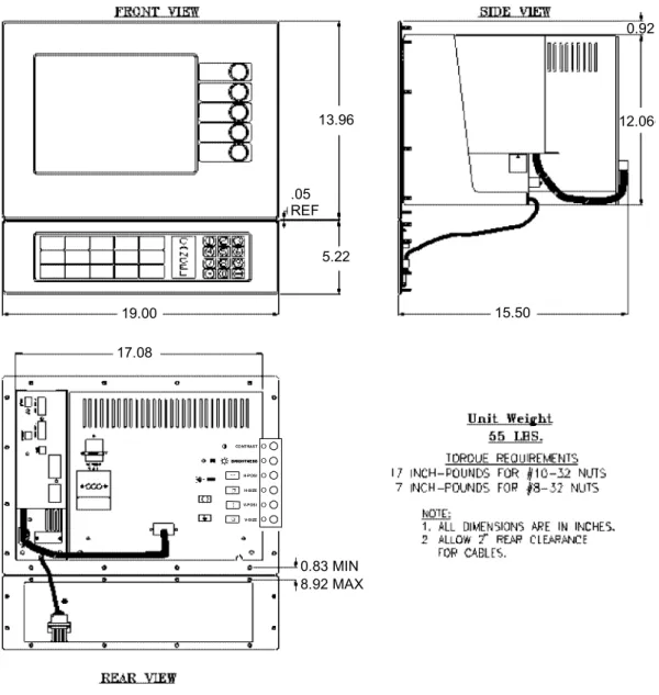
13.96 12.06 17.08 19.00 .05 REF 5.22 15.50 0.83 MIN 8.92 MAX
Figure 3-10 PanelMate Power Series 4000 Keypad Unit (Model 4200-Split Architecture) Outline
H-POSI H-SIZE BRIGHTNESS V-POSI V-SIZE CO NTRAST BRIGHTNESS O O O O O O O O ↔ ❐ ↕ ❏
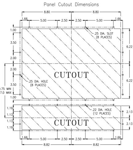
Note All units are in inches.
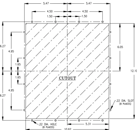
Figure 3-11 PanelMate Power Series 4000 Keypad Unit (Model 4200 -Split Architecture) Cutout and Torque Limits
17 INCH-POUNDS FOR #10-32 NUTS 7 INCH-POUNDS FOR #8-32 NUTS
Note All units are in inches.
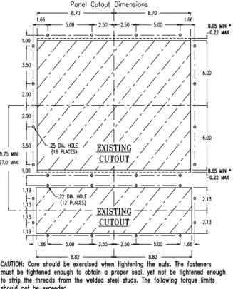
Figure 3-12 PanelMate Power Series 4000 Keypad Unit
(Model 4200 - Split Architecture) Cutout and Torque Limits for a PanelMate Series I, II, or III Cutout
Note To retrofit a PanelMate Power Series Keypad unit into an existing PanelMateSeries I, II, or III cutout, the cutout may need to be modified. If the existing cutout was made to the minimum dimensions for a PanelMate Series I, II, or III, then at least 0.050 inches should be removed from the front panel assembly before mounting the unit in the cutout. If the maximum of 0.22 inches is removed, the unit can be mounted without disassembly.
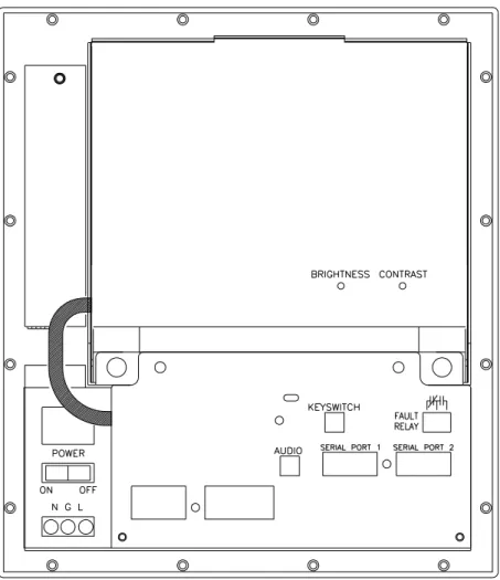
Figure 3-13 PanelMate Power Series 4000 Keypad Unit (Model 4200 - Split Architecture) Rear View
H-POSI H-SIZE BRIGHTNESS V-POSI V-SIZE CO NTRAST BRIGHTNESS O O O O O O O O ↔ ❐ ↕ ❏
Power Series 4000 Keypad unit using the following procedure:
1. At the back of the unit, remove AC power from the Electronics Module and the monitor. Disconnect any other cables.
2. Unplug the Monitor Module video cable from the Electronics Module. This cable disconnects the video signal to the monitor.
3. Remove the Monitor Module by turning the quarter-turn fasteners counter-clockwise. The Monitor Module is now disconnected and will slide out. Store in a safe location.
4. Remove the Electronics Module by turning the quarter-turn fasteners counter-clockwise. Support the weight of the assembly by holding the knurled fasteners, then gently pull the assembly toward you to disengage the front panel keypad connector. Then pivot the assembly to clear the mounting flange on the front panel. Store in a safe location.
5. From the front, insert the Front Panel in the cutout and fasten it with the eighteen #10 washers and nuts that are supplied with the unit.
Caution
6. Re-attach the Electronics Module by engaging the front slots of the Electronics Module on the mounting flange on the Front Panel. Raise the unit up to a horizontal position and slide the quarter-turn fasteners into their mounting holes on the front panel tray. Complete the assembly by turning the quarter-turn fasteners clockwise to lock in place.
7. Re-attach the Monitor Module. Slide the Monitor Module into the front panel tray and ensure the top lip overlaps the front panel lip. Turn the quarter-turn fastener clockwise to lock. Finally re-connect the video cable from the Monitor Module to the Electronics Module.
8. From the front, insert the keypad in the cutout and fasten it with the twelve #8 washers and nuts supplied with the unit.
9. You may now re-connect AC power to both the Monitor and Electronics Modules.
Exercise care when tightening the nuts. The fasteners must be tightened enough to obtain a proper seal, yet not be tightened enough to strip the threads from the welded steel studs. Do not exceed 17 inch-pounds.
versions are available: standard painted finish or stainless steel. The kit consists of a collar, mounting hardware, gasket, and a cutout/torque drawing.
To install the kit, first make the panel cutout for the mounting collar as shown in figure 3-22. Check to see if the mounting collar will fit, then remove. Attach the unit to the mounting collar with the 22 nuts and washers provided with the PanelMate Power Series 4000 (Split Architecture) Keypad unit Mounting Collar Kit.
Caution
Attach the gasket to the mounting collar. This is most easily done by placing the unit, with the collar attached, face down on a work surface. Take care to prevent scratching the front panel of the unit. Align the outside edge of the gasket even with the outside edge of the collar with the page edge facing the collar. Attach the gasket by stripping off a small section of the paper protecting the adhesive on the gasket. Carefully attach the gasket to the collar, uncovering the adhesive a few inches at a time. Insert the assembled collar in the panel and fasten the collar to the panel with 22 nuts and washers. Then, mount the front panel to the collar and then mount collar to the enclosure. Finally, attach the Monitor Module and Electronics Module.
Figure 3-14 PanelMate Power Series 4000 Keypad Unit (Model 4200-Split Architecture) Mounting Collar Assembly
Exercise care when tightening the nuts. They must be tightened enough to obtain a proper seal, but not tightened to the point where the threads are stripped or the gasket is rendered useless. Do not exceed 17 inch-pounds.
15.00 1.50 4.80 0.45 0.72 7.00 0.50 1.70 11.10 3.80 0.18 20.00 17.08 1.50 11.92 14.01
Figure 3-15 PanelMate Power Series 4000 Keypad Unit
(Model 4200-Split Architecture) With Collar Outline H-POSI H-SIZE BRIGHTNESS V-POSI V-SIZE CO NTRAST BRIGHTNESS O O O O O O O O ↔ ❐ ↕ ❏
Note All units are in inches.
Figure 3-16 PanelMate Power Series 4000 Keypad Unit
The PanelMate Power Series 4000 Keypad unit is designed to be used on the factory floor, mounted in an industrial enclosure. This section contains the information about installing the PanelMate Power Series 4000 Keypad unit in an enclosure and the installation of the various options that may be purchased. If you will be using any of the accessories, please refer to the sections of this chapter that provide specific information about each of the accessories before proceeding with installation. The instructions in this section are based on the assumption that you have already verified unit operation by performing the system health tests defined in Chapter 2.
Enclosure Sizing
Review the PanelMate Power Series 4000 Keypad unit Outline and the PanelMate Power Series 4000 Keypad unit Panel Cutout and Torque drawings shown on the following pages. Use this information to determine the enclosure size for your application. There are a number of factors to consider when selecting an enclosure in which to house the PanelMate Power Series 4000 unit. Although designed to
withstand harsh environmental conditions, you must not expose the unit to conditions which are beyond the detailed specifications found in Appendix A. Appendix B contains guidelines concerning enclosure sizing and temperature specifications taken from enclosure manufacturers.
To ensure proper convection cooling, we recommend a minimum 6-inch clearance above and 6-inch clearance below the unit when installed in an industrial enclosure.
Figure 3-17 PanelMate Power Series 4000 Keypad Unit (Model 4500) Outline H-POSI H-SIZE BRIGHTNESS V-POSI V-SIZE CO NTRAST BRIGHTNESS O O O O O O O O ↔ ❐ ↕ ❏
Note All units are in inches.
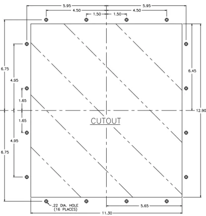
Figure 3-18 PanelMate Power Series 4000 Keypad Unit (Model 4500) Cutout and Torque Limits
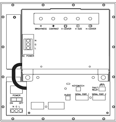
Figure 3-19 PanelMate Power Series 4000 Keypad Unit (Model 4500) Rear View
H-POSI H-SIZE BRIGHTNESS V-POSI V-SIZE CO NTRAST BRIGHTNESS O O O O O O O O ↔ ❐ ↕ ❏
Power Series 4000 Keypad unit using the following procedure:
1. Go to the back of the unit. Remove AC power from both the Electronics Module and the monitor. Disconnect any other cables.
2. Unplug the Monitor Module video cable from the Electronics Module. This cable disconnects the video signal to the monitor.
3. Remove the Monitor Module. Do this by turning the quarter-turn fasteners counter-clockwise. The Monitor Module is now disconnected and will slide out. Store in a safe location.
4. Remove the Electronics Module. Do this by turning the quarter-turn fasteners counter-clockwise. Support the weight of the assembly by holding the knurled fasteners, then gently pull the assembly toward you to disengage the front panel keypad connector. Then pivot the assembly to clear the mounting flange on the front panel. Store in a safe location.
5. From the front, insert the Front Panel in the cutout and fasten it with the eighteen #10 washers and nuts that are supplied with the unit.
Caution
6. Re-attach the Electronics Module. Do this by engaging the front slots of the Electronics Module on the mounting flange on the Front Panel. Raise the unit up to a horizontal position and slide the quarter-turn fasteners into their mounting holes on the front panel tray. Complete the assembly by turning the quarter-turn fasteners clockwise to lock in place.
7. Re-attach the Monitor Module. Slide the Monitor Module into the front panel tray and ensure the top lip overlaps the front panel lip. Turn the quarter-turn fastener clockwise to lock. Finally re-connect the video cable from the Monitor Module to the Electronics Module.
8. You may now re-connect AC power to both the Monitor and Electronics Modules.
Care must be exercised when tightening the nuts. The fasteners must be tightened enough to obtain a proper seal, yet not be tightened enough to strip the threads from the welded steel studs. Do not exceed 20 inch-pounds.
versions are available: standard painted finish or stainless steel. The kit consists of a collar, mounting hardware, gasket, and a cutout/torque drawing.
To install the kit, first make the panel cutout for the mounting collar as shown in figure 3-28. Check to see if the mounting collar will fit, then remove. Attach the unit to the mounting collar with the 22 nuts and washers provided with the PanelMate Power Series 4000 Keypad unit Mounting Collar Kit.
Caution
Attach the gasket to the mounting collar. This is most easily done by placing the unit, with the collar attached, face down on a work surface. Take care to prevent scratching the front panel of the unit. Align the outside edge of the gasket even with the outside edge of the collar with the page edge facing the collar. Attach the gasket by stripping off a small section of the paper protecting the adhesive on the gasket. Carefully attach the gasket to the collar, uncovering the adhesive a few inches at a time . Insert the assembled collar in the panel and fasten the collar to the panel with 22 nuts and washers. Mount the front panel to the collar and then mount collar to the enclosure. Finally, attach the Monitor Module and Electronics Module.
Figure 3-20 PanelMate Power Series 4000 Keypad Unit (Model 4500) Mounting Collar Assembly Care should be exercised
when tightening the nuts. The fasteners must be tightened enough to obtain a proper seal, but not tightened to the point where the threads are stripped or the gasket is rendered useless. Do not exceed 20 inch-pounds.
Figure 3-21 PanelMate Power Series 4000 Keypad Unit (Model 4500) with Collar Outline
H-POSI H-SIZE BRIGHTNESS V-POSI V-SIZE CO NTRAST BRIGHTNESS O O O O O O O O ↔ ❐ ↕ ❏
Note All units are in inches.
Figure 3-22 PanelMate Power Series 4000 Keypad Unit (Model 4500) Panel Mount Collar
(Model 5200-Split Architecture)
The PanelMate Power Series 5000 Keypad unit is designed to be used on the factory floor, mounted in an industrial enclosure. This section contains the information about installing the PanelMate Power Series 5000 Keypad unit in an enclosure and the installation of the various options which may be purchased. If you will be using any of the accessories, please refer to the sections of this chapter that provide specific information about each of the accessories before proceeding with installation. The instructions in this section are based on the assumption that you have already verified unit operation by performing the system health tests defined in Chapter 2.
Enclosure Sizing
Review the PanelMate Power Series 5000 Keypad unit Outline and Panel Cutout and Torque drawings shown on the following pages. Use this information to determine the enclosure size for your application. There are a number of factors to consider when selecting an enclosure in which to house the PanelMate Power Series 5000 unit. Although designed to withstand harsh environmental conditions, you must not expose the unit to conditions which are beyond the detailed specifications found in Appendix A. Appendix B contains guidelines concerning enclosure sizing and temperature specifications taken from enclosure manufacturers.
In order to ensure proper convection cooling, we recommend a minimum 6-inch clearance above and 6-inch clearance below the unit when installed in an industrial enclosure.
C A N C E L
Figure 3-23 PanelMate Power Series 5000 Keypad Unit (Model 5200-Split Architecture) Outline
Figure 3-24 PanelMate Power Series 5000 Keypad Unit
Figure 3-25 PanelMate Power Series 5000 Keypad Unit (Model 5200-Split Architecture) Side View
the PanelMate Power Series 5000 Keypad unit using the following procedure:
1. Go to the side of the unit. Remove AC power and disconnect any other cables. 2. Unplug the keypad connector from the Electronics Module. Make sure that you
do not pull on the keypad cable.
3. Remove the Electronics Display Assembly, turn the captive fasteners counter-clockwise. Support the weight of the assembly by holding the bottom of the unit, then gently tilt the top of the assembly and lift upward. Store in a safe location. 4. From the front, insert the Front Panel in the cutout and fasten it with the sixteen
#10 washers and nuts that are supplied with the unit. Make sure the cable does not get pinched between the enclosure and the Front Panel.
Caution
5. Re-attach the Electronics Display Assembly. Do this by engaging the front slots of the Electronics Display Assembly on the mounting flanges on the Front Panel. Raise the unit up to a horizontal position and slide the captive fasteners into their mounting holes on the front panel tray. Complete the assembly by turning the captive fasteners clockwise to lock in place.
6. Plug the keypad connector into the Electronics Module. Make sure you do not press on the keypad cable.
7. You may now re-connect AC power and cables. Be careful when tightening
the nuts. The fasteners must be tightened enough to obtain a proper seal, yet not be tightened enough to strip the threads from the welded steel studs. Do not exceed 17 inch-pounds.
floor, mounted in an industrial enclosure. This section contains the information about installing the PanelMate Power Series 5000 Keypad unit in an enclosure and the installation of the various options which may be purchased. If you will be using any of the accessories, please refer to the sections of this chapter that provide specific information about each of the accessories before proceeding with installation. The instructions in this section are based on the assumption that you have already verified unit operation by performing the system health tests defined in Chapter 2.
Enclosure Sizing
Review the PanelMate Power Series 5000 Keypad unit Outline and Panel Cutout and Torque drawings shown on the following pages. Use this information to determine the enclosure size for your application. There are a number of factors to consider when selecting an enclosure in which to house the PanelMate Power Series 5000 unit. Although designed to withstand harsh environmental conditions, you must not expose the unit to conditions which are beyond the detailed specifications found in Appendix A. Appendix B contains guidelines concerning enclosure sizing and temperature specifications taken from enclosure manufacturers.
In order to ensure proper convection cooling, we recommend a minimum 6-inch clearance above and 6-inch clearance below the unit when installed in an industrial enclosure.