Embedded Unit Testing Framework
Erik Bergersen
Master of Science in Computer Science Supervisor: Tor Stålhane, IDI
Co-supervisor: Øyvind Grotmol, Energy Micro
Department of Computer and Information Science Submission date: June 2013
Problem Description
The aim of this project is to make it easy to do thorough unit testing of C/C++ code writ-ten for the EFM32 microcontrollers, by creating a testing framework. The core problem is that the embedded code interacts with a number of peripherals on the microcontroller, which are not available when running the tests. Thus, it is essential to create mock objects or stub functions for all EFM32 modules, which allows the test instrumentation code to control exactly which response is given to the code-under-test (CUT), and also to capture the messages sent by the CUT in order to compare it with the expected behavior. The project will see if unit testing can reduce the number of errors before release of software, and that the work-hours used on testing can be reduced. Show that Unity and CMock is suitable as a framework for unit testing embedded software. The project will also look at problems and barriers that prevent developers from using unit testing during development of embedded software.
Abstract
This thesis addresses the challenges with unit testing of embedded software. Embedded software uses peripheral devices that are not available during testing, which results in higher barriers to use unit testing, compared to normal software. But even with these barriers there are no problems with unit testing of embedded software.
The study looks at challenges with unit testing of Energy Micros software library, and solutions to the problems with automated testing of embedded software. Use of automated testing will reduce the number of errors when code is refactored. Use of unit testing will also make it possible to take advantage of agile methods like test-driven development. The main goals for the study is to see if CMock is suitable for generation of mock modules and if testing with mock modules can reduce the number of errors in software.
Unity is a test harness that supports the needed assertions for testing of embedded soft-ware. CMock is able to automatic generate mock modules, but has a few problems with inline functions and custom types, but it is possible to solve these problems. Even with these problems CMock is able to generate mock modules that is working, and supports the testing of embedded software.
An experiment was performed to see if testing of embedded software with mock modules could reduce the number of errors. The result was significant and showed that the number of errors was reduced by using mock modules, compared development without testing. Observations were also done during the experiment, which found some problems with use of mock modules during testing. The experiment was done by undergraduate students in computer science.
Use of unit test and mock modules as a substitute for hardware during automated testing on a native computer, it is possible to reduce the numbers of errors and refactor code without breaking the existing functionality.
Sammendrag
Denne rapporten tar for seg utfordringene med enhetstesting av embedded programvare. Embedded programvare bruker perifere enheter som ikke er tilgjengelige under testing, dette resulterer i høyere barrierer for å bruke enhetstesting, sammenlignet med vanlig programvare. Men selv med disse barrierene er det ingen problemer med enhetstesting av embedded programvare.
Studien ser på utfordringer knyttet til enhetstesting av Energy Micros programvarebib-liotek, og løsninger på problemer med automatisk testing av embedded programvare. Bruk av automatisert testing vil redusere antall feil etter refaktorering av kildekoden. Bruk av enhetstesting vil også gjøre det mulig å ta i bruk smidig utvikling, som for eksempel test-drevet utvikling. Hovedmålene for studien er å se om CMock er egnet som et rammeverk for generering av mock moduler og om testing med mock moduler kan redusere antall feil i programvaren.
Unity er et testrammeverk som støtter de nødvendige sammenligner under testing av embedded programvare. CMock er i stand til å automatisk generere mock moduler, men har problemer med ‘’inline” funksjoner og håndtering av strukturer og andre ikke primitive datatyper, men det er mulig å løse disse problemene. Sett bort fra disse problemene er CMock i stand til å generere mock moduler som fungere og kan støtte testingen av embedded programvare.
Et eksperiment ble utført for å se om testing av embedded programvare med mock moduler kunne redusere antall feil. Resultatet av eksperimentet var statistisk signifikant og viste at antall feil vil bli redusert ved bruk av mock moduler, sammenlignet med utvikling uten testing. Observasjon ble også gjort under forsøket, dette oppdaget noen problemer ved bruk av mock moduler under testing. Eksperimentet ble utført av studenter ved datateknikk.
Ved å bruke enhetstester og mock moduler når hardware ikke er tilgjengelig for automatisk testing på vanlig datamaskin, er det mulig å redusere antall feil og refaktorere kode uten å ødelegge eksisterende funksjonalitet i programvaren.
PREFACE
The report was written as final thesis for the master degree in computer science at Nor-wegian University of Science and Technology (NTNU). The thesis was carried out in the spring of 2013 and looked at unit testing for embedded software.
The aim for the project is to do easy unit testing of C/C++ code, which are written for EFM microcontroller, by studying Unity and CMock as unit test framework for embedded software. The project was given by Øyvind Grotmol at Energy Micro.
I would like to thank my supervisor Tor Stålhane for his continuous input and guidance during the project. I would also like to thank Øyvind Grotmol and Marius Grannæs at Energy Micro for the help during the project. I appreciate that XCOM14 could get participants to my experiment.
Trondheim, June 10, 2013
CONTENTS
Preface i
Contents iii
List of Figures vii
List of Tables ix 1 Introduction 1 1.1 Problem Definition . . . 1 1.2 Motivation . . . 1 1.3 Goals . . . 2 1.4 Approach . . . 2 1.5 Outline . . . 3 2 Background 5 2.1 EFM32 . . . 5 2.2 Unit Testing . . . 9
2.3 Testing of Embedded Systems . . . 12
2.4 Existing Code . . . 16
3 Embedded Unit Test Framework 19 3.1 Introduction . . . 19
3.2 Dependencies . . . 20
3.3 Software . . . 22
3.4 Testing of Peripherals . . . 25
3.6 Testing of Examples . . . 34
3.7 Testing of Drivers . . . 41
3.8 Automated Build System . . . 42
3.9 Summary . . . 45
4 Experiment 47 4.1 Definition . . . 47
4.2 Planning . . . 49
4.3 Operation . . . 52
4.4 Analysis & Interpretation . . . 54
4.5 Summary . . . 63 5 Discussion 65 5.1 Experiment . . . 65 5.2 Mock Modules . . . 66 5.3 Embedded Testing . . . 68 5.4 Test Strategy . . . 69
5.5 Agile Development and Test-driven Development . . . 70
5.6 Regression Testing . . . 71 6 Conclusion 73 6.1 Conclusion . . . 73 6.2 Further Work . . . 74 Bibliography 75 Abbreviations 77 A Experiment Guidelines 79 A.1 Introduction . . . 79 A.2 Instruction . . . 79 A.3 Tasks . . . 83
A.4 When Finished . . . 91
B Experiment Test Cases 93 B.1 Task 1 . . . 93
B.2 Task 2 . . . 95
B.3 Task 3 . . . 97
B.5 Task 5 . . . 101
C Mock Preperation Script 103
C.1 Script . . . 103 C.2 Config-file . . . 106
LIST OF FIGURES
2.1 Bit-banding . . . 7
2.2 Software Layers . . . 7
2.3 TDD State Machine [16] . . . 11
3.1 Blink Dependecies . . . 21
3.2 Blink Dependecies with Mock Modules . . . 21
3.3 STK3700 Hardware Layout [12] . . . 35
4.1 Boxplot of Test Results . . . 55
4.2 Distribution of Errors . . . 55
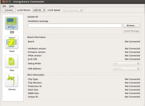
A.1 Connect with energyAware Commander . . . 81
A.2 Upload with energyAware Commander . . . 81
A.3 STK3700 Hardware Layout [12] . . . 82
LIST OF TABLES
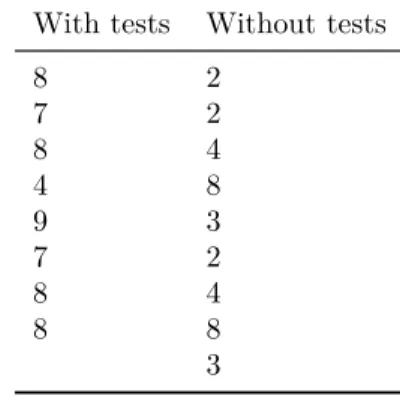
4.1 Errors per Participant . . . 54
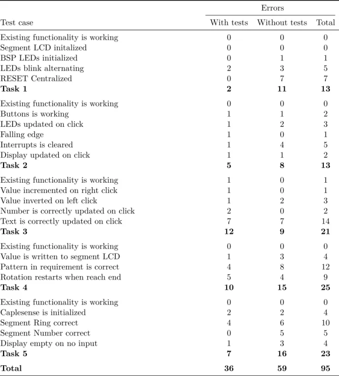
4.2 Errors per Test Case . . . 56
4.3 T-test Results . . . 62 B.1 Test case TC1-1 . . . 93 B.2 Test case TC1-2 . . . 93 B.3 Test case TC1-3 . . . 94 B.4 Test case TC1-4 . . . 94 B.5 Test case TC1-5 . . . 94 B.6 Test case TC2-1 . . . 95 B.7 Test case TC2-2 . . . 95 B.8 Test case TC2-3 . . . 96 B.9 Test case TC2-4 . . . 96 B.10 Test case TC2-5 . . . 96 B.11 Test case TC2-6 . . . 97 B.12 Test case TC3-1 . . . 97 B.13 Test case TC3-2 . . . 98 B.14 Test case TC3-3 . . . 98 B.15 Test case TC3-4 . . . 98 B.16 Test case TC3-5 . . . 99 B.17 Test case TC4-1 . . . 99 B.18 Test case TC4-2 . . . 100 B.19 Test case TC4-3 . . . 100 B.20 Test case TC4-4 . . . 100 B.21 Test case TC5-1 . . . 101
B.22 Test case TC5-2 . . . 101
B.23 Test case TC5-3 . . . 102
B.24 Test case TC5-4 . . . 102
CHAPTER
1
INTRODUCTION
This chapter is an introduction to the thesis. The chapter contains; problem definition, motivation, context and an outline of the report.
1.1
Problem Definition
The task was given by Øyvind Grotmol in Energy Micro. The project’s aim is to look at an embedded unit test framework, which make it easy to do unit testing of C/C++ code. This code is written for Energy Micros microcontrollers. The company needs a unit test framework to take advantage of agile methods during development of example projects for Energy Micros development kits, and development of the software library for the microcontrollers.
One problem with unit testing in the embedded space is that the code interacts with peripherals on the microcontroller that not can be accessed during tests. To be able to test this logic there is a need to create stub functions and mock objects that make it possible to test instrumentation code to check which response is given during the test, and to capture the messages in order to compare it with the expected behavior.
The thesis will look at different layers of the software library that Energy Micro provides, with focus on the examples that are provided for the different development boards.
1.2
Motivation
The motivation for solving this problem is that Energy Micro has more than 200 example projects, which is available for the users of theirs starter and development kits. Energy Micro has nine different development boards. Many of the examples support several of these development boards, in addition they have to support four different IDEs (Integrated Development Environment). The problem with testing is caused by the development boards and more than 200 example projects. In total this will be more than thousand binaries, which is a huge amount of binaries to test if changes are made in the software libraries. Testing can be supported with unit tests that are run automatically, instead of
manual system tests, which would be very expensive.
1.2.1
Purpose
The purpose of the thesis is to find methods that can be used to reduce the number of errors that are created during refactoring and modification of code. By using unit testing it is also possible to adopt agile methods like test-driven development. If more of the tests activities can be automated, time used on testing can be reduced.
Use of mock modules/objects will be essential in thesis, since interaction with hardware is not possible during running of tests on a host computer.
The objectives of the thesis is to verify that Unity and CMock is suitable as a unit test framework for embedded systems and to see if unit testing can work as a method for regression testing of a software library for several different microcontrollers.
1.3
Goals
For the project there are both research goals and goals that Energy Micro has for testing their library with unit testing.
The research goals for the project are as follow:
RQ1 Is it possible to reduce the number of errors during development of new features, modification and refactoring of existing functionality by using mock modules to verify the desired behavior of the system?
RQ2 Show that CMock is a suitable framework to create mock objects, which can simu-late the behavior of the hardware, which is not available during testing on a native system.
The goals for Energy Micro are:
1. Reduce the number of errors in the code, before releasing it to the customers. 2. Take advantage of agile development, with unit testing and test-driven development. 3. Be able to refactor or change the code on a later time, without breaking the code. The first of the goals is connected with RQ1, since they both look at the reduction of errors. The second goal is accomplished if Unity and CMock is suitable for testing. The last goal is fulfilled if the framework can be used to create tests, which can be run automatic on a host computer, for the code that is changed.
1.4
Approach
The thesis consists of two parts, where the first is to use the test framework in practice to test functionality in the software library. The second part will be an experiment where we look at how mock modules can reduce the number of errors during development.
To be able to use a unit test framework to perform regression testing on a software library that supports about a hundred different microcontrollers, we need to look at advantages and disadvantages of this solution. Testing of peripherals, kit specific code and example projects will be done to find barriers and challenges with unit testing, in order to find a solution. When testing a software library for microcontrollers, it is impossible to test all the code, since it will depend on hardware. The focus will be on the mock modules created by CMock, since this is an important tool to be able to solve the tasks, when hardware is not available under testing.
The experiment will be used to study the reduction of errors when the developers use unit tests based on mock modules to add new features to the system, and under modification of existing features. The participants in the experiment will implement features in a few tasks that are based on examples for the Energy Micro Giant Gecko STK3700 Starter Kit.
1.5
Outline
Background gives background information about hardware, software and techniques that is used in the thesis.
Embedded Unit Test Framework summarizes testing of the Energy Micro software libraries, and looks at challenges and solutions by using unit testing to perform regression testing.
Experiment contains the experiment that was performed during the thesis, which in-cludes the definition, planning, operation, analysis & interpretation and conclusion.
Discussion contains the discussion of the results from the testing and the experiment, and a comparison of these two parts.
Conclusion contains the conclusion, together with further work.
Appendix contains guidelines for the experiment, and the test case used for measure-ment in the experimeasure-ment. It also contains source code, tests and scripts as documen-tation when needed as a reference for other parts of the report.
CHAPTER
2
BACKGROUND
This chapter describes some of the hardware features that are available on the EFM32 microcontroller. The chapter also includes some unit testing theory, how testing is per-formed on embedded systems/software and a part on how to write tests for code without tests.
2.1
EFM32
This section gives a short introduction to the EFM32 microcontroller family developed by Energy Micro, the ARM Cortex-M processor and a short description of a few periph-erals that are included on the microcontroller. It also includes a short description of the development boards that are produced by Energy Micro, the support for IDEs and description of the parts in the software library that are provided for development on the microcontrollers.
2.1.1
Energy Micro
Energy Micro is a Norwegian company that was founded in 2007. Energy Micro develops the EFR (Energy Friendly Radios) family and EFM (Energy Friendly Microcontrollers) based on ARM Cortex processors [5]. The focus for the company is to provide microcon-trollers with low energy usage. This project will focus on the embedded unit testing of the software for the microcontrollers.
2.1.2
Hardware
The main part of the hardware in this project is the microcontroller, which is based on an ARM processor. In addition there exists several peripheral devices, and hardware features that are available on the development boards.
Microcontroller
A microcontroller consists of an on-board memory unit, a microprocessor and I/O devices, and it is designed for low-cost systems [24]. The EFM32 microcontrollers are delivered with different amount of RAM and flash memory, different peripherals and different pack-ages. All EFM32 microcontrollers use the ARM Cortex-M3 microprocessor.
ARM Cortex-M3
The Cortex-M processor is the processor that is used in the EFM microcontrollers. The Cortex-M processor architecture is created by ARM, and is made for ”tomorrows embed-ded applications” [1]. It is designed to be energy efficient, and uses a processor built on the RISC architecture.
Peripherals
The EFM32 microcontrollers have several peripheral devices. The microcontrollers use the peripherals for input, output and storage. The peripherals on the microcontroller are designed for energy efficiency. Below is a list of some of the peripheral device that is available on the EFM32 microcontrollers:
ACMP The Analog Comparator (ACMP) is a module that compares analog signals and gives a digital voltage to indicate which of the analog signal that is highest.
ADC The Analog to Digital Converter (ADC) is used to convert analog signal to a digital signal. The peripheral can give a digital output with a resolution of 12 bits. The input can be selected from 6 internal signals and 8 external pins [11].
AES Advanced Encryption Standard (AES) is a peripheral for encryption and decrypt-ing. The module supports 128 and 256-bits encryption [11]. The hardware module uses considerable less energy, than what a software implementation would use.
UART Universal Asynchronous Receiver/Transmitter (UART) is a serial IO peripheral, which support full duplex and half duplex communication.
LCD This peripheral is used to drive the segmented Liquid Crystal Display (LCD). The LCD can for example be used to display text.
Watchdog The purpose of the watchdog timer is to reset the system to a known state if it encounters a system failure. The watchdog has a timer with a configurable period that is the timeout threshold. The timer will count continuously with the signals given from an oscillator. The processor must feed the watchdog with a reset signal before timeout.
Bit-banding
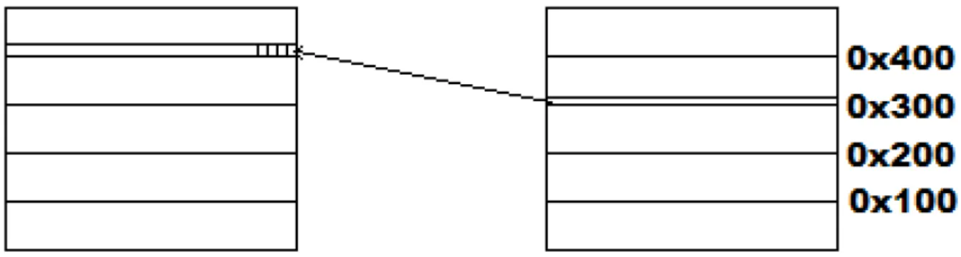
Bit-banding is a technique that is used to map words to bits. This is done since writing to a single bit will require reading the word, modify and then write the bit back. By using bit-banding, it is possible to do this in a single operation [11, p. 16]. Figure 2.1 illustrates bit-banding.
Figure 2.1: Bit-banding
2.1.3
Software libray
The software library that is delivered by Energy Micro consists of several layers as seen in Figure 2.2. Each of these layers is described below.
Figure 2.2: Software Layers
Cortex abstraction layer CMSIS (Cortex Microcontroller Software Interface Standard) is a hardware abstraction layer for the ARM Cortex-M processors. This layer is in-dependent of the microcontroller and provides an interface to the ARM processor architecture.
CMSIS peripheral support library This layer consists mainly of memory registers definitions and bit field definitions. The layer does not include any functionality that can be tested. Each microcontroller has different specifications in this layer, depending on the availability of memory and peripheral devices on the microcon-troller. The support layer also includes a system layer for the microcontroller on the ARM Cortex-M3.
Energy Micro peripheral library This layer is a HAL (Hardware Abstraction Layer) and an API (Application Programming Interface) for each of the peripherals, and has little logic. The peripherals will be tested later in this thesis, to look at possi-bilities and problems with testing on this layer. This layer is used by every micro-controller, where the CMSIS peripheral support library defines the ability for the given microcontroller. Although this layer has little logic, unit tests will be needed,
because these are necessary for regression testing, and for testing with test-driven development.
Board support package This is a support package for the starter/development kit, which includes support functions and communication package definitions for the kit. The board support package also includes drivers and examples that are described below. Each starter/development kit has its own board support package. It may be necessary to unit test some of the functionality of the board support functions.
Device drivers The drivers are used to demonstrate functionality on the development board. The device drivers are created for several starter and development kit, and configuration is used to specify them for each kit. Examples of drivers are segmented display driver and NAND flash driver. Unit testing of the device drivers is necessary, and it can be tested on the development board, or with use of mock objects.
Examples The examples are given as a quick start to programming on the development boards. The examples demonstrate functionality that the development board has. Each of the kits has 10 - 50 different examples. Some of the examples exist on several of the kits, but they are different due to hardware and memory differences. Most of the examples support four IDEs. Some of the examples will be tested later in the thesis.
2.1.4
Integrated development environment
Energy Micro support four IDEs (Integrated Development Environment) [12]. The sup-port gives the ability to open example projects in the given IDE. The IDEs that are supported are:
• IAR Embedded Workbench for ARM • Rowley Associates - CrossWorks for ARM • CodeSourcery - Sourcery G++
• Keil - MDK-ARM
When compiling and building, each of the IDEs will create a binary, which will result in four binaries for an example. This raises the complexity with testing due to the amount of binaries that will need testing. Compiling each example for all the IDEs is necessary, since the IDEs uses different compilers. The C programming language standard specifies the language, but it does not specify behavior in all cases, the language has cases of undefined behavior1, implementation-defined behavior2 and unspecified behavior3. It is
thus necessary to compile and test on all IDEs/compilers.
1behavior, upon use of a nonportable or erroneous program construct or of erroneous data, for which
this International Standard imposes no requirements [17, 3.4.3]
2Unspecified behavior where each implementation documents how the choice is made [17, 3.4.1] 3use of an unspecified value, or other behavior where this International Standard provides two or more
2.1.5
Development boards
Energy Micro has several kits that can be used by developers to test and debug the EFM microcontrollers. Energy Micro provides two types of kits; development kits and starter kits. The starter kits are simple kits that can be used to try out some of the features in the microcontrollers. These kits are mostly an evaluation of the microcontroller. The developer kits are made for advanced users that want to develop embedded systems. The developer consists normally of more functionality and more advanced features than the starter kits, and has better support to build custom circuits. With the advanced energy monitor, the users are able to see the energy usage on the system, and are able to evaluate and debug with the developer kit. With tools to monitor energy usage, the developers are able to optimize their system, to use as little energy as possible. The starter and developer kits differ for each microcontroller family developed by Energy Micro.
2.2
Unit Testing
This section gives an introduction to unit testing, description of a few test doubles and a description of test-driven development.
2.2.1
Unit testing
Unit testing is a technique for white box testing, where the testers now the internal structure of the system. Unit testing is about breaking the code down to small units of code, a unit could be a single method in the code or a complete class (object-oriented programming). Test cases are written to verify the correct behavior of a unit, and the test cases are independent of each other. To be able to do unit testing, the developers will normally need a test harness, which will include functionality to do assertions, setup for test and afterwards clean-up after the test. In addition they normally have some functionality for test report.
When unit testing, some part of the system may not be available, because it needs hard-ware that is not available during testing, functionality that not are fully developed yet or using functionality like network or databases that will result in that tests uses too long time to finish. For these parts it could be necessary to use mock objects, test stubs or other test doubles to simulate and be able to run the tests. The benefits of using unit tests are that it is possible to test and find errors early in the process, and it can be used to check that code is not broken during changes or refactoring of the code. Unit tests itself is documentation that the code is tested and should behave like the developers intended. Using unit testing during development on embedded system will reduce the number of times it is necessary to compile the code for the hardware, upload it and then run the tests on the hardware. During testing with unit tests it is important that the code is testable, by structuring the code so only one layer do access the hardware, which will improve the design of the software. When a problem is identified it is easier to fix errors that are discovered by the tests, than having to debug on the hardware. This will reduce the amount of work-hours the developers use. During development of hardware that is not ready for production, it is possible to start implementation of software and test it using unit test and mock objects, before the hardware is ready, which mean that development
can start early in the process.
2.2.2
Test doubles
During testing of code, several collaborators are working together, like methods, classes, data and modules. The unit that is tested with a unit test depends on several of these collaborators. A test double represents and acts like a method, class, data or module [16]. There exist many kinds of test doubles; this part will only look at stubs, fakes and mock objects.
Stubs
A stub is a function that is created to only return a value, without any functionality. Similar to a test dummy, that is a function that only is created to be able to compile/link an application [16].
Fakes
A fake object is an object that is used to break dependencies during testing. A fake is a collaborator that acts as an object or a module during testing [15]. The fake has implemented some functionality, but is not fully implemented, since the main purpose is to break the dependency. The fake can be used to break the dependency to for example hardware, which will make it possible to run the test without hardware. The fake will never be able to detect any errors, but will act as a collaborator that may simulate some form of behavior.
Mock objects
A mock object is an advanced version of a fake module/object. The difference is that the mock object/module uses internal assertions [15]. When using the mock objects, the developers sets the expectations and inject return values before the unit tests are run, afterwards the expectations are verified. The verification in mock object will check that the method is called and will verify the parameters with assertions. The mock module will also verify that the method is called the right number of times. It can also verify that function calls are done in the correct order.
When using unit testing, it is necessary to use objects and modules that can behave like components that are not ready for testing or is not available during automated unit testing, for example hardware. The mock object can be used to describe the call between modules, and the expected parameters and return values [16].
The programming language that is used for the embedded software in this thesis is C. Since C is not an object-oriented language, mock object will be referred to as mock modules instead.
2.2.3
Test-driven development
TDD (Test-driven development) is a software development process. The purpose is to ensure that all code that is written is being tested. The main idea is that you write code if you have a failing test, and a cycle in the development is finished when all the tests are passing. A cycle in test-driven development is commonly known as red-green-refactor [16]. This means that you first write a test that is failing, the reason why it is failing should be a compilation error, because the compiler cannot find the definition of the function the test is calling. The developer should then fix this error by adding a stub function, run the tests to verify that they are green. Then the tests should be changed so it asserts values for different input values. When the code is red again the feature can be fully implemented. When the tests are run again they should be green and the developers are able to refactor the code, if it is needed. When using this TDD cycle, it will be possible to discover and eliminate bugs early. Figure 2.3 [16] display a state machine to describe how test-driven development is used in C programming.
Figure 2.3: TDD State Machine [16]
When using a process like TDD during development on an embedded system, the de-velopers will have to write code that is intended to run on two different systems; the development system and the hardware that will be used for production. With this ready the developers can run tests during development, which will be used to verify that the production code is correct without the need of an embedded device.
2.2.4
TDD for embedded software
It is possible to use test-driven development for embedded systems. Each time new functionality is created, a test will be created for this function. When functionality is refactored, modified or functionality added, the unit tests can check that the functionality that existed before modification is still working afterwards. This can be used as automated
regression testing of the software. To ensure that a system with low number of errors are delivered, system tests will still be necessary, but with the automated regression tests, the time that will be needed to use for system and acceptance testing will be reduced. Since one of goals is to take advantage of agile methods, test-driven development is a good suggestion. TDD can also be used together with other agile methods like Scrum or Extreme Programming.
Test-driven development is a method that will help to ensure that the software is well-tested, which can be used to find errors in the hardware. These errors can be found since well-tested software often are easier to understand, and confidence with that code is well-tested, will prevent the developer from starting extensive debugging, because the developer thinks the error is within the software. In ”Effective Test Driven Development for Embedded Software” [18] there is suggested a four level strategy, the first level is automated unit testing and for each level more human interaction is necessary. The levels described are:
Automated unit testing Unit tests are added during development, and mock objects generated when needed. The mock can be generated in a MCH design pattern to be able to decouple the logic from hardware. The automated unit tests are run by the developer. The tests are run on development boards, emulators or as cross compiled tests on a computer. The tests can also be automatic tested by a continuous integration tool.
Hardware level testing A combination of unit testing and interaction by the tester is used to test user interaction and hardware. The most important part of this testing is the hardware functionality [18]. These tests will be run infrequently compared to automated unit testing.
Communication channel testing Use developer tools to capture test results from the embedded device. Both hardware and software will be tested, and it will require interaction from the testers to create communication events during testing.
End to end system testing This layer executes the scenario tests, which is to test the user scenarios that are defined for the system. Important things to test are timing issues, user interface and the responsiveness of the system.
2.3
Testing of Embedded Systems
This section will briefly look at unit testing on embedded systems, and how system testing can be done for software and hardware.
2.3.1
Hardware testing
Testing of embedded software is in many ways different from regular software for personal computers. Some of the differences are the architecture, platform, processing speed, mem-ory available and storage capacity. Debugging is also different, on software for computers, debugging can be done through the IDE. For embedded systems there will be a need for a development board with a debugging interface, for example JTAG, which can be used
for example for single stepping and break pointing when debugging on the embedded device. JTAG was developed as a test interface, but is also widely used as an interface for embedded debugging [22]. When testing embedded software, testing must cover both hardware and software, since errors can exists in both or in a combination of them. In “Effective test driven development for embedded software” [18], three methods of test-ing is described: ad-hoc testtest-ing, debuggtest-ing and final testtest-ing. The article describes the current state of these and the shortcomings with the three methods, when testing on embedded systems.
Ad-hoc testing and experimentation is often used during development to discover infre-quent cases in the system, usually to test system boundaries. The knowledge that is gained from such testing and experimentation during implementation of the functional code will usually be discarded or shelved. So later in the development process this knowl-edge is lost, and work-hours will be used later during development, due to the fact that tests are not kept updated [18].
Since errors can come from both hardware and software, embedded software uses many debugging and inspection tools during development. There exist many advanced debug-ging tools for embedded systems. The effect of these tools has however, some bad side effects. The use of debugging tools can result in that the software is designed for debug-ging and not for testability. Finding errors with debugdebug-ging is difficult, since it is unknown where the error is. Debugging to find a specific error is something that is done once, it is not necessary to design the code for debugging when the errors is found and corrected. When using debugging widely to test and develop, it will often result in bad coding prac-tices, because the code is not designed to be testable, so hardware and software is not decoupled [18]. A positive effect with debugging is that it can be used to find errors, when developers not able to understand the results from a given input. Another weakness is that test equipment for microcontroller can be expensive, so it will be impossible for low budget projects [14].
Development processes like waterfall are often used during development of embedded software systems. The process starts with a design of the system, then development of the system, testing of the system and finally production. Testing is a costly stage of the development and it is difficult to find the correct point for when the testing is finished and the system is ready for production. Since testing is one of the last stages, testing can be reduced for projects that are delayed and need to meet a deadline. The result will be that the system is not tested well enough and can contain critical errors. When testing is done late in development, there is a chance that the code is not designed and developed for easy testing [18].
2.3.2
Unit testing
There exist several unit test frameworks created for testing of embedded software. There are different ways in which unit tests can be used to test embedded software. “Function-ality and Design of the CMock framework” [20] lists three common soultions:
• A development board or a development kit as described in the preliminary study chapter can be used for automated testing of the embedded software. The test binary is deployed on the development board and then executed, the results from
the tests are written to a memory location or transferred back to the computer through a debugging interface. Testing on a development board is a slow method since it requires deployment to the development board, and the embedded system usually has a processor that is much slower than a normal computer. The big advantage is that the test is run with access to the peripheral devices.
• An emulator that can be used to simulate the behavior of the hardware. The advantage from the development board is that the emulator is much faster, but like the development board it will need a debugging interface to transfer the results from the tests. A debugging interface is not necessary a feature that is provided by the emulator and the support for peripheral is not always available, or is only partially implemented.
• The last solution is to run the tests on the local computer. This is the fastest solution. But the tests have no access to peripheral devices and real hardware. To be able to test with usage of a peripheral device, there is a need to develop mock objects and stub functions to simulate the behavior, but the results may not be the same as on the embedded device. There might be problems with the compatibility between the embedded device and the local computer, since the platforms are different and uses for example different sizes on data types.
2.3.3
System testing
System testing looks at testing at all the stages in the development of an embedded system.
Hiearchy of testing
”Testing Complex and Embedded Systems” [19] explains a bottom to the top hierarchy of testing software for embedded software. The different levels of testing are described below:
Unit Testing This is testing of the smallest units of software. This level includes build tests and regressions tests, where the build tests is responsible for testing the func-tionality that was changed, and regression test is run to verify that no other software components was affected by the changes in the code.
Component Testing Is testing on a higher level, where tests are focused on the com-ponents instead of the units.
Integration Testing Test the integration of software and hardware, to test interaction and that the systems behavior is as intended.
System Testing This is integration of the subsystems, which includes multiple hard-ware and softhard-ware components. Some suggested system level options are: FAT (Factory acceptance testing), OT (Operational testing) and MQT (Manufacturing qualification testing).
Field Testing Testing of software in real environments, the system is complete and is tested as it would be used in real-life.
Simulation and emulation
The goals of simulation are to derive requirements and find unknown interactions and details in the system design [19]. The simulation is often a model of a function or process. The requirements that are derived are used to create the tests that are needed in the development process.
Emulation is different from the simulation, since an emulator is a replica of software/hard-ware that is used for debugging and testing [19].
Model to final product
Development of embedded software needs many test activities, during the different stages of the process. In ”Testing embedded software” [13] a process is described for building embedded systems in stages. These stages are simulation, prototyping, pre-production and post-development.
When the requirements for a system are finished, a simulation model is created to ver-ify requirements and to optimize the system design. The simulation is usually run in dedicated software tools to simulate the model [13]. The simulation is executed in three stages.
• One-way simulation: Testing of the system in isolation, where only one input is tested at a time. Tools are used to generate input to the model.
• Feedback simulation: Testing the interaction between different parts in the system. Initially the system should be simulated only with needed parts, environments is not part of this simulation.
• Rapid prototyping: Testing of the system with a real environment. This is done by connecting the model to the real environment by connecting the computer to actuators and sensors.
The second stage in the process is to release a unit for pre-production, and validate the model used in simulation. The model is incrementally replaced with real hardware and software. The prototype is run on either the real hardware or with an emulator on a host computer. This stage consists of several test levels; software unit testing, software integration testing, hardware integration testing and environmental testing [13]. For each of the levels the software, processor, hardware and the environment is gradually replaced from simulation to experimental prototype to the target.
The goals of the pre-production stage are to verify that all requirements are implemented and the system is working as expected. The system is tested with real hardware and software in a real environment. Examples of test techniques that can be used are real-life testing, random testing and fault injection [13]. Examples of test types in this stage are acceptance tests and safety execution tests [13].
The previous stages have made the system ready for production. The post-production testing ensures that production facilities have high enough quality. The stage is based on development, testing and inspection of production facilities.
2.4
Existing Code
Adding unit tests to existing code that is without tests and not designed for testing can be difficult. For Energy Micro’s software there exist only a few tests, which mean that starting to use agile methods like test-driven development may be difficult, and since only a few tests exist there is also a chance that the code is not designed for testability. The ability for testing is important to able to use unit tests and by having unit tests, these can be used as regression testing when software is changed.
2.4.1
Why change software?
There is four reasons for changing software; adding a new feature, fixing an error, im-provement of the design and optimize the performance [15].
Adding a new feature is one of the most common reasons to change software, and when adding new features these should always be tested by unit testing. A new feature can be both changing and adding of behavior, which would result in a need to test dependencies. Testing is important when fixing an error. If there already is a test for this code unit, the test should be changed so it tests the wanted behavior of the function. If not, we should write a test to be able to test the corrections that are done in the code, and to be able to execute regression tests later.
Improvement of the design can result in that features are lost and result in an error. When design is improved without losing behavior it is called refactoring [15]. To be able to do structural changes there is a need to have unit test to perform regression testing. When the structure is changed in the code, there may be need to change existing tests.
Improving the performance of code is like improving design, but the goals is not the same. When algorithm is changed or the structure is changed to optimize the code, it is important to have tests to be able to do regression testing, to ensure that behavior of the code is not changed.
2.4.2
Dependencies
When working with code, dependencies to other libraries and functionality is one of the biggest barriers for testing. When unit testing, you want to use units that are as small as possible, the unit’s dependencies can results in many interactions or interaction with functionality that is not available under tests, like hardware. To be able to test a unit you do not want to make any changes to the code, so it is necessary to look for seams in the code. A seam is to change the behavior of the program, without doing any changes in the code you want to test [15]. In C programming there is two good ways to do this. One of the solutions is to do the modifications of the programs in the preprocessor. The preprocessor can be used to define variables and add addition behavior. It is also possible to use macros to change existing parts of the code. In chapter 3, a macro is used to change the Delay() method, so delays do not occur in the loop during testing.
By using static linking it is possible to link other libraries or functions during the linking part of compilation. This can be done with the mock modules that are generated with CMock. Instead of using the actual module, the mock module is linked to create the test
binary.
2.4.3
TDD with existing code
Starting to use test-driven development with existing code without tests, can be a problem to find where to start. In “Test-driven development for embedded C” [16], a policy for adapting test-driven development is suggested for a team that has code without tests:
• For new code, use test-driven development.
• Before modifying the code, add tests for the existing code. • Test the code after modification.
The first point states that when new functionality is developed, the development will follow the default cycle of test-driven development, where the cycle starts with a failing test. The second point suggests that tests for the existing code must be written before any modification is done to the code. When tests have been added, the code can be modified to support new functionality. After modification the tests can be run. After this modification, more of the source code is covered by unit tested and the developers have tested both new and modified code with unit tests. The goal when using TDD on existing code should be to get the module that is changed under test.
CHAPTER
3
EMBEDDED UNIT TEST FRAMEWORK
This chapter discusses possible solutions for testing embedded software. Energy Micros software library consists of different layers, but the most important part is testing of examples projects that are delivered to the development boards.
3.1
Introduction
The purpose of testing the software library is to look at problems with unit testing of a software library for more than hundred microcontrollers, and to find solution to these problems. This chapter will also look at how suitable Unity and CMock is for testing a library like this. If a sufficient part of the software library can be unit tested, it is possible to use these tests for regression testing, since regression testing of the software library is impossible with more than a hundred microcontrollers after a modification in the library. The section will mostly focus on software unit testing, but in some parts also look at software integration testing and integration testing. In addition it will be necessary to see if the examples for each of the kit can be tested with unit tests.
To be able to run tests that supports different microcontrollers, it will be necessary to look at an automatic build system to make testing easier and reduce the number of tests that are run after each modification, Ceedling is a tool that will be looked into here.
3.1.1
Testing of the software library
The layers that will be looked at during testing are the examples, device drivers, board support package and the Energy Micro peripheral library. Testing of the examples and drivers is the most important, because most of logic is placed in these layers.
There will be not testing of the Cortex Abstraction Layer, since this layer should be tested with access to hardware. The CMSIS Peripheral Support Library will not be tested since it mainly consists of definitions of memory registers and bit fields.
3.1.2
Literature
To be able to solve problems that occur during testing, two books have been used to find ideas for how to solve the problems. During testing of software, different problems will be discovered, and it might be possible that the solution of the problem can be found in these books. The two books are listed below:
• ”Test Driven Development for Embedded C” by James W. Greening [16]. • ”Embedded Testing with Unity and CMock” by Mark VanderVoord [21].
3.2
Dependencies
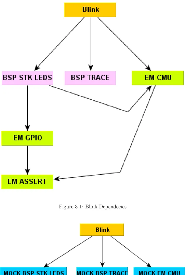
Dependencies to other modules and libraries are one of the barriers to unit testing. Dur-ing unit testDur-ing the tester wants to test the functionality for the given unit, and is not interested in the effects of the dependencies. Testing with all the dependencies will re-sults in slow tests because they test much more functionality than the actual unit, and the functionality will be tested over and over again. Dependency injection is one way to solve this, but we will need a structure of the code for these, and the method is mostly used in object-oriented languages. Stub functions, fakes and mock modules can be used for this during testing, where these is modules is set by static linking or use of macros. Below follows an example over the dependencies for the blink example. Figure 3.1 shows the dependencies for the simplest example, which is blink. Blink is actually only a tem-plate to start developing on the starter kit. The figure shows the dependencies to other modules, but it does not include inline methods that are defined in other header-files, which also are dependencies. If the inline functions were added there would be at least dependencies to the bit-banding peripheral and the device peripheral.
Figure 3.1 shows that the blink example needs the board support package for the LEDs and Trace. In addition it need CMU (Clock Management Unit) for to set up a clock for the delay functionality in the loop. The board support package for the LEDs needs GPIO to set the pins to be able to turn on and off LEDs on the development board and it also needs to enable clocks in the clock management unit. Both CMU and GPIO have dependencies for assert methods. None of these dependencies are needed when doing software unit testing, since they test much more that the actual unit under test. Because of this it should be possible to use stubs, fakes or mocks to remove all of these dependencies. During software integration testing there will be a need to test all these dependencies, since it will be necessary to test the interactions between the modules. Figure 3.2 shows the dependencies for an example under test that uses mock modules. They are actually not dependencies but a module the capture the calls and compare them with the data and calls that the test expects. The mock module will in addition inject the response to the unit under test. By doing so it is possible to unit test the software without dependencies. When there is a need to do software integration testing, the mock modules will prevent testing the interactions between the software subsystems. When testing the blink example there will be need for three mock modules; the LEDs on the development board, the clock management unit to verify that the clocks is set as expected, and the trace functionality in the board support package.
Figure 3.1: Blink Dependecies
3.3
Software
This section explains the tools, test frameworks, compilers and IDEs that have been used for testing of the software library. Some parts only explains which tools that have been used, and other give a wider description of how these tools can be used.
3.3.1
Unity
This unit test framework is written in the C language [7]. It is a small framework that only consists of a source file and two header files. The framework has features that are special for projects in the embedded space. Unity also includes helper tools. An example of a helper tools is the test runner generator, which generates all necessary code after the tests are written.
Unity has a lot of different assertions to create test for booleans, integer, floats, bitwise, integer ranges, strings, pointers and memory assertions. Integer variables can be tested at given bit-size, hex-values and of signed/unsigned type. Examples of some of these are given below:
TEST_ASSERT_TRUE Assert that a variable is true.
TEST_FAIL Will always return a test failure.
TEST_ASSERT_EQUAL_INT64 Compares two 64-bit signed integers.
TEST_ASSERT_INT_WITHIN Checks that an integer is in a given range.
TEST_ASSERT_BITS_HIGH Checks that the correct bitmask is set to high.
TEST_ASSERT_FLOAT_WITHIN Compares two floating values, with a given fault tolerance.
TEST_ASSERT_EQUAL_STRING Compare that two strings are equal.
TEST_ASSERT_EQUAL_PTR Checks that two pointers are the same.
TEST_ASSERT_EQUAL_MEMORY Checks two blocks of memory, to compare packed structs and buffers.
There are extensions to Unity, which make it possible to use test fixtures. Other assertions and options can be found in the Unity summary [8].
3.3.2
CMock
CMock is a software library used to generate mock modules from C header-files. CMock uses Ruby to generate mock modules from the function declarations that are specified in the header-files [3].
When CMock has generated mock modules, the next step will be to compile and link the mock modules instead of the real modules. Header-files are still used for declaration
of the methods. In the tests, the expectations of methods with parameters are set and return values set for non-void methods. The method under test is then called and the unit test is ready for compilation and testing.
When the tests has run it will give feedback if the function was called as many times as expected, if not it will return that it was called less or more times than expected. Return values will be injected when this is specified. All parameters will be asserted against the expectations that were set. It is also possible to configure CMock to verify that methods are called in the correct order.
Parsing
CMock is limited in parsing C. The way CMock do parsing is to use regular expression to parse the header-files. This limits the support to what it actually needs, but anyway it supports most of the necessary functionality. One point where CMock lacks support is parsing of custom data types, for examples structures, which becomes difficult to compare. Instead of parsing header-files with regular expressions, CMock could have used a C parser written in ruby, but currently there is none that supports most of C99 language. The developers have earlier announced that support for structure is on the way [9].
Mock types
CMock has five mock module types that can be generated. These are expect, array, callback, Cexception and ignore [4]. Expect is the basic function, that is used in most of the tests, it defines that the function shall be called, and all the parameters to the method are asserted. The array type takes an array as parameter, together with the size of the array and asserts all of these elements. The callback function will take a callback function as a parameter, and call this stub function when the mock is called. Cexception is a function that can be used together with Unity and CMock to create exceptions, Cexception is not used in this thesis. The last function is ignore, which ignore all calls to the mock function. An example of each of these functions is showed in Listing 3.1. 1 /* Expect */
void print_Expect(params);
3 void print_ExpectAndReturn(params, return_val);
5 /* Aray */
void print_ExpectWithArray(*ptr params, size);
7 void print_ExpectWithArrayAndReturn(*ptr params, size, return_val);
9 /* Callback */
void print_StubWithCallback(CMOCK_print_CALLBACK callback);
11
/* CException */
13 void print_ExpectAndThrow(params, throw_value);
15 /* Ignore */
void print_Ignore();
17 void print_IgnoreAndReturn(return_val);
Configuration
The configuration of CMock is done with YAML , where the configuration file is used as input to CMock. Some of the features that can be configured is that attributes can be ignored, configuration of which plugins to use for mock types, how types and custom types shall be threated and configuration of how strict the mock module should be with verifying call in the correct order. For a full overview of configurations is CMock, see the documentation [4].
Structures
The biggest problem with CMock is how it handles comparisons of structures. CMock do comparisons of structures, by comparing the memory byte by byte. This will result in problems when the structures are not packed. On embedded systems, structures will often be used as a memory register, and packing memory register can result in incorrect testing since packing a structure will result in a register that is different from on the embedded system. This can result in testing on a model that does not represent the actual model on the hardware. An unpacked structure will contain garbage values where data alignment/padding is necessary, which will make a test fail. There are some ways this can be solved:
• If it is possible to pack the structure, add-fpack-struct as an option to GCC, which will force that the structure is packed.
• Create a helper method for Unity that do the assertions, and add this to the con-figuration file for CMock.
• One possible way is to initialize the structure with calloc(size_t, size_t), which will initialize the memory block as zero.
• If it is not important to test the feature, ignore the mock module.
Inline functions
Inline functions are often used when programming in the C language, for functions that are often used. Since function call are expensive, inline functions can be used instead so the function are included in the code, instead of using a function call. static inline
can be used to be make the definition private to one translation unit1.
In Energy Micro’s software library static inline is often used, which will make the code faster og by that use less energy. When generating mock modules with CMock this is a problem.
CMock ignores inlinefunctions by default, because if a mock function of the function was created, it is not defined which of the functions that will be used by the compiler [10]. The way to solve this is to wrap the definition into a macro and define a function that will be used during test, as shown in Listing 3.2.
1A Translation unit is the output from preprocessing, that will be used by a compiler to create an
1 #ifdef TEST
void func_write(uint32_t *addr, uint32_t value);
3 #else
__STATIC_INLINE void func_write(uint32_t *addr, uint32_t value)
5 {
*((volatile uint32_t *)addr) = (uint32_t)value;
7 } #endif
Listing 3.2: Redefinition of Inline Method when Using Mock Modules
3.3.3
Ceedling
Ceedling is an extension to RAKE [6], so it works as a build system for C projects. Ceedling is created to support test-driven development in C and is designed to connect Unity and CMock [2]. The functionality that Ceedling can support when running tests, is to list all test tasks, run all tests, run a specified module or run tests that depends on changes since last time the tests was run.
3.3.4
Compilers & IDEs
In addition to software used for testing there have been used several IDEs and compilers. GCC have been used for compiling and linking the tests that are run on the host computer. Compiling and upload in Windows was done with IAR, in Linux have CodeSourcery been used to compile the examples.
The ruby language has been used to create necessary script and to run the scripts that are used by Unity, Ceedling and CMock.
3.4
Testing of Peripherals
This section covers testing of a few peripheral APIs. The section will look at features that are difficult or impossible to test, and how to solve some of these problems. The APIs that was tested was the watchdog, the peripheral reflex system and the AES (Advanced Encryption Standard) peripheral. All the source code in this chapter is taken from the Energy Micro’s software library, and modified to enable testing of the functionality. The peripheral APIs contains little logic, and is mainly a hardware abstraction layer. The value of testing this functionality outside the hardware has little value. But it will still be necessary to test this on a local computer to support test-driven development, where testing is performed during development.
3.4.1
Watchdog
The watchdog is a peripheral that will reset the system in case of a system error. The main functionality for the watchdog is that it uses a clock to count towards a timeout, without resetting the timer, the watchdog will trigger a timeout. The watchdog can be
initialized with different settings for energy modes, extern clocks, enabling, locking and period for timeout.
Unit testing
Most of the assertions that were done by the unit tests in to check that correct bits are set, since the main functionality for the watchdog code makes changes to the control register for the watchdog. Reset of the counter is done by writing a bit to the command register. The watchdog do write operations to the low frequency domain, and need to wait to all previous write operations are finished. Waiting is done by a while-loop that checks if the
SYNCBUSY register is set. There is no good solution to test this, one possible solution is to test this is to use threads. One thread will be used to go into the waiting-loop, while the other thread is used to clear the SYNCBUSY register and verify that other thread waits until the register is cleared. Another solution is to change the code structure to make it more testable, which can be done by adding methods that read and write to the
SYNCBUSY register, by having a method for accessing the register, it is possible to create a mock object, where the return values can be injected. In this way several expectations can be set and verified. The best solution to check that this is done is to test the feature on hardware and by using code review, but unit test to be run for regression testing may also be important.
A mock module was generated with CMock and used for the bit-banding, because the mapping between the peripheral registers and the bit-banding is not available without hardware. Use of a mock module work, but the generation had some problems, which is described below.
Problems with testing
In context of the whole software library, the watchdog is a small and simple peripheral device. During unit testing of the software functionality for the watchdog, we found a few problems. Which are listed below.
Bitbanding Bit-banding is a technique that is used to modify single bits in memory registers or memory. With bit-banding it is possible to write a word to a memory loca-tion, the hardware is then responsible for setting the correct bit, by using this technique updating a bit can be done in one operation.
The bit-banding module consists of two static inline functions that take the address of a register, the bit in the register and the value as parameters. The function will then calculate the memory address in the bit band and write the value as a 32-bit unsigned integer. The implementation can be seen in Listing 3.3.
__STATIC_INLINE void BITBAND_Peripheral(volatile uint32_t *addr, uint32_t bit, uint32_t val)
2 {
uint32_t tmp = BITBAND_PER_BASE + (((uint32_t)addr - PER_MEM_BASE) * 32) + (bit * 4);
4
*((volatile uint32_t *)tmp) = (uint32_t)val;
6
}
Listing 3.3: Implementation of BITBAND_Peripheral
Since writing from the bit band is a hardware feature, this will not happen during unit testing on a computer. To verify that the software actually modifies the bit, there are three possible solutions:
• Create a mock module/object that sets the expected behavior, to check that func-tions were called with the correct parameters.
• Allocate memory for the bit band, and use unit test assertions to check that the values are set in the memory address.
• Create a function to be used under testing, that takes the same parameters and then set the correct bit in the watchdog memory registers, and run the unit test assertions. An example is shown in Listing 3.4. Creating a function for this can be dangerous since you also add functionality that only are used during testing, which means that errors could occur in the test function and we get more code to maintain. It is also possible that the implemented code is not correct according to how the hardware works.
1 #ifdef TEST
void BITBAND_Peripheral(volatile uint32_t *addr, uint32_t bit, uint32_t val ) 3 { uint32_t tmp = (uint32_t)*addr; 5 if (val) tmp |= (1 << bit); 7 else tmp &= ~(1 << bit); 9 *addr = tmp; 11 } #else
13 __STATIC_INLINE void BITBAND_Peripheral(volatile uint32_t *addr,
uint32_t bit,
15 uint32_t val)
{
17 uint32_t tmp = BITBAND_PER_BASE + (((uint32_t)addr - PER_MEM_BASE) * 32)
+ (bit * 4);
19 *((volatile uint32_t *)tmp) = (uint32_t)val;
}
21 #endif
Mock module for bit-band Automatic generation of mock module with CMock for the bit-band header-file is not possible without modification of the header-file before generation. CMock takes header-files with function prototypes as input.
The bit-band functions are defined as static inline to improve the performance for this functions, since function calls are expensive. The compiler will try to inline the function in the code when inline is used. In the C language, static inline -functions are often implemented in the header-file, so it is possible to include them. CMock do not accept implemented functions as input, which is a problem. Another problem is that CMock also ignore functions defined as static inline. It is therefore necessary to modify the header-file before generation to only be function-prototypes, and replace the static inline with void. After this is done it is possible to automatic generate mock modules.
When the input file for generation is modified, it is necessary to do other modifications, to actually use the mock module. The function prototypes used must be included in the header-file for the mock module. The functions that actually use bit-band, must include the header-file for the mock module, instead of the original file, therefore the include must be modified, an example of this is shown in Listing 3.5.
1 #ifdef UNITTEST
#include "Mockem_bitband.h"
3 #else
#include "em_bitband.h"
5 #endif
Listing 3.5: Macros Used to Set Mock Module Under Test
Syncronation to low frequency domain A problem is that SYNCBUSY is defined as read-only (violatile const), this can be modified by wrapping the definition into a macro where it will not be defined as read-only. Another solution is to do an implicit cast to void *, which is not a safe method. This will overwrite the data and may result in the application crash, depending on where the data is stored. Listing 3.6 shows how the access restrictions are changed during test, to make it possible to write to values that are defined as read-only.
1 #ifdef __cplusplus
#define __I volatile /*!< Defines ’read only’
permissions */
3 #elif TEST
#define __I volatile /*!< Set read/write under testing(
C only) */
5 #else
#define __I volatile const /*!< Defines ’read only’
permissions */
7 #endif
#define __O volatile /*!< Defines ’write only’
permissions */
9 #define __IO volatile /*!< Defines ’read / write’
permissions */
![Figure 2.3: TDD State Machine [16]](https://thumb-us.123doks.com/thumbv2/123dok_us/10257121.2931369/29.892.115.785.457.831/figure-tdd-state-machine.webp)
![Figure 3.3: STK3700 Hardware Layout [12]](https://thumb-us.123doks.com/thumbv2/123dok_us/10257121.2931369/53.892.110.786.107.452/figure-stk-hardware-layout.webp)