University of Connecticut
OpenCommons@UConn
Doctoral Dissertations University of Connecticut Graduate School12-14-2018
Accelerating Synchronization on Futuristic
1000-cores Multicore Processor with Moving
Compute to Data Model
Halit Dogan
University of Connecticut - Storrs, [email protected]
Follow this and additional works at:https://opencommons.uconn.edu/dissertations
Recommended Citation
Dogan, Halit, "Accelerating Synchronization on Futuristic 1000-cores Multicore Processor with Moving Compute to Data Model" (2018).Doctoral Dissertations. 2026.
Accelerating Synchronization on Futuristic
1000-cores Multicore Processor with Moving
Compute to Data Model
Halit Dogan, Ph.D. University of Connecticut, 2018
ABSTRACT
Single chip multicore processors are now prevalent and processors with hundreds of cores are being proposed and explored by both academia and industry. Shared memory cache coherence is the state–of–the–art technology for these processors to enable synchronization and communica-tion between cores. However, since the synchronizacommunica-tion of cores on shared data using hardware cache coherence suffers from instruction retries and cache line ping-pong overheads, it prevents performance scaling as core counts increase on a chip.
This thesis proposes to utilize a novel moving computation to data model (MC) to overcome this synchronization bottleneck in a 1000-cores scale shared memory multicore processor. The proposed MC model pins shared data to dedicated cores called service cores. The execution of critical code sections is explicitly requested from worker cores to be performed at the service cores. In this way, the cache line bouncing between cores is prevented, hence data locality optimization is enabled. The proposed MC model utilizes auxiliary in-hardware explicit messaging for the critical section requests to enable efficient fine-grained blocking and non-blocking communication between communicating cores. To show the effectiveness of the proposed model, workloads with wide range of synchronization requirements from graph analytics, machine learning and database domains are
Halit Dogan, University of Connecticut, 2018
implemented. The proposed model is then prototyped and exhaustively evaluated on a 72 core machine,TileraR Tile–Gx72TMmulticore platform, as it incorporates in–hardware core–to–core
messaging as an auxiliary capability to the shared memory cache coherence paradigm. Since the
Tile-Gx72TMmachine includes only 72 cores, it is deployed for evaluation at 8 to 64 core count scale.
For further analysis at higher core count, a simulated RISC–V multicore environment is built and utilized, and the performance and dynamic energy scaling advantages of the MC model is evaluated against various baseline synchronization models up to 1024 cores.
Accelerating Synchronization on Futuristic
1000-cores Multicore Processor with Moving
Compute to Data Model
Halit Dogan
B.E., Inonu University, Malatya, Turkey, 2008
A Dissertation
Submitted in Partial Fulfillment of the Requirements for the Degree of
Doctor of Philosophy at the
University of Connecticut
Copyright by
Halit Dogan
APPROVAL PAGE
Doctor of Philosophy Dissertation
Accelerating Synchronization on Futuristic
1000-cores Multicore Processor with Moving
Compute to Data Model
Presented by Halit Dogan, B.E.
Major Advisor
Omer Khan
Associate Advisor
John Chandy
Associate Advisor
Marten Van Dijk
University of Connecticut 2018
ACKNOWLEDGMENTS
There are many people whom I have sincere gratitude for their contribution to my time during my PhD studies. First, I am sincerely thankful to my advisor, Prof. Omer Khan. He was there with me throughout my PhD studies whenever I need his support, guidance, and encouragement. Even during my personal struggles, he supported me with utmost sincerity. I am indebted to him for the knowledge and invaluable experiences I have gained during my PhD.
I would like to thank my former and current lab mates, Farrukh Hijaz, Hamza Omar, Masab Ahmad, and Qingchuan Shi for their continued support, and great friendship. Having them around made my PhD much more delightful experience. Special thanks should go to Farrukh Hijaz as I owe him great deal during my first year in the lab. He mentored me and initiated my PhD research.
I am also grateful to Republic of Turkey, Ministry of National Education for providing me the graduate fellowship to pursue my PhD. I would also like to acknowledge the funding received for supporting my PhD research from US National Science Foundation, Semiconductor Research Corporation, and NXP Semiconductors. I would specially like to express my appreciation to Brian Kahne of NXP Semiconductors for his continuous support on the development of the multicore simulator I employed in my research. I would also like to thank Jos´e Joao of Arm Research, and Christopher Hughes of Intel Corporation for their valuable discussions and feedback towards the evolution of my research.
I also feel obliged to express my thanks to my friends outside of my lab. During my PhD, I was surrounded by an amazing group of people. Specially, the moral and spiritual support of my friends in Bloomfield Muslim Community Center was invaluable for me.
I also would like to thank my unconditionally loving and supporting family. Knowing that my parents, Huseyin and Nejla Dogan, always keep me in their prayers gave me great strength when I was under a lot of stress. I wouldn’t have been able to be where I am without their support and encouragements.
Last but not least, I am grateful to my beloved wife, Esra, for being beside me, with a great patience and support during the most stressful times. When I was almost always working, and busy, she was the one who took care of everything else in my life, including our two unstoppable sons. My older son, Kerem (4), is almost at the same age with my PhD, and younger son, Mirza, joined our family in the last year of the PhD. Kerem grew up seeing me staring at the black screen of my laptop. I believe he should be pretty familiar with my research now. I thank both my sons for being patient with their daddy when he was busy with his PhD study.
Contents
Page
List of Figures viii
List of Tables x
Ch. 1. Introduction 1
Ch. 2. Related Work 5
Ch. 3. Thread Synchronization Models 8
3.1 Shared Memory Synchronization . . . 8
3.2 Moving Compute to Data Model . . . 10
3.2.1 Moving Compute to Data Model in Shared Memory (MC shmem) . . . 12
3.2.2 In–hardware Core–to–Core Explicit Messaging . . . 13
3.2.3 Worker and Service Thread Distribution . . . 15
Ch. 4. Architectural Extensions for Efficient Implementation of the MC Model 18 4.1 Architectural Overview . . . 19
4.2 Explicit Messaging Protocol . . . 21
4.2.1 Non–blocking Communication . . . 21
4.2.2 Blocking Communication. . . 23
4.2.3 Deadlock Freedom . . . 24
4.2.4 Message Consistency . . . 25
4.2.5 Thread Migration and Multiprocessing Support . . . 25
4.3 Explicit Messaging Hardware Overhead . . . 26
4.4 Prototyping Explicit Messaging and Cache Coherence on TILE-Gx72 Machine . . 27
Ch. 5. Programming with Moving Compute to Data Model 29 5.1 Programming Model . . . 29
5.2 Synchronization onTile-Gx72TM . . . . 31
5.3 Synchronization on Simulator. . . 32
5.4 Workload Illustrations . . . 34
5.4.1 Graph Workloads . . . 34
5.4.2 Machine Learning Workloads . . . 39
5.4.3 Database Management System, Yahoo! Cloud Serving Benchmark . . . 43
5.4.4 More Complex Critical Sections . . . 45
Ch. 6. Evaluation onTile-Gx72TM 47 6.1 Methodology . . . 47
6.1.1 Performance Metrics . . . 48
6.1.2 Benchmarks and Inputs . . . 49
6.2 Tile-Gx72TMEvaluation . . . 50
6.2.1 Performance Scaling of the Benchmarks . . . 50
6.2.2 Performance of MC and Atomic over Spin . . . 51
6.2.3 Performance of MC over Atomic . . . 54
6.2.4 MC versus MC shmem . . . 56
6.2.5 Moving Compute and Cache Coherence . . . 57
6.2.6 Heuristic to Determine Service Core Count . . . 58
6.2.7 Implications of Cores Scaling . . . 59
6.2.8 Summary of Tile-Gx72 Evaluation . . . 62
Ch. 7. Evaluation on Simulator at 1000–cores 63 7.1 Evaluation Methodology . . . 64
7.1.1 Multicore Simulator. . . 64
7.1.2 Benchmarks and Inputs . . . 66
7.1.3 Configurations . . . 67
7.2 Simulator Evaluation at 1000-cores Scale . . . 68
7.2.1 Core Scaling on TILE-Gx72 and the Simulator . . . 68
7.2.2 Evaluation of 512–cores Multicore . . . 70
7.2.3 Performance Scaling as On-Chip Core Counts Varied from 64 to 1024 . . . 77
7.2.4 Determining Service Thread Count in the Spatial MC Model . . . 80
7.2.5 Spatial versus Temporal MC Model . . . 82
7.2.6 Evaluation of MC against MC shmem . . . 84
Ch. 8. Conclusion 86
List of Figures
Page
3.1.1 Implementation of fine-grain synchronization using spin-lock, atomic, and MC
models. . . 10
3.1.2 Implementation of barrier synchronization using spin-lock, atomic, and MC models. 11 3.2.1 Spatial distribution of worker and service threads. . . 16
4.1.1 Overview of a tile and architectural extensions. . . 19
4.2.1 Explicit messaging protocol. . . 21
5.1.1 Thread management with the MC model. . . 30
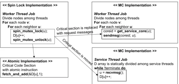
5.4.1 Pseudo code of triangle counting implementation using Spin, Atomic and MC. . 35
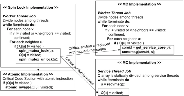
5.4.2 Pseudo code ofBFSimplementation using Spin, Atomic and MC. . . 36
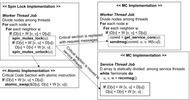
5.4.3 Pseudo code ofSSSPimplementation using Spin, Atomic and MC. . . 38
5.4.4 Pseudo code for fine–grained parallelization of convolution layers using the MC model. . . 41
5.4.5 Overview of the convolutional layer in fine–grained parallelization using the MC model. . . 42
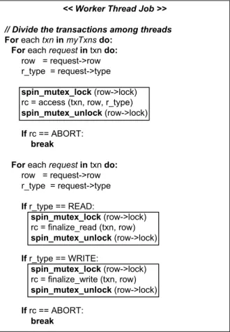
5.4.6 Pseudo code ofYCSBimplementation using shared memory synchronization. . . 43
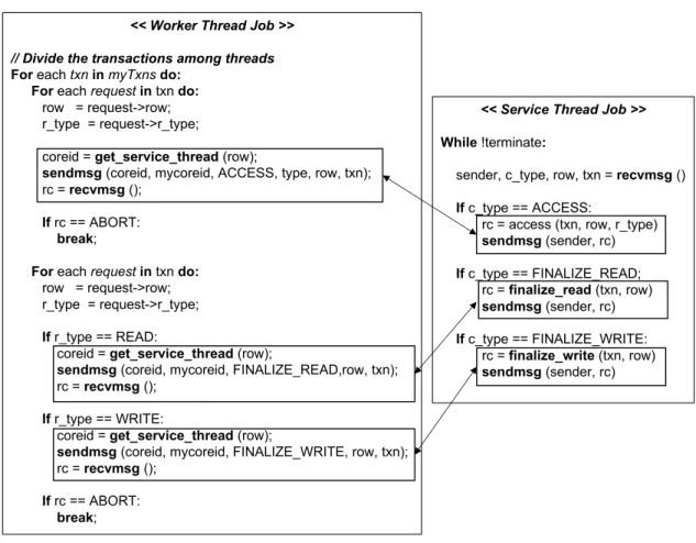
5.4.7 Pseudo code ofYCSBimplementation using the MC model. . . 44
6.2.1 Average per-benchmark performance scaling results using the Spin model. . . 50
6.2.2 Completion time results under Spin, Atomic and MC models. All results are normalized to Spin. . . 51
6.2.3 Contention vs. performance of MC and Atomic models forSSSP,TC, andBFS. . . 52
6.2.4 Contention vs. performance of MC and Spin models forYCSBworkload. . . 53
6.2.5 Normalized performance of MC models with and without reply messages against the Atomic model. . . 55
6.2.7 Performance ofSSSPunder MC model with and without test before sending critical
section invocations. . . 57 6.2.8 Correlation of service core count with shared work. . . 58 6.2.9 Average performance scaling results of MC compared to Spin and Atomic models. 60 6.2.10 Average per-benchmark performance scaling results of MC over the Atomic model. 60 6.2.11 Load imbalance of Atomic and MC models at various core counts; normalized to
respective 8 cores results. . . 61 7.2.1 Average speedup of spatial MC over Spin and Atomic models as the core counts
increase. . . 69 7.2.2 Completion time results for Spin, Atomic, and MC at 512 cores; all normalized to
Spin. . . 70 7.2.3 Performance comparison of MC-reply with default MC and Atomic at 512 cores;
all normalized to Atomic. . . 72 7.2.4 Performance comparison ofSSSPunder MC with and without test before critical
section request at 512 cores; all normalized to MC. . . 74 7.2.5 Dynamic energy results for Spin, Atomic, and MC at 512 cores; all normalized to
Spin. . . 75 7.2.6 Core scaling results for Spin, Atomic, and MC implementations ofPAGERANK,
CCandCOMM. . . 77
7.2.7 Core scaling results for Spin, Atomic, and MC implementations ofSSSP,TCand
BFS. . . 78
7.2.8 Core scaling results for Spin, Atomic, and MC implementations ofALEXNET and SQUEEZENET. . . 79 7.2.9 Correlation of service core count with shared work for SSSP, TC and BFS at
different core counts. . . 81 7.2.10 Normalized core scaling results of MC, and MC tmp; all normalized to MC at 64
cores. . . 82 7.2.11 Normalized core scaling results of MC, and MC shmem; all normalized to MC at
List of Tables
Page
6.1.1 Input graphs and their respective statistics. . . 49 7.1.1 Architectural parameters for evaluation. . . 64 7.1.2 Problem sizes for parallel benchmarks. . . 67
Chapter 1
Introduction
With the proliferation of shared memory processors with hundreds of cores on chip [1] [2], both fine and coarse–grain thread synchronization has emerged as a significant challenge for performance scaling. Conventionally, thread synchronization is realized using standalone atomic instructions, or using synchronization primitives such as spin–based locks [3] [4] [5] [6] [7]. At small core counts, spin-based synchronization primitives are efficient. However, the overheads of such primitives exponentially aggravate as the core count increases [8] [9]. This primarily happens due to expensive cache line ping–pong between cores as a result of the increased latency of the on-chip network. It also incurs instruction retry overhead that results in higher dynamic energy consumption. Perfor-mance scaling can be improved using atomic instructions (when applicable) since they eliminate the overheads of lock acquisition, such as instruction retries and lock variable ping-pong. However, the shared data still ping–pongs between cores, and the expensive coherence traffic leads to performance scaling challenges at higher core counts. Moreover, the type of atomic operations are limited, hence they may not be generalized for arbitrary critical code sections. Therefore, this thesis proposes to utilize a novel moving computation to data (MC) model to overcome the synchronization challenges
for futuristic 1000–cores scale multicores.
The key idea is to keep shared memory cache coherence and accelerate thread synchronization using the MC model. In the MC model, shared data is logically pinned to a dedicated thread, called
service thread. Theworker threadsexecute application code and invoke requests to update shared
data at theservice thread. By utilizing the MC model, any type of synchronization can be realized without ping–ponging of shared data, as it is pinned to a dedicated thread. For example, the critical sections can be offloaded to the service thread to accelerate fine–grained synchronization, and barrier type of coarse–grained synchronizations can be implemented in a more efficient way. The MC model can be implemented by utilizing shared memory cache coherence in which a software based shared buffer is deployed to communicate messages between workers and the service thread. RCL [10] proposes a similar approach to improve performance of POSIX locks using remote core locking. Unfortunately, the shared buffer ping-pongs between the worker and service threads, leading to the same synchronization challenges at higher core counts. Therefore, in this thesis,the
communication between worker and service threads is carried out using auxiliary send and receive instructions implemented at the hardware-level using a low-latency point–to–point messaging network. Note that all on-chip and off-chip data accesses are still managed using shared memory load and store instructions using the hardware cache coherence protocol.
The MC model pins shared data at theservice thread, and thus enhances shared data locality. Moreover, by utilizing hardware based explicit messaging to enable non–blocking communication,
theworker threadsoverlap the critical code section executions with other useful work. In addition,
as compared to the lock based critical sections, it gets rid of the lock acquisition overheads, such as instruction retries and the mutex variable ping–ponging, by completely eliminating the locks. Utilizing a singleservice threadmay become performance bottleneck due to serialization of multiple requests. Therefore, to exploit concurrency in critical section execution requests, multiple service cores are assigned asservice threadsand the shared data is divided among them. The remaining
worker threads exploit concurrency in the underlying algorithmic code, and direct the requests to the corresponding service threads. This thesis proposes to utilize distribution of theworkerand
service threadsamong dedicated cores in a spatial setting.
The key challenge of the spatial MC model is the need to load balance the work between cores executing the worker and service threads to obtain near-optimal performance scaling. One idea is to temporally map aworkerand aservice threadin each core, similar to Active Messages [11]. This achieves load balance, but at the cost of doubling the number of threads relative to the core count. More threads now participate in synchronization, and thus potentially increase the overall communication stalls on chip. The temporal MC model outperforms the spatial model at lower core counts, however as the number of cores approaches hundreds to a thousand cores on chip, the spatial MC model is expected to better utilize the on-chip network resources. However, load balancing the worker and service core counts can be challenging as it is workload dependent. Therefore, this thesis explores a novel heuristic to determine load balanced mapping of the worker and service threads for the spatial MC model. The heuristic relies on the percentage of shared work in an application to decide the number of service cores. If selected properly, the service cores match the concurrency needs of shared work, while the worker cores optimally exploit concurrency in the remaining algorithmic work for a given workload.
The contributions of this thesis are as follows:
1. A spatial moving compute to data (MC) model is proposed utilizing low–latency hard-ware explicit messages to accelerate synchronization. The MC model mitigates cache line ping–pong, improves data locality, and hides communication latency with non–blocking messaging [12] [13]. These key aspects deliver high performance scaling for both fine and coarse grain synchronization in parallelized workloads from the machine learning, graph processing and database domains. Moreover, a heuristic based on profiling the percentage of
shared work is introduced for efficient spatial distribution of worker and service cores in the MC model.
2. The MC model is prototyped and evaluated extensively onTileraR Tile-Gx72TM
multicore machine [14] as it has the largest core count among commercially available processors with in–hardware explicit messaging. A scaling study up to 64 cores is conducted, and enhanced performance benefits of the MC model over the traditional shared memory synchronization are shown as the core count increases.
3. Since Tilera machine contains only 72 cores, to explore 1000-cores scale multicore system, a RISC-V based multicore simulation environment is built and utilized to characterize the spatial MC model, and compare performance and energy consumption over both spin-lock and atomic instruction based synchronization models [15]. In addition, the spatial MC model is also evaluated against the temporal MC model. Furthermore, a software shared buffer based moving compute to data model is implemented, and the MC model with in–hardware explicit messaging is evaluated against it. The spatial MC model with hardware support is shown to enable superior performance scaling up to 1024 cores.
The rest of the thesis is organized as follows. Chapter 2 talks about the related work. Thread synchronization in traditional shared memory paradigm and the proposed MC model are discussed in Chapter 3. Architectural extensions required to enable efficient implementation of the MC model is described in Chapter 4. Chapter 5 discusses the programming model and how a given shared memory based workload is implemented using the MC model. The evaluation of the MC model on
TileraR Tile-Gx72TMmulticore platform is discussed in Chapter 6. The evaluation of the MC model
on 1000-cores scale multicore simulator is presented in Chapter 7. Finally, Chapter 8 concludes the thesis.
Chapter 2
Related Work
Parallel architectures that combine shared memory paradigm and explicit messaging have been ex-plored by researchers. Alewife and ActiveMsg [16,17] have integrated the idea of message passing into shared memory multiprocessors to mitigate the bottleneck of inter-processor communication. More recently, Tesseract [18] utilizes message passing only architecture, and demonstrates the benefits of such communication style. It utilizes a near memory approach in which a high number of simple cores are located closer to a 3D stacked memory. However, as it does not support shared memory paradigm, it differs from the investigated architecture. ADM [19] supports both shared memory coherence and hardware messaging, and tries to accelerate task scheduling by employing the core–to–core messaging. However, it falls short on exploring it for general purpose synchronization.
The commercial Tilera [20] architecture implemented a multicore processor which supports both cache coherence and hardware messaging using a User Define Network (UDN). However, its messaging capability is not fully explored with novel communication models. Barrier synchroniza-tion is investigated using the low–latency hardware messaging by TSHMEM [21] work. However,
it does not these capabilities for real parallel workloads to accelerate synchronization. Moreover, Tilera falls short to analyze the benefits of explicit messaging based communication model at higher core counts.
The idea of MC style critical section execution is investigated in RCL [10]. It utilizes a software only approach without any hardware support. The critical section requests are placed into a shared buffer, then server thread executes them as remote procedure calls. They only target 48 cores system and the investigated applications contain only single lock. As it utilizes a shared buffer for the critical section requests, it is expected to limit the performance at higher core counts. It is also not clear how the proposed model would work for the applications with fine–grained critical sections. In this thesis, a similar implementation of MC termed as MC shmem is presented to illustrate the shortcomings of such approaches and the default MC model is evaluated against it.
Similar to RCL, ACS [22] explores the critical section migration, however, with hardware support. Similar to proposed MC model, ACS also ships the critical section block to a dedicated core. However, its target architecture is a small-scale heterogeneous multicore, where it contains several small cores and a large core. It ships the critical section execution to the large core. On the other hand, the proposed MC model is implemented targeting symmetric multicores at 1000– cores scale. In both approaches, the serialization of the critical section plays a significant role in performance. ACS tries to solve the serialization problem at the dedicated core by utilizing two approaches. The first one is to use simultaneous multithreading to enable multiple threads to execute critical sections concurrently. The second method is to utilize a serialization detection scheme to determine whether or not to offload the critical section execution to the large core. This work addresses the serialization problem by assigning multiple cores to concurrently perform the execution of critical code sections. For this purpose a profiling based heuristic method is proposed to determine the number of service cores that are dedicated for managing work on shared data. Moreover, I utilize emerging workload domains from graphs, and machine learning to evaluate the
proposed spatial MC model.
Active Messages (AM) [11] also explores the usage of hardware message passing on top of a shared memory architecture. However, it only explores a model similar to the temporal MC model in which a separate hardware context is used as a message handler. This work investigates both spatial and temporal approaches and shows better scaling with the spatial MC model as compared to temporal. In addition, AM has not been evaluated against efficient atomic instruction based synchronization in real workloads.
HAQu [23] and CAF [24] demonstrate that fine–grain synchronization can be accelerated in multicores using hardware queues. HAQu accelerates queues in the program’s address space with the extension of new instructions. On the other hand, CAF utilizes new hardware extensions to the on-chip network to mitigate queuing bottlenecks. Both approaches investigate similar models to the proposed MC model using the architectural extensions. However, the application domains differ between their work and the model presented in this thesis. Moreover, this thesis studies the benefits of the MC model on 1000-cores scale multicores, and compares to both spin-based shared memory synchronization as well as efficient atomic instruction based synchronization.
Chapter 3
Thread Synchronization Models
This chapter first outlines the traditional cache coherence based thread synchronization, and dis-cusses its shortcomings. The MC model is then explained to solve the challenges of the traditional synchronization primitives. The chapter concludes with a discussion on the challenges of the MC model, and the proposed solutions.
3.1
Shared Memory Synchronization
Shared memory cache coherence provides ease of programming, flexibility on sharing data between threads, and seamless data movement. However, thread synchronization under shared memory cache coherence at higher core counts becomes a significant performance bottleneck. This is mainly due to expensive ping–ponging of shared data between private caches of the participating cores. Traditionally, spin based synchronization primitives such as locks are realized using atomic instructions (e.g., load–link and store–conditional instructions) to update shared data in a thread safe fashion. However, in order to realize such synchronization, a separate lock variable needs to
be acquired before getting into critical code section, which incurs additional overheads. At lower core counts, and under low contention, these primitives are efficient as they enable concurrent execution of the critical sections. However, when there is contention on shared data, the threads can often fail to acquire the lock, therefore they spin over the shared lock variable until it is available. This process easily boosts the locking overheads due to instruction retries and ping–ponging of the lock between cores. In addition, as the number of cores in the system increases, the cost of lock acquisition drastically goes up due to increased network latency.
The locking overheads can be eliminated by directly utilizing atomic instructions. Instead of acquiring a lock variable to protect a critical code region, standalone atomic instructions are employed. These instructions are implemented using the hardware coherence protocol where each atomic instruction performs an exclusive read to lock the cache line in the level-1 cache, performs the operation, and stores the result before unlocking the cache line. If another core wants to perform an atomic operation on the same cache line, it needs to acquire exclusive copy to perform the operation atomically. However, the shared cache lines still bounce between cores when multiple threads access them temporally. Therefore, as the number of cores increases (1000–cores scale), the bouncing affect leads to degradation on performance scaling due to elevated network latency. Another key limitation of atomic instruction based synchronization is the limited number of operations in the ISA for implementing a diverse set of critical code sections. As a result, as opposed to spin lock based synchronization, they are not applicable to any arbitrary critical section.
In this work, for more efficient and generic thread synchronization, the MC model is proposed and evaluated against both spin-based (Spin) and atomic instruction (Atomic) based synchronization. The MC model and the architectural extensions for efficient implementation of it are discussed in detail in the subsequent sections.
<< Spin Lock Implementation >> Worker Thread Job
spin_mutex_lock(lock); Critical Code Section
tmc_spin_mutex_unlock(lock);
<< Atomic Implementation >>
atomic_fetch_add, compare_and_swap etc.
<< MC Implementation >> Worker Thread Job
ServiceCore = get_service_core(lock) send_x(ServiceCore, data_1,...,data_x)
<< MC Implementation >> Service Thread Job
data_1, …, data_x = receive() Execute Critical Code Section
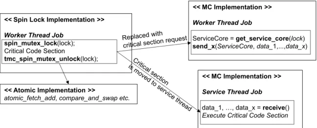
Figure 3.1.1: Implementation of fine-grain synchronization using spin-lock, atomic, and MC models.
3.2
Moving Compute to Data Model
Moving computation towards data technique has gained tremendous popularity in recent years due to explosion of computing on massive datasets [25]. Traditionally, distributed computing domain has deployed computation migration to mitigate performance and energy bottlenecks of moving large amount of data between server nodes. In this model, a data segment is pinned to a node, and the executable is moved towards it. As the executable is significantly smaller than the data, moving overhead is also notably smaller. In a single chip multicore processor, I propose to utilize this approach to mitigate the bottleneck of shared memory thread synchronization, as the core count approaches the 1000-cores scale.
In the proposed MC model, the protected shared data is mapped to a dedicated core and updated only at that specific core by moving computation towards it using explicit messages. In the context of fine–grained synchronization, as demonstrated in Figure3.1.1, the locks and atomic instructions in a traditional shared memory application (the pseudo code in the left two boxes) are eliminated, and the critical code sections are moved to the dedicated core, termed asservice thread
<< Atomic Implementation >> atomic_fetch_add(&barrier, 1); << Spin Lock Implementation >>
spin_mutex_lock(lock); barrier = barrier + 1; spin_mutex_unlock(lock); Ifbarrier == num_of_cores: passed = True; Else:
While passed != True { }
<< MC Barrier Implementation >> Barrier Thread
For each core:
receive();
Foreach core:
send_1(core, continue);
<< MC Barrier Implementation >> Worker Thread
send_1(BarrierCore, barrier);
receive();
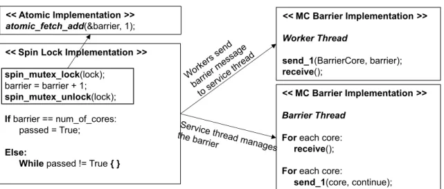
Figure 3.1.2: Implementation of barrier synchronization using spin-lock, atomic, and MC models.
(the pseudo code in the upper right box). Theworkersexecute the application work, and when they need to execute the critical section, they send explicit request messages to invoke fine–grain synchronization at theservice thread. Deploying only a single core asservice threadmay result in higher serialization overhead, hence multiple cores are assigned as service thread to exploit concurrency across independent critical code sections. In this case, the shared data is distributed among the availableservice threads, and theworkersforward their requests to the corresponding
service threadby utilizing a software lookup function. The amount of data that is sent for the critical
section request depends on the application requirements. While some workloads only require a single word, others need multiple words of data. Theservice thread then receives the required number of words in the order they were sent, and execute the critical code section. An application may or may not require the service thread to send a reply back to the requesting worker. This decision may be needed to ensure data consistency in certain scenarios and may impact performance.
Barrier synchronization is an example of coarse–grained synchronization in which blocking communication is required. Instead of loading and updating the barrier variable atomically by each core as illustrated in Figure3.1.2(the pseudo code in the left boxes), the cores send “barrier”
messages to a predefined service thread (the pseudo code in the right box). After sending the “barrier” message they wait for an explicit reply from theservice threadthat manages the barrier. When theservice thread receives all the messages, it replies with a “continue” message to each participating core. This way, instead of spinning over a shared variable, and ping-ponging the cache line between threads, synchronization is done by communicating with aservice threadvia explicit messaging. This work employs one of the workers (Core 0) as theservice threadto manage the barrier synchronization. When the Core 0 completes its worker task, it starts handling the barrier messages.
The proposed MC model can be realized either by employing software shared memory buffer based inter-core messages, or by introducing in–hardware explicit messaging. Even though the implementation using software messaging is not expected to be efficient, for completeness, the discussion and the evaluation is included as one of the baselines in the work.
3.2.1
Moving Compute to Data Model in Shared Memory (MC shmem)
In this approach, similar to the explicit communication in MPI [26], the messaging between worker and service threads is accomplished using a shared software buffer per service thread. However, as opposed to MPI programming model, MC shmem utilizes shared memory programming model (c.f. Section5.1). MC shmem approach is very similar to RCL [10] work in which the locking is done in remote cores, and the requests are delivered using a shared request buffer per server core. Similarly, in MC shmem, a shared buffer per service thread is utilized for the communication between worker and service threads. Each buffer slot contains a flag and a place holder for the data to be sent. To be able to send a message to a particular service thread, a worker atomically increments the write pointer of the corresponding buffer, then places its data into the slot, and sets the flag. The atomic increment on the pointer makes sure that multiple workers do not write to the
same slot. The service thread starts from beginning of the buffer and checks the flag of each buffer entry one by one and reads the data and performs the critical section. If the service thread reaches to a buffer slot in which the flag is not set yet, it spins over the flag until the data is available. The shared buffer is implemented in a way that it has enough capacity to hold all the requests. It can also be implemented with limited capacity as a ring buffer. However, the experimental results for the workloads of interest suggest that utilizing a regular buffer outperforms the ring buffer. Therefore, in this thesis, a large shared buffer per service thread is utilized.
This implementation of the MC model pins the shared data block in the service threads and benefits from non–blocking communication. However, the shared buffer utilized for explicit communication bounces between worker and service threads. In the case of Spin and Atomic based synchronization, if there is no contention in the shared data, the ping–ponging affect can completely vanish. On the other hand, implementing MC approach in shared memory leads to constant ping–ponging of the shared buffer. The aforementioned non–blocking communication may ease the cost of ping–ponging by allowing worker threads to hide the communication latency. However, at higher core counts, the impact of ping–ponging is expected to limit performance. As a result, in order to enable efficient implementation of the MC model, hardware support for explicit messaging is introduced as an auxiliary mechanism.
3.2.2
In–hardware Core–to–Core Explicit Messaging
As discussed in the previous section, achieving moving compute to data model using solely cache coherence has similar limitations with other shared memory synchronization models. Therefore, architectural support for core–to–core communication is required to efficiently scale to 1000–cores. In this regard, this work introduces auxiliary support for low-latency core–to–core communication. Four explicit messaging instructions are introduced in the ISA, and the required micro–architectural
support is added to each core pipeline (c.f. Section4).
1. Sendinstruction does not block the pipeline. It requires the destination core’s address along with the data to be sent from the sender’s register file to the receiver’s register file.
2. Recvinstruction stalls the pipeline if the data is not present at the receive queue of the core that issued this instruction. Once the data arrives, therecvinstruction pulls the data from the receive queue and places it into the register file.
3. Sendr(send with rendezvous) instruction is a blocking send instruction in which an explicit reply is expected from the destination core.
4. Resumer(resume rendezvous) instruction is a non-blocking special send instruction which is used to reply to thesendrmessages.
The details of the explicit messaging protocol and the architectural extensions are discussed in Section4. By utilizing these low–latency messaging instructions, worker and service cores exchange messages between their register files without involvement of the cache coherence. In the case of fine–grained synchronization where non–blocking communication can be used, the worker threads make use of thesendinstruction to request critical section executions, and it is paired withrecv
instruction on the service thread side. If a blocking communication is needed, thensendr/resumer
instructions are utilized. Thus, the cache line ping–ponging never happens when exchanging messages between cores.
Once the messaging is implemented with hardware support, the MC model provides two key advantages. First, it prevents unnecessary ping–pong of shared data by pinning it to service threads. However, for certain applications, shared data can be read by other threads to enable work efficient execution of the algorithm. The second advantage is that if non–blocking communication is utilized in the worker side, the MC model enables to efficiently overlap communication overheads
with computation. With this approach, worker and service tasks are pipelined, and additional communication stalls are hidden. In addition, the workers can have multiple back to back in– flight request messages, and possibly further ease the overheads of worker to service thread communication. The shared memory based models, on the other hand, suffer from cache line ping-pong and blocking communication stalls. The benefits of MC with in–hardware explicit messaging are expected to be more notable at higher core counts as the distance between sharer cores and the network congestion increases.
3.2.3
Worker and Service Thread Distribution
The main challenge with the MC model is the determination of the right number of worker and service threads in the spatial setting to exploit application parallelism in a load–balanced way. This approach requires tuning the ratio of worker and service threads to achieve near-optimal performance, otherwise the system suffers from the work imbalance. The other approach is to utilize two context per core and temporally employ the same core for both worker and service threads. In the following two subsections, both distribution approaches are discussed in more detail.
Spatial Moving Compute to Data Model
In this distribution approach,worker and service threads are spatially assigned to the available cores as shown in Figure3.2.1. A naive way to achieve the right thread mapping is to perform an exhaustive search by varying the number ofworker and service threads, and determine the best performing mapping. This approach may be used at low core counts, however it gets time consuming as the number of cores increases. In addition, each workload is expected to require different ratio due to its unique data structure and synchronization requirements. To overcome these challenges, this work proposes to deploy a profiling based heuristic. The heuristic relies on the
...
...
...
...
...
...
...
...
...
...
...
...
...
...
...
...
...
Figure 3.2.1: Spatial distribution of worker and service threads.
correlation of the number ofservice threadsand the percentage of shared work in a given workload. In this method, the shared memory version of the application is profiled to obtain the average time spent in critical code sections (shared work) compared to the total completion time. If the time spent in critical code sections is high, the requiredservice thread count is also high, and vice versa. If the shared work percentage results in less than1service threaddue to very small shared work, it is assigned a single service thread. Moreover, at most half of the cores are assigned to theservice
threadtask because the work being done by each worker thread increases as the number of workers
decreases.
Temporal Moving Compute to Data Model
To support the temporal MC model, each core needs to be extended with two register files, an explicit messaging–aware switching policy logic, and selection logic for register reads/writes to support hardware multi–threading. Each hardware context in a core is then mapped to a single
service threadand a singleworker threadfor temporal mapping. Hence, the number of worker and
service threads is always equal to the number of used cores. This approach eliminates the need to tune the number ofworkerandservice threads. However, it requires an additional context and
special switching policy that takes explicit messaging into account for fast context switching. In addition, the number of threads participating in the synchronization becomes 2 times the number of cores which may incur additional communication stalls at higher core counts. Consequently, the spatial model is preferred at higher core counts, since (1) the available cores are relatively easier to load balance, and (2) the number of threads participating in synchronization must be kept in check to minimize unnecessary communication stalls.
Chapter 4
Architectural Extensions for Efficient
Implementation of the MC Model
As discussed in the previous chapter, in–hardware explicit messaging is required for efficient implementation of the proposed moving computation to data model. Hence, this section is dedicated to discuss the baseline multicore architecture, and the hardware extensions to enable fast core–to– core direct communication for the MC model. Furthermore, detailed description of the explicit communication protocol is also provided. The discussed architecture and the messaging protocol is modeled in a simulator environment to evaluate MC model at 1000–cores scale. In addition, the proposed model is also prototyped on Tilera Tile-Gx72 multicore system as it offers hardware support for direct core–to–core messaging on top of shared memory cache coherence. Therefore, the chapter is concluded with a section on the architectural details of the Tile-Gx72 machine.
Multicore L1-D L1-I S T B L2 Directory Mem. Controller Compute Pipeline S Q R Q Router Router F D E M W L1-D L1-I STB L2 Directory Router Router R Q MU Register File send send recv recv recv
send_1(coreid, data_1) …
send_n(coreid, data_1, data_2, …, data_n)
sender_core = receive_1(&data1) …
sender_core =receive_n(&data_1, &data_2, … &data_n)
Figure 4.1.1: Overview of a tile and architectural extensions.
4.1
Architectural Overview
The baseline is a tiled multicore architecture. Figure4.1.1shows a logical view of a tile within the proposed multicore processor. The tiles are connected to each other with a 2-D mesh interconnection network. Each tile includes a single issue RISC-V [27] core, private level-1 instruction and data caches, a shared last-level cache with an integrated directory for MESI cache coherence protocol, and a network router for inter-core communication. Memory controllers are attached to some of the tiles to enable off–chip memory accesses. Four explicit messaging instructions are added into the RISC-V ISA, namely,send, recv, sendr, and resumer. The tiles are extended and shaded modules are introduced to support these instructions on top of shared memory. The syntax of the send/receive operations is shown in the figure. When a send instruction is executed, messaging unit (MU) reads the CoreID and the data from the specified registers, and creates a packet to be sent to the on-chip network. The extended on-chip network transmits the message to the receive queue (RQ) at the destination core, and the messages are buffered in the receive queue until the receive instruction is executed. Once the instruction is executed, MU pulls the data from the RQ and places it into the specified registers. The detailed description of the protocol is discussed in Section4.2. Note
that shared memory cache coherence is retained in the system, and the explicit messaging support is added as an auxiliary support to achieve efficient implementation of the proposed MC model. In addition to explicit messaging capability, per-core 4-way SIMD that can operate on four 16-bit floating point numbers are added to have state–of–the–art implementations of machine learning algorithms. Associated instructions, such as fused–multiply–add are also integrated into the ISA. Furthermore, RISC-V ISA’s standard extension for atomic instructions [27] are implemented. These instructions such as load–reserved and store–conditional are employed to implement shared memory synchronization primitives.
In default mode, the cores are single–threaded, and the application threads are spatially dis-tributed among available cores. In addition to spatial mode, multiple threads per core with hardware level context switching is also supported to enable temporal thread distribution of threads as dis-cussed in Section 3.2.3. To support hardware multi–threading, each core is extended with two register files, an explicit messaging–aware switching policy logic, and selection logic for register reads/writes. The switching policy interacts with the receive queue to initiate thread switching when a message arrives. These supports in microarchitecture are utilized to implement the temporal MC model. In the temporal MC model, it is crucial forservice threadto perform its work prudently be-cause otherwise the receive queue may suffer from contention, and possibly also lead to application level deadlock. Therefore, theservice threadsare given a higher priority, and whenever the receive queue receives a message, the policy switches to theservice threadand all messages in the queue are processed.
If ``capacity counter’’ > 0 1. Inject the message
into network 2. Decrement capacity
counter
Sender Router Router QR Receiver
The message traverses the network
If Receive Q has space
Insert the message Receive the messagefrom top of the receive queue 1 Construct the message 2 3 4 5
ACK message is sent
when the message is deallocated from the receive queue
6 ACK message
traverses the network 7
Capacity counter is incremented when the ACK message is received
8
Figure 4.2.1: Explicit messaging protocol.
4.2
Explicit Messaging Protocol
As discussed in Section3.2, the MC model utilizes both blocking and non–blocking communication to accelerate fine and coarse–grained synchronization. The introduced explicit messaging support provides capability to realize both types of communication between worker and service threads.
4.2.1
Non–blocking Communication
This communication type is utilized to implement the MC model to achieve fine–grained non– blocking synchronization. Asendinstruction at the worker core is paired with a correspondingrecv
instruction at the service core to implement non–blocking core–to–core communication. Asend
instruction does not block the pipeline if the messaging network is available to inject the message. This allows the worker core to continue with other useful work while the message traverses the network to its destination. Moreover, the worker can have multiple in–flight messages as long as the network flow–control permits. This type of communication helps overlap communication latency with other computations.
Figure4.2.1illustrates the protocol implementation for core–to–core non–blocking communi-cation. First, the destination address is calculated using the receiverCoreID, and placed into an architected register. Then, a message is constructed by the sender core’s pipeline by executingsend
instruction with the address and the data (1). The constructed message consists of a header contain-ing the destination address and the message size, and the payload. Each send instruction supports up to 4 words. The message can contain a pointer to a function along with the necessary data to be executed, or just arbitrary data that the destination core needs to perform some computation. The programmer needs to make sure that the receiver side knows what type of message, and how many words are being sent to it. The protocol utilizes a special per–core counter called“capacity counter”
(2), and an implicitACKmessage (6) to enable flow–control for messaging. Thecapacity counter
tracks the number of in–flight messages, and the senders cannot have more in–flight messages than the setcapacity countervalue. This counter is essential for supporting thread migration and virtualization in the proposed architecture. The programmer sets this counter by setting a special register at the beginning of the program execution. When a message is inserted into the network, the corresponding core decrements its capacity counter. When the counter value reaches to0, the
send instruction is stalled in the pipeline. When the message is injected into the network, it is routed to the destination core using the on-chip network (3). For this protocol to work correctly, it is assumed that the messages from a same source to a same destination are ordered in the network. In addition, the routing algorithm is assumed to be deadlock–free. Once a message arrives at the destination’s receive queue (4), it is pulled by the destination core’srecvinstruction (5). Therecv
instruction always blocks the pipeline. If the core executes therecvinstruction before the message arrival, it stalls until the data arrives at the receive queue. The programmer is responsible for adding subsequent code to decode the received message, and initiate execution of the appropriate code region using the received data. After each message is read from the receive queue, an implicitACK
message is generated to traverse back to the source core (6&7). ThesendandACKmessages use separate networks (in addition to the ones used for cache coherence) to avoid deadlock, as utilizing the same network for both type of messages may lead to circular dependencies in the network. The
stalled) is allowed to proceed.
4.2.2
Blocking Communication
In several application scenarios, a strong consistency is required or a piece of data is needed from the destination core. In this case, the sender waits for an explicit reply from the receiver. It can be implemented by executing arecvinstruction followed by asendinstruction in the sender core, and a sendinstruction followed by the recv instruction in the receiver core. Unfortunately, the
send – recvinstruction pairs may result in a deadlock if the receive queue has finite size, and both
communicating cores use the same network to send their messages. For example, consider a master core that dispatches work to the worker cores. All the workers send work request messages to the master, and then wait for their explicit reply by executing a recvinstruction. If the number of messages sent are more than the receive queue size of the master core, the messages block the network responsible for the send traffic. When the master tries to inject a send message to the router for replying to one of the workers, it cannot proceed because the send network is filled with the overflown messages. Moreover, the master core cannot pull any more data from the receive queue because it is stuck at executing the send instruction. Hence, the deadlock situation occurs. Therefore, for the blocking communication, specialsendrandresumerinstructions are implemented. In this case, the explicit reply messages are always sent using aresumerinstruction which flows on the dedicated reply network withACK messages.
Unlikesendinstruction, thesendrblocks the pipeline until theresumerreply message is received at the sender core. At the receiver core, therecvinstruction is utilized to receive thesendrmessage. However, the sender address is stored to be utilized by theresumerinstruction. This explicitresumer
reply message is routed back to the sender core. This message is directly delivered to the pipeline without getting into the receive queue. Upon receiving the message thesendrinstruction completes.
The implementation of the MC based barrier as described in Section 3.2 is realized employing these two instructions. The workers participating in the barrier utilizesendrinstruction for barrier message to the master core. The master core receives all the messages withrecvinstruction, and resumes the participating cores withresumerinstruction.
4.2.3
Deadlock Freedom
Application Level Requirements
To avoid application level deadlock, the proposed architecture allows messages from different sender cores to arrive inany orderat the destination core. Ordered message arrival can only be enforced if the architecture enables receive queues for each sender core, which is an unnecessary burden on the hardware. To keep the overhead of receive queue per core low, the unordered message arrival must be handled in the application software. The programmer must decode each received message, and invoke the appropriate software routine(s) to handle the request from the corresponding sender core.
Protocol Level Deadlock Freedom
Limited buffering in receive queues can lead to protocol level deadlocks. In the proposed protocol that does not impose ordering of message arrivals, the application software ensures forward progress. However, if threads impose order of arrival restriction, the finite size of receive queues can lead to protocol level deadlock. This scenario can be resolved by always replying to the sender either explicitly (throughresumer) or implicitly (through anACKmessage). This reply message in turn increments thecapacity counterat the sender, which is used to avoid overflowing the finite sized receive queues.
Network Level Deadlock Freedom
It is assumed that the network guarantees the message arrival orders from the same source to the same destination. In addition, the routing algorithm is assumed to be deadlock–free, or it is assumed to have a deadlock recovery mechanism. Even with these assumptions, the system can deadlock if the same network is deployed for both request messages and the reply messages. For example, if theACK message uses the same network with thesendmessage, it can cause circular dependency between threads, and lead to deadlock. Hence, a dedicated network is utilized forACKandresumer
messages to separate them fromsendandsendrmessages to remove possible deadlock scenario.
4.2.4
Message Consistency
Certain application communication patterns may require message consistency, i.e., a sender thread must ensure the delivery of prior messages to their destination before commencing with other work. The ISA is extended with a “message fence” instruction, which ensures that all pending messages are pushed into the network and observed at the receiving side. This is ensured by monitoring the
capacity counter since it tracks all in–flight messages whoseACKshave not been observed yet.
Once thecapacity counterreaches its initialized value, all sent messages have been observed at their respective destination. At this point the message fence instruction commits.
4.2.5
Thread Migration and Multiprocessing Support
Supporting thread migration is a necessity for a general purpose processor. However, the proposed architecture can deadlock if in–flight explicit messages are not dealt with properly. This can happen because an in–flight message can be delivered to a core where the thread is not running any more. To properly handle this situation, a clean–up mechanism is required to ensure all in–flight messages are
delivered before thread migration can occur. The clean–up mechanism works as follows. The OS halts all the cores from injecting any more messages into the network. After that, the OS monitors
thecapacity counterof each core and waits for them to get back to their initialized values. This
signifies that all the cores have receivedACKsfor all their in–flight messages and there is no explicit message in the network. At this point, the OS can perform the thread migration. It also updates the thread–to–core mapping so that future messages can get to their destination properly. Hardware virtualization support can also be added based on this mechanism.
4.3
Explicit Messaging Hardware Overhead
The architecture requires a receive queue per core to support the proposed protocol as shown in Figure4.1.1. The design space study is presented in [12] to empirically determine the per core receive queue size using the MC model. In this study, the service thread count is set to the best performing service core count for the workloads that require fine–grained synchronization. Then, the per thread sender capacity counter is swept from 2 – 8 with an increment of 2. For each sender capacity counter setting, the maximum utilization among the receive queues, as well as the corresponding performance speedup is measured. It is shown in the paper that beyond a sender capacity of 4, the performance does not improve and results in an increase in the receive queue size. However, from sender capacity of 2 to 4, the performance speedup is considerable while the receive queue size only increases slightly. Therefore, in this thesis, the per thread sender capacity is set to 4. Using this capacity counter value, a study is conducted to determine the required receive queue size. The workloads of interest in this work are run to completion, and their respective maximum receive queue utilization is obtained. Then, the required receive queue size is determined by choosing the largest receive queue utilization among all the workloads. Finally,2.4KBis determined to be the
receive queue size per core in this thesis. In addition to the receive queues, cache coherence and explicit messaging traffic is separated from each other using independent on-chip networks to avoid deadlock.
4.4
Prototyping Explicit Messaging and Cache Coherence on
TILE-Gx72 Machine
TileraR’s Tile-Gx72TMprocessor is one of the few commercially available machines that enable
similar capabilities to the proposed explicit messaging protocol on top of hardware cache coherence. It is a tiled multicore architecture with 72 tiles interconnected with 2-D mesh networks-on-chip, called iMesh Interconnect. Each tile consists of a 64-bit VLIW core, 32 KB private level-1 data and instruction caches, and a 256 KB shared level-2 (L2) cache. A directory is integrated into the L2 cache slices to support a directory–based cache coherence protocol.Tile-Gx72TMarchitecture also offers various configurations for data placement and caching schemes. By default, a cache line is homed at an L2 cache using a hardware hashing scheme, and also replicated in the L2 slice of the requesting core. Experiments with and without replicating cache lines in the local L2 slice of the requesting core varied performance by an average of 1%. Hence, in the rest of the thesis the default L2 homing scheme is utilized. In addition, networks-on-chip are included in each tile to communicate with other tiles, I/Os and the on-chip memory controllers. There are two groups of networks in the system. One is a set of “Memory Networks”, which are utilized for memory and coherence traffic. The other one is a set of “Messaging Networks”, which are deployed to explicitly send messages between tiles (User Dynamic Network (UDN)) and the I/O (I/O Dynamic Network (IDN)) devices. While User Dynamic Network (UDN) is used to enable tile–to–tile direct messaging, I/O Dynamic Network (IDN) is used to send messages to the I/O. UDN is leveraged for moving compute to data model in this work.
Each tile contains four UDN queues for explicit messaging. These queues are implemented as small FIFO queues. Each queue is mapped to a special purpose register, which is used to send and receive data between execution units without any involvement of the cache coherence protocol and traffic. For example:
move udn0, r0 is a send operation in which data inr0is moved to special purpose register
udn0. Then, it is injected into the network where it traverses to the destination tile.
move r0, udn0is a receive operation in which the sent data is received and placed in one of the queues, and since the queues are mapped to special UDN registers, the data is read from the corresponding register (udn0in this case) when it arrives in the specified queue. If the message does not make it to the queue when the “move” instruction is executed, this operation stalls the core pipeline.
Tile-Gx72TMsupports Tilera Multicore Components (TMC) library [28] to initialize and make
use of the UDNs. Hence, low level instructions are not used for explicit communication. For this work, the library calls provided by TMC library for tile–to–tile messaging are used (c.f. Section5.2). To be able to make use of the UDN networks, threads are pinned to cores based on their thread IDs in an ascending order. InTile-Gx72TM, the threads are spatially distributed among available cores.
UDNs inTile-Gx72TM supports both blocking and non–blocking communications using the
library calls for send/receive operations. However, since it does not utilize separate instructions for the reply messages of the blocking communication, it may result in deadlock situation as discussed in Section4.2. However, the blocking communication is used to implement barrier synchronization and the database workload in this thesis, and the offered explicit messaging support is sufficient to realize both database workload and the barrier without deadlocking the system.
Chapter 5
Programming with Moving Compute to
Data Model
The proposed moving compute to data model and the architectural extensions for efficient im-plementation of it are discussed in the previous chapters. Since the proposed approach utilizes a different model to accelerate synchronization, it is also significant to discuss how a given application is programmed with the MC model. Therefore, this chapter is dedicated to discuss programming model, the synchronization primitives and the messaging API inTile-Gx72TMand Simulator, and
the illustration of how a shared memory application is seamlessly translated to the proposed MC model.
5.1
Programming Model
The proposed MC model utilizes shared memory parallel programming model. Threads are created within a process using the Pthreads library [29], and all threads are allowed access to shared data structures. Even though Pthreads is utilized in this work, OpenMP [30] programming model can
Master Worker Thread Worker Thread 1 Worker Thread n pthread_create() Service Thread 1 do_worker_task () do_service_task () Service Thread m
…
…
do_worker_task () do_service_task ()…
…
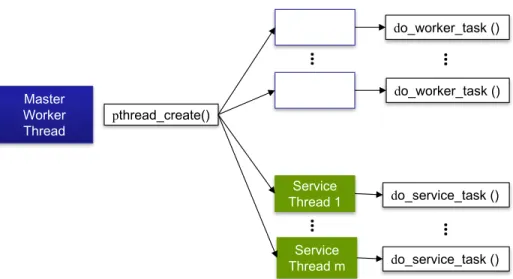
Figure 5.1.1: Thread management with the MC model.
easily be adapted as well. The only difference from traditional thread creation is that two sets of threads are created as shown in Figure5.1.1, and distributed by either jumping to worker routine or service routine. Then, the programming model replaces traditional thread synchronization with the explicit messaging based MC protocol. The service threads perform critical section execution with the request of the worker threads, as discussed in Section3.2. The process of transforming an application to the MC model can be automated by detecting thread synchronization points in the code. The identified critical sections can be moved to a separate procedure, then service threads are to be assigned to these procedures. As similar to RCL [10], Coccinelle [31] or similar refactoring tools can be easily utilized to transform existing applications. However, this work does not utilize any tool to implement the moving computation to data model. Manual transformations of the representative applications are illustrated to show how shared memory synchronization is ported to the MC model.
5.2
Synchronization on
Tile-Gx72
TMTile-Gx72TMplatform provides Tilera Multicore Components (TMC) library to make use of various
synchronization and communication capabilities of the machine. The provided library contains various spin–based synchronization primitives such as simple spin–locks (tmc_spin_mutex_t) and barriers. In addition, it also offers queue based spin–locks (tmc_spin_queued_mutex_t) which provide better fairness as compared to the simple spin–lock. For the workloads presented in this thesis, the performance difference between simple and queue based locks is negligibly small, hence simple locks are utilized. The TMC library also includes atomic memory operations to serial-ize updates on a shared data. In this work,arch_atomic_val_compare_and_exchange()
andarch_atomic_increment()are used to implement critical sections of graph workloads
as discussed in Section5.4.1. Similarly,atomic incrementis also utilized for barrier implementation. The MC model is implemented using the UDN capability of theTile-Gx72TM. The TMC library provides interfaces to enable and utilize the inter–core communication. First of all, the main process that creates the threads executestmc_udn_init()which forms a UDN hardwall with the given
cpu_set_t. Thecpu_set_tspecifies all the CPUs that are granted access to the messaging
network, andtmc_udn_init()routine creates a rectangle that covers all the specified CPUs. After the threads are created, based on the given thread id, the threads are pinned to the cores using
tmc cpus set my cpu()routine. Then, each thread callstmc_udn_activate()to enable
communication using the messaging network within the created UDN hardwall.
Tile-Gx72TMcontains 4 UDN demux queues, hence a message can be sent and received using
any of the queues. The programmer needs to make sure that the queue tag provided while sending the data is matched on the receiver side by calling the proper receive routine. For example, in the MC implementation, demux queue zero is utilized to send/receive the critical section requests. As shown in Algorithm1,tmc_udn_send_n()routine is used to send the request messages to the
Algorithm 1Messaging API between worker and service cores onTile-Gx72TM. 1: <<Worker thread sends x words>>
2: tmc_udn_send_n (header, UDN0_DEMUX_TAG, data_1, data_2, ..., data_n)
3:
4: <<Service thread receives x words>> 5: data_1 = tmc_udn0_receive()
6: data_2 = tmc_udn0_receive()
7: ...
8: data_n = tmc_udn0_receive()
service thread where the message is being placed into the demux 0. It accepts up to 20 words of data, meaning that n can vary from 1 to 20. The send operation requires aheaderwhich is necessary to route the data to the receiver core. Theheaderfor each core is statically created before getting into the parallel region by calling tmc_udn_header_from_cpu(coreid), and placed into an array of headers. Before sending a message, with a simple lookup, the header for the corresponding core is obtained and the message is sent. Similarly, on the service core side, the data is being received from demux 0 by callingtmc_udn0_receive()routine n times.
5.3
Synchronization on Simulator
The simulator supports RISC–V’s standard extension of atomic instructions in addition to load– reserve/store–conditional instructions. The load–reserve/store–conditional instructions are deployed to implement spin–locks as similar to TMC library of Tilera. The barrier synchronization is implemented using both spin–lock and the atomic fetch–and–add instruction,amoadd. For the critical section implementations,amoadd, and amoswapinstructions are utilized. Since RISC– V tool chain supports the GCC builtins for atomic memory operations, in the actual implementation, such builtins are utilized. For example, for atomicfetch–and–add,__sync_fetch_and_add
Algorithm 2Messaging API between worker and service cores using send/receive instructions on
Simulator.
1: <<Worker thread sends x words>>
2: sendmsg_n (coreid, data_1, data_2, ..., data_n)
3:
4: <<Service thread receives x words>>
5: src_core = recvmsg_n (&data_1, &data_2, ..., &data_n)
The MC model is implemented using the send, receive instructions added in the ISA. Similar to Tilera, an API library for messaging is implemented. The syntax of the API is similar to Tile-Gx72TM with some differences. In the simulator, there is only a single receive queue per core, hence there is no need to tag the messages. The data is sent and received as shown in Algorithm2. Instead of a special header, the send operation receives core id as an argument to determine the destination. The receive instruction returns the sender core id in case a reply message needs to be sent. The capacity counter discussed in Section4.2for send operation can be initialized using
set_thread_capacity (). If it is not initialized by the programmer, default value of 1 is
used.
Algorithm 3Messaging API between worker and service cores using sendr/resumer instructions on
Simulator.
1: <<Worker thread sends x words>>
2: return_data = sendr_n (coreid, data_1, data_2, ..., data_n)
3:
4: <<Service thread receives x words and resumes the worker>>
5: src_core = recvmsg_n (&data_1, &data_2, ..., &data_n)
6: resumer (src_core, reply_data)
As discussed in Section4.2.2, in order to implement blocking communication, sendr/resumer instruction pairs are utilized. Various versions of sendr and resumer operations are implemented in the runtime library. An example is illustrated in Algorithm3. In the algorithm, the worker sends
nnumber of words and waits until it receives a single word as a reply. The core id of the sender is stored in line 5, then used in theresumer operation to send explicit reply. There are possible