Middlesex University Research Repository
An open access repository of
Middlesex University research
http://eprints.mdx.ac.uk
Kochekali, Homayun (1991) Force sensing enhancement of robot
system. PhD thesis, Middlesex Polytechnic.
Available from Middlesex University’s Research Repository at
http://eprints.mdx.ac.uk/13488/
Copyright:
Middlesex University Research Repository makes the University’s research available electronically.
Copyright and moral rights to this thesis/research project are retained by the author and/or other copyright owners. The work is supplied on the understanding that any use for
commercial gain is strictly forbidden. A copy may be downloaded for personal,
non-commercial, research or study without prior permission and without charge. Any use of the thesis/research project for private study or research must be properly acknowledged with reference to the work’s full bibliographic details.
This thesis/research project may not be reproduced in any format or medium, or extensive quotations taken from it, or its content changed in any way, without first obtaining permission in writing from the copyright holder(s).
If you believe that any material held in the repository infringes copyright law, please contact the Repository Team at Middlesex University via the following email address:
"
Middlesex
University
London
Middlesex University Research Repository:
an open access repository of
Middlesex University research
http://eprints.mdx.ac.uk
Kochekali, Homayun, 1991.
Force sensing enhancement of robot system.
Available from Middlesex University's Research Repository.
• •
Copyright:
Middlesex University Research Repository makes the University's research available electronically.
Copyright and moral rights to this thesislresearch project are retained by the author and/or other copyright owners. The work is supplied on the understanding that any use for commercial gain is
strictly forbidden. A copy may be downloaded for personal, non-commercial, research or study without prior permission and without charge. Any use of the thesislresearch project for private study or
research must be properly acknowledged with reference to the work's full bibliographic details. This thesis/research project may not be reproduced in any format or medium, or extensive quotations taken from it, or its content changed in any way, without first obtaining permission in writing from the copyright holder(s).
If you believe that any material held in the repository infringes copyright law, please contact the Repository Team at Middlesex University via the following email address:
Force Sensing Enhancement
of
Robot System
by
Homayun KOCHEKALI SSe MSe
A thesis submitted to
the Council for National Academic Awards
in partial fulfilment of the requirements for the degree of Doctor of Philosophy
The work was carried out
at the robotic centre of Middlesex Polytechnic in
collaboration with Welwyn Strain Measurements Ltd. (Basingstoke)
&
Acknowledgement
There are many people to whom I wish to extend my most grateful thanks. To Dr. V.B. Kavina for his role as Director of Studies. His advice has been greatly appreciated.
To my supervisors, Dr. R.A. Whitaker of Middlesex Polytechnic, Professor T.M.
Husband, Vice Chancellor of Salford University, and Dr. K.F. Gill of Leeds University, for their enthusiastic support and kindly guidance.
To my Industrial Collaborators Weiwyn Strain Measurements and in particular to Mr K. Copleston for his practical advice.
To the Polytechn.ic technical staff Mr N. Salam, who helped
in
manufacturingof hardware, and Mr
J.
Morgan for his support and kindly guidance indeveloping the electronic control unit.
To my colleagues at Middlesex Polytechnic, S. Shaheen, C.W. Wong, H. Feelib and in particular Dr. A. Nowrouzi my lifetime friend.
And last, but certainly not least, to my loving family, Ayda my wonderful wife and Manijeh my lovely mother-in-law without whose support I would not have
Abstract
At present there is a general industrial need to improve robot performance. Force feedback, which involves sensing and actuation, is one means of improving the relative position between the workpiece and the end-effector. In this research work various causes of errors and poor robot performance are identified. Several methods of improving the performance of robotic systems are discussed.
As a result of this research, a system was developed which is interposed between the wrist and the gripper of the manipulator. This system integrates a force sensor with a micro-manipulator, via an electronic control unit, with a computer to enhance a robot system. The force sensor, the micro-manipulator and the electronic control unit, were all designed and manufactured at the robotic centre of Middlesex Polytechnic.
The force feedback is provided by means of strain gauges and the associated bridge circuitry. Control algorithms which define the relationship between the force detected and the motion required are implemented in the software. The software is capable of performing two specific tasks in real time, these are:
1- Inserting a peg into a hole
2- Follo~ing an unknown geometric path
A rig was designed and manufactured to enable the robot to follow different geometric shapes and paths in which force control was achieved mainly by control of the micro-manipulator.
Table of Contents
Research Aims . . . .. vii
Research Achievements . . . vii
Presentation of thesis . . . viii
System Operating Principle ... . . . .. x
Chapter 1 ... 1
1.0 Historical Perspective and State of the Art in Robot Force Control. . . . .. 2
1.1 Passive Compliance . . . 3
1.1 . 1 Inh~rent Robot Compliance ... 3
1 .1.2 Additional Compliance ... 4
1.2 Active Compliance . . . 5
1 .2.1 Force Feedback Control . . . .. 5
1.2.1.1 Classical Control 1.2.1.2 Adaptive Control
...
...
6
7 1.3 Special Actuators for Force Feedback Control ... 91.4 Review of Literature Survey ... 13
1.5 Re-Appraisal of Aims . . . 14
Chapter 2 ... 15
2.0 Factors Affecting Robot Performance Accuracy ... 16
2.1 Environmental Factors . . . 16 2.2 Parametric Factors . . . .. 18 2.2.1 Kinematic Parameters ... 18 2.2.2 Dynamic Parameters ... 20 2.3 Measurement Factors . . . .. 23 2.4 Computation Factors . . . 24 2.5 Application Factors . . . 25 Chapter 3 . . . 26
3.0 Methods of Improving Robot Accuracy ... 27
3.1 Calibration Method . . . 28
3.1.1 Robot Calibration . . . .. 28
3.1.2 Workpiece Calibration ... 29
3.1.3 Sensor Frame Calibration . . . .. 29
· 3.2.1 Measurement tasks ... 30
3.2.2 Modelling Tasks ... 30
3.2.3 Compensation Tasks ... 31
3.3 Closed-loop methods ... 31
Chapter 4 ... 33
4.0 The Survey of Force Sensors Mounted on Wrist ... 34
4.1 Separation of Forces and Moments with Strain Gauges . . .. 38
4.2 Design of the Force Sensor . . . .. 41
4.2.1 Manufacture of the Sensing Element . . . .. 49
4.2.1 Sensing Element Material . . . .. 52
4.3 Calibration of Force Sensor ... 52
4.4 Construction of A Geometric Path for the Robot to Follow ... 55
Chapter
5 . . .
585.0 Development of A Micro-Manipulation Device ... 59
5.1 Determination of PUMA 560 Robot Accuracy and Repeatability . . . .. 61
5.2 The Fundamental Design Criteria ... 62
5.3 Design Considerations ... , 63
5.3.1 Central support tube sub-assembly ... 66
5.3.2 Z-Translation Sliding Tube ... 66
5.3.3 V-Translation Sliding Tube ... 67
5.3.4 X-Translation End-effector ... 68
5.3.5 Z-Translation Drive Mechanism ... 68
5.3.6 V-Translation Drive Mechanism ... 70
5.3.7 X-Translation Drive Mechanism ... 70
Chapter 6 ... 71
6.0 Data Acquisition . . . .. 72
6.1 Errors Associated with Digitising a Signal ... 76
Chapter
7 . . .
777.0 Motor Control ... 78
7.1 Methods of Providing Positional Feedback Control . . . .. 78
7.1.1 Pulse Width Modulation . . . .. 78
7.1.1.1 Problems involved with the PWM control system ... 79
7.1.2 Pulse Position Modulation ... 79
7.1 .3 Pulse Code Modulation ... 79
7.1.4 DC control . . . .. 80
7.1.5 Binary Encoding ... 80
7.2 Selection of the control method . . . .. 81
7.3 Implementation of Selected Method . . . .. 82
7.3.1 Summary of Block Diagram . . . .. 82
7.3.2 Role of PC-30A interface card within the control system . . . 82
7.3.3 Detailed Explanation ... 84
7.3.3.1 The need for auto setup . . . .. 96
Chapter
8 . . . 998.0 Software... 100
8.1 Preliminary Program Operations ... 103
8.2 Peg-in-hole Strategy. . . . .. 114
8.2.1 Peg-in-hole Program Operation . . . .. 116
8.2.1 Appreciation of the software . . . .. 120
8.2.2 Example Screen Output. . . . .. 121
8.2.3 Programme 5: Peg-in-hole Insertion Algorithm .... 123
8.3 Path Following Strategy ... 130
8.3.1 Programme 6: Path Following Algorithm . . . .. 133
8.3.2 Example Screen Output . . . .. 136
Chapter
9 . . . 1379.0 Discussions & Conclusions . . . .. 138
9.1 Recommendation for Future Work . . . .. 141
References . . . .. 144
Appendix I Manufacturing of the force sensor . . . ..
153Description of programs for machining the sensing element and overload protection device. . . . 154
eNC programs for machining the sensing element and overload protection device . . . 157
Detail Drawings . . . 160
Material selection and properties data ... 162
Appendix
/ICalibration of the Force Sensor . . . ..
167Tables of data due to loading and unloading of force sensor ... 168 Bar charts to illustrate the effect of strain gauge hysteresis due to loading and
unloading of the force sensor . . . . . . .. 172
Calibration linear graphs where gradients were evaluated from to represent the individual constant 'K' for calibration matrix. . . . 180
Appendix III Design of micro-manipulator . . . .. 186
Accuracy and repeatability data plots of Puma 560 robot using Hewlett Packard laser measurement system type HP5526A. . . . . . . . . . .. 187
Prototype Manufacture . . . 189
Prototype Assembly Instructions . . . 192
Layout Drawings . . . . . . . . . . . . . . . . . . .. 195
Motors Specifications . . . 201
Appendix IV Motor Control Unit . . . .. 205
Motor Control Unit Circuit Diagram . . . . . . . . . . . .. 206
General Description of PC-30A plug in board . . . 207
Data Sheets and general description of Monolithic 16-bit D-A converters DAC 703JP . . . 220
Data sheets and general description of Full Bridge Driver L6203 ... 230
Data sheets and general description of the level shifter 14C89 . . . .. 246
Specifications of 2100 system, Strain Gauge Conditioner and Amplifier system . . . 253
Appendix V Publications . . . .. 254 Six papers were published in National Conferences and International Journals during the course of this research work.
Research Aims
The specific aims of this research programme are:
1. The development and implementation of hardware for force feedback
techniques capable of reducing forces during peg in hole insertion and also in path following operations and thereby enhance the performance of the robot.
2. The design of a control algorithm to maximise the speed of operation of
the robot whilst ensuring that contact forces remain within specified limits.
Research Achievements
To achieve these aims, the work programme had the following major objectives: 1-To make critical review of the state of the art in force feedback applied to "peg-in-hole" insertion and "path following".
2-To identify and categorise most of the factors (if not all) affecting robot performance and to suggest techniques for improvement.
3- Design and development of a hardware system capable of performing
the required compensatory positional movements under force feedback control.
This included the design and manufacturing of:
1- a force sensor capable of measuring force and torque in six degrees of freedom (OOF).
11- a micro-manipulator with three OOF.
111- an electronic control unit for data acquisition and derive of the micro-manipulator through a 286AT computer.
4- Design and development of control algorithms for the developed
hardware to perform two specific tasks. These are: a) inserting a peg into hole, and
b) following an unknown geometric path.
5- The testing_ and proving of the final force feedback hardware and software.
Presentation
of
thesis
This thesis is divided into nine chapters.
Chapter 1 is a survey of the literature on force feedback techniques in robotic
assembly and path following, followed by state of the art in robot force control: passive and active compliance are discussed, and active force feedback algorithms reviewed.
Chapter 2 investigates factors affecting· robot performance.
Chapter 3 suggests methods of improving robot accuracy, followed by a
proposed solution using a micro-manipulator.
Chapter 4 outlines the different types of wrist force sensor designed to date,
followed by the new design of a force sensor incorporating an overload protection device capable of measuring force and torque in six degrees of freedom: design, manufacture and calibration of the force sensor is described in detail; the design and manufacture of a geometric path is described for the robot to follow as well as the testing of the final force feedback hardware and software.
Chapter 5 introduces the design and development of a micro-manipulator that
can perform the high speed small scale movement required to implement fine motion force feedback.
Chapter 6 explores and discusses the problems in data acquisition: errors
associated with digitising a signal are fully described, followed by a proposed solution for data acquisition.
Chapter 7 details the development of an electronic control unit, discussing
several methods of control and the means of implementing a suitable control method: the whole system is then described, with the aid of a block diagram,
followed by a detailed analysis of each part of the designed circuit.
Chapter 8 introduces the development of control algorithms to perform four
main operations; set up, sample, calculation of forces, and direction of movement, as preliminary software programs: the implementation of the developed system is then demonstrated by performing the two specific separate tasks, that of inserting a peg into a hole and of following an unknown geometric path, fully describing the program operations and strategies by itemising the algorithms.
Chapter 9 presents the conclusions of this work and some recommendations
System Operating Principle
The principle of operation of the designed system is illustrated in Figure I. The
robot end effector (paths b & c) consists of a micro-manipulator(block 4), and
a gripper with force sensor (block 5).
The force sensor (block 5) sends eight analogue signals from the force sensor bridge (path d to block 6) to the PC-30 board's A-O converters mounted inside the computer (path e to block 1). The signals are first fed through a strain gauge conditioner and amplifier to enhance their properties (block 6).
The appropriate computer software then analyses the reaction forces calculated from the voltages representing the forces. This information is compared with the desired force level (path I). If the force level is outside the preset range the computer will send signals to the micro-manipulator (via path f), through a control circuit (block 7) to the three DC motors within the micro-manipulator (block 4) driven by a motor driver circuit (block 8). The position of the micro-manipulator is determined through the feedback loop (path h), and chosen by the computer software in such a way that the displaced force sensor experiences a force magnitude within a specified limit determined in the software. When this is achieved, the signal will be sent from the computer to the robot to make the next coarse movement if necessary. The same cycle is repeated, via a robot control connection (path a) and any additional control information, not part of the feedback loop, is indicated by path g.
::!!
1
2·
•
(Q r:Robot
Control
8lgnal.
3
~ CD (J)C
'<a
Robot
(f) CD-
3 00
"i
Selup
...
•
Q)Control
•
-Dletenoe
IDlreotlon
m
:5"
com
•
,
\J...
(3 5'h
r 0 0 -C'Controll
CDP
r
8
m
Po.IIlon
a
Reque.t
k
[>
n,
• pU
f
J
u7
Ia
t
Drivers
t(For
Motor.)
0Itraln
Gaule
re
Force
Sensor
Amplifier
e
d
r
6
Figure I System operating principleCHAPTER
1
State of the art
&
literature survey
..
In
robot force
control
11.0 Historical Perspective and State of the Art in Robot Force Control
In robot environmental interactions, it is important to detect, locate and characterise the reaction forces so that this information can be used in force control.
Robot force control involves integration task goals, trajectory generation, force and position feedback, and modification of the trajectories. It requires understanding contact tasks so that effective strategies can be planned and feedback data can be understood.
There are tasks in robotics which cannot be accurately performed using simple position control as achieved by programming a robot.
This is because of possible errors in the programmed path caused by eg, repeatability errors, dynamic factors, overshoot, undershoot, idling servoing and structural deflections, etc. One solution for a satisfactory performance of such tasks is to use the technique of force control. Robot force control with remote manipulator and artificial arm control was first used in the 19508 and 1960s [1].1 In the late 1960s and 1970s, the first computer controls of force feedback were attempted. Continuous force control begins with work by Nevins, Whitney and Groome, and is based on multi axis force torque information obtained from 6 axis sensors, combined with multi-axis response motions. Continuous force control was applied to assembly and edge following tasks. Following such early efforts, several other methods have been developed.
A categorised sampling of these methods[1] is given in the following page :
CHAPTER. 1 STATE OF THE ART nherent Robot r -r- Passive f- Compliance Compliance Additional '
-Compliance Classical Control ~) Linear & Relay
ContrOl
Active Force Feed Back ~)Expllclt Control
t
-Compliance I - - Control f- lO) Hybrid Control
~ Adaptive Control
y
SpecialI
Actuators
The brief description of each group is as follow:
1. 1 Passive Compliance
1. 1. 1 Inherent Robot Compliance
Most robots exhibit some compliance as the joints move slightly and the links deflect elastically under load. This compliance allows the robot to compensate for small positioning errors, which becomes apparent when the mating parts touch for the first time. The inherent compliance in a robot is deemed to be advantageous, since a totally rigid robot would be unable to perform peg-in-hole assemblies without frequent jamming. Some robots have been designed with intentional compliance e.g. the SCARA(selective compliance Assembly Robot Arm) type robots [2].
Despite the possibility of parts damage, robotic assembly and assembly by hard automation is successful for large numbers of components by virtue of this inherent compliance. Sometimes additional compliance may be required, and there are various methods of supplying this.
CHAPTER 1 STATE
OF
THE ART1.1.2 Additional Compliance
Perhaps the best known of all passive accommodation devices is the Remote Centre Compliance,or RCC [2]. This is an entirely mechanical device which has the designed capabilities to act as a multi-axis float to provide lateral and angular alignment of components being assembled. One of the most important features of the RCC is that it can absorb lateral and angular positioning errors independently. i.e. it will move laterally in response to a laterally applied force but will not move angularly. This means that lateral misalignments do not develop into angular errors as insertion proceeds. It is commercially available and proven in industrial assembly tasks [3], but it does have some disadvantages. It is limited to applications in which the positional misalignment
is less than the compliant travel range of the RCC(generaily
±
3 mm). Anotherlimitation is the need for lead-in chamfers. When the parts have no chamfer or a chamfer of less than the width of the positional misalignment of the peg, the peg is likely to "stub" on the edge of the hole and fail to enter [4]. In practice, part chamfers may be imperfect, or badly machined, thus rendering the RCC less effective. The RCC also suffers from a lack of versatility, in that the remote centre must always be near the tip of the part to be inserted. Unless all of the parts to be mated in an assembly are of a similar length different RCC's would be required for each part. There are other passive accommodation techniques which are not as widely exploited as the RCC. Karelin [5], as early as 1967, discussed the importance of compliance and proposed both elastic and electromechanical devices to allow small displacements of mating parts. Stepourjine [6] presents the Automatic Insertion Module which achieves chamferless insertion using a pre-inclination strategy, where the energy stored in elastomeric pads pushes the parts together.
Yakimovich [7] discusses parts alignment by the air jet method while Drazan et al [8,9,10,11, 12,13]present a pneumatic unit which acts as switchable low stiffness device. Torr and Cartwright [14] proposes another pneumatic device which aligns a hole in the work-piece with a tube through which the parts to be mated are fed. Although passive accommodation is used successfully in a number of assembly applications, its main limitation is that it cannot provide
CHAPTER 1 STATE OF THE ART
precise control of the assembly forces. Although it can reduce assembly forces in a given environment. there is no guarantee of successful assembly. and no scope for recovery should jamming or any other unexpected event occur. To be able to control the forces a force measurement capability is required.
1.2 Active Compliance
With active accommodation, the position of the manipulation device is updated according to sensory information. The two names, active accommodation and force feedback have become synonymous in the literature.
Active accommodation is used in robotic assembly applications because It can allow greater flexibility than passive accommodation. The knowledge of the forces prevailing during assembly can be used to modify the path of the robot from that originally programmed leading to a significant increase in effective positional accuracy [15].
Force feedback applications can be divided into two types [16]:
1-applications where the contact force is an essential part of the process itself e.g. grinding. polishing, deburring, etc.
2-applications in which the contact forces can be used as a source of information on the current position and orientation of the end effector, relative to its environment.
Most operations in assembly belong to this second category and the application of force feedback can enlarge the allowed region of uncertainty in parts alignment.
1.2. 1 Force Feedback Control
Force feedback techniques use measured forces to generate a new movement trajectory, so that it is the relative positioning between the robot and its environment which is being controlled. In some implementations, the compliance of the end effector is controlled [16,17,18,19], but ultimately this affects the relative positioning. Force feedback technique have been implemented using the basic robot as the positional compensation device
CHAPTER 1 STATE
OF
THE ART[21,24,25,27]. Such a typical application is detailed by Smith [27].
There are two types of force feedback control, known as classical and adaptive control.
Classical control is continuous and uses force information to control both force and position. This type of control includes methods like hybrid control, explicit control, and linear/ relay-linear control.
In adaptive control, force is used as a source of information about the process, and the state of the operation. Adaptive control may take various forms but generally relies on a series of logical decisions to influence the movement of the robot. This type of control has also been called the logic branching method [54].
1.2. 1. 1 Classical Control
The application of force feedback can be considered as classical servo loop in the same way as the more familiar velocity and position servo loops. There are several different types of classical control.
Hybrid control (20.21.22.23] is where there is simultaneous control of position and force. The force experienced is subtracted from the required force and the position of the actuator updated. This control loop works in a similar manner to a normal position control loop, and the movement made is usually proportional to the force expenenced. As forces arise only during contact with the environment. a baSIC error driven force feedback system can allow large forces to arise. Feed forward compensation can be applied to reduce this problem [22,24], by generating trajectory control laws based on a kinematic modelling of the process.
Another similar control technique is to use an explicit force control law which feeds the sensed forces back to a position or velocity controller [54,25]. This technique is suited in applications where the actuator has to adopt to restrictions in its workspace.
CHAPTER 1 STATE OF THE ART
Linear control can 'ultimately make the system oscillatory or unstable, and is similar to the hybrid and explicit force control schemes in this respect. Relay-linear control stabilises the assembly system by introducing a "dead zone of forces in which no corrective movement is made.
Although there are some examples [54,23] where peg in a hole assembly has successfully been performed using classical control, they are usually slow. Problems often arise in the coordinate transformation between sensor, gripper and workpiece reference systems, and the solution of this results in complex feedback matrices which require lengthy evaluation. Classical control is usually used in situations where the application of a nominal force is a requirement and there is a unique and time independent relationship between the force vector and corresponding corrective motion [17]. This includes applications like grinding and polishing which are essentially contour following operations.
1.2. 1.2 Adaptive Control
Adaptive control may take many different forms, depending on the type of operation being performed. Adaptive control is usually performed via a series of logical control decisions, and lends itself to easy implementation on micro-computers.
Adaptive control algorithms can take several different forms. The simplest of these is based on binary contact sensing, where robot motion is stopped as quickly as possible should contact be made [9,10,54,23,27].
Using several sensors, motion need only be stopped in the direction in which contact has been made. More force information is needed before complete control can be exercised.
There are numerous applications for adaptive control, one of which, of course, is the peg-in-hole insertion task. A typical example of peg-in-hole insertion under adaptive control using a binary search technique, is given by Inoue [28]. The problem here is to put a spacer onto a vertical shaft. Three possible landing situations, are shown in Figure 1.1.
CHAPTER_1 STATE OF THE ART
1
2
3
Figure 1.1, Three possible first contact situations when
putting a spacer onto a peg
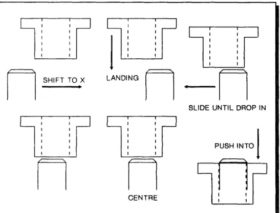
ie. the spacer is partially offset(1), nearly centred(2), or totally offset relative to the peg(3). A different search strategy must be used for each situation. To avoid the need for three positioning strategies, a deliberate positioning error is introduced so that the spacer is always offset to the right. Thus only a simple search to the left is required. This is shown schematically in Figure 1.2.
J
LANDING
n ·n
n
SHIFTTOXSLIDE UNTIL DROP IN
n n
CENTRE PUSH INTOI
Figure 1.2, Schematic of an adaptive solution
Following the deliberate offset, the two parts are brought into contact. This is detected by a change in the force level. The next step is to find the centre of the spacer relative to that of the shaft. The shaft is moved along to the left until it partially falls into the hole. This can be detected by a sudden drop in the
CHAPTER 1 STATE OF THE ART
insertion force. The movement is cqntinued until a rise in side force is detected, signifying that the far side of the spacer is in contact with the shaft. The shaft can then be moved midway between these two contact points, where the insertion phase can begin.
This approach works for loosely fitting parts only. Smaller clearances require a different strategy with the spacer tilted one way for the initial alignment phase, and then tilted back to normal again once the insertion is under way [28]. This strategy is typical of adaptive control. The force information here is not being used to its full extent, and for this application, a simple thresholding sensor is used to signal when the force exceeds a pre-set level.
Similar strategies to this have been proposed by other workers [10,19,27,29].
1.3 Special Actuators for Force Feedback Control
A common problem in the area of force feedback control is that the robot is sometimes incapable of the fine control actions required of it by the control strategy. Although a six degrees of freedom robot should have the articulation to cope with most required movements, it often incapable of small corrective movements or adjustment. The relative positioning of the parts may be improved by the application of force feedback, but the resolution of the robot is not.
In addition, the large inertia of industrial robots make them unable to perform small high speed positional movements. The calculation of jOint movement commands is lengthy. causing time delays. Lastly, most robot controllers used in industry today lack the communication and processing capability to be able to cope with sensory information [22]. Even when this information is processed by external computer, it is often not possible to communicate movement commands to the robot controllers, due to its limited communication facilities. Some researchers have devoted their attention to the development of more
accurate and more finely controlled robots. However, these tend to
be
expensive research tools and are generally not commercially available. It is argued by some workers [16,18] that this approach adversely affects the
CHAPTER 1. STATE OF THE ART
universality of a robot.
Other avenues of research use some separate device to provide controllability and high resolution. Usually the robot makes the coarser, more approximate positioning moves, while this device makes small, fine corrective motions, using between two and six degrees of freedom. This coarse/fine system allows the use of less accurate, and hence cheaper, robots. This becomes more accurate, if more expensive, with the addition of a special actuator. This sort of actuator can also be used to improve the relative pOSitioning between parts in a hard automation system.
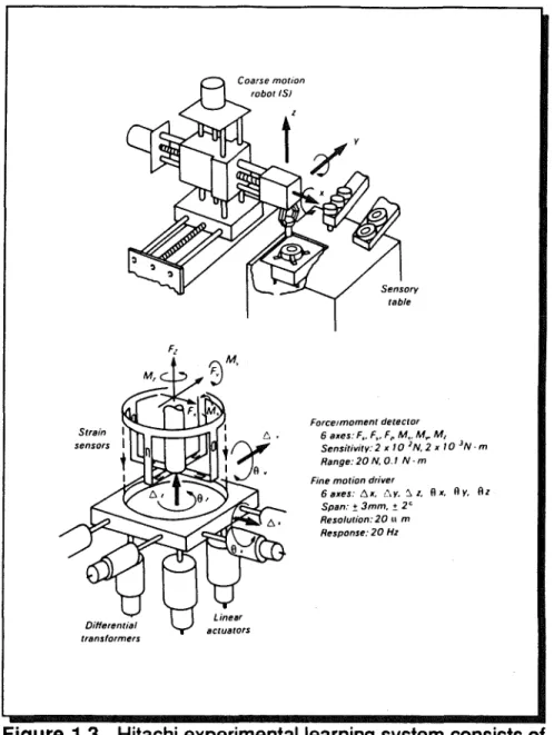
The actuator can be mounted [8,9,16,18,19,25,31,32,33,34] on "the" robot end effector or it can be positioned on a special worktable with one of the parts fixed to it [9,10,25]. One major advantage of using a wrist mounted actuator is that it can easily be applied to different makes and models of robots and does not limit the convenience of the working region of a robot: this is the method of improvement chosen for this reported research at Middlesex Polytechnic. It can also be applied to the two types of force feedback applications mentioned earlier. The advantage of mounting the actuator on the worktable is that some of the robot payload is not sacrificed and it is also very suitable for assembly. However, it does limit the effective area where feedback control can be applied. One of the earliest of these special devices was the Hitachi Hi-T-Hand which was developed as early as 1974 [34]. This robot insertion system incorporates a positioning mechanism, a tactile force sensor, and a flexible wrist. This arrangement is shown in Figure 1.3. The robot system shown comprises a main robot, an auxiliary robot, and parts supply devices. The auxiliary robot picks up the object with the hole from the parts supply and places it securely in the working pOSition. The main robot picks up the shaft and performs the insertion operation under force feedback control.
Making use of sensors in the wrist, the relative positions of the shaft and hole are detected, and these are then controlled by moving an appropriate robot axis.There are several Hi-T-hands for use in different applications.
CHAPTER 1
assembly operation.
STATE OF THE ART
Force/moment detector
6 axes: Fl' F~. F" M •. M.". M,
Sensitivity: 2 x 10 IN. 2 x 10 IN· m Range: 20 N. 0.1 N· m
Fine motion driver
6 axes: 6x. !"y. ~ z. Ax. Ay. Al Span: 1: 3mm. ±. 2c
Resolution: 20 II m
Response: 20 Hz
Figure 1.3, Hitachi experimental learning system consists of a simple robot with multi-directional force sensor on the table.
Stepourjine [6] proposed an automatic Insertion Module for light robotics. This device is attached to the robot wrist, and achieves insertion using a pre-inclination technique. Once the peg has been centred in the hole using force feedback, axis alignment is restored. This device has a remote centre through which its compliance effectively acts, and can also act as a passive device with force feedback turned off.
Vachtsevanos et al [35] proposed the novel use of a micro-manipulator which incorporates a spherical motor at the end effector of the robot. This provides
CHAPTERJ STATE OF THE ART
possibilities for combining roll, pitch and yaw motions in a single joint. Motion
in the other three axes appe~r!) to be provided by the manipulator itself. Force
sensing is achieved by monitoring the motor load, and the use of an artificial intelligence based heuristic fuzzy logic control algorithm is proposed, based on the force/position control and constrained space first presented by Aaibert and Craig [22].
Asakawa [30,31] describes VACCOM a variable compliance device which is able to absorb positioning errors. This device also incorporates force sensing, removing the need for a separate sensor.
Drazan, Hopkins and Bland [9,10,11,12,13,29] describe several different sensing/micro-manipulation stages with control strategies for assembling different components.
Another special device for insertion tasks is the Active Adaptable Compliant Wrist (AACW), developed at University of Leuven, Belgium [16,17,18,19,36]. This device is mounted at the end of the robot arm and has three translational and two rotational axes.
Purnell et al applied the force feedback control in robotic meat cutting and deboning, using database information. A robot drives a powered knife through the carcass utilising force feedback control to follow bone profiles thus removing meat from a beef forequarter[55].
1.4 Review of Literature Survey
Positioning errors in path-following and assembly operation can cause large contact forces to arise between mating parts. These may deform mating parts, and wedging or jamming can occur in assembly operation causing damage to the end effector and possibly also damaging the robot, or workstation.
The ACC device is a means of providing extra compliance in the assembly system, whilst reducing the possibility of large contact forces and the likelihood of parts wedging and jamming. As with any passive device, the ACC can only work within certain limitations, and hence there is limit to its versatility.
CHAPTER 1 STATE OF THE ART
Active force feedback provides similar force reduction abilities over a wider working range. This method varies widely in implementation and usage. Force feedback can be implemented directly on a robot. This results generally in a slow moving, relatively inaccurate, system suited for applications such as contour following, where accuracy may not be paramount.
For assembly tasks requiring fine motion force feedback, a highly accurate micro-manipulator is necessary to increase the basic accuracy of the robot system. Such a micro-manipulator should be of low mass, thus allowing high speed corrective motions to the path of the end effector.
Although this literature search has reviewed numerous methods for implementing force feedback, all the control algorithms used so far are quite simple ones and lack the benefit of any controlling "intelligence" of the task in hand. This comment has been made by several workers in the field, notably Witney [54]. Many insertion algorithms use, at times, a trial and error control policy in the area where the relationship between forces and positional errors becomes ambiguous.
In a situation where forces are to be reduced there exists the problem that, if the forces become zero, there will be insufficient information to guide the movements of the robot end effector. In addition to this there can be times during the peg-in-hole assembly task when the direction of the force vector becomes impossible to ascertain using standard techniques so that good control of the system is difficult.
These factors suggest that it is not possible to rely solely on current force levels to generate the control strategy and it is here that more advanced control techniques are necessary.
1.5 Re-Appraisal of Aims
This literature survey has revealed numerous implementations of force feedback techniques, and it would appear that some specialised micro-manipulation device is usually employed to effect force reduction in peg-in-hole insertion tasks. Most of the control algorithms used seem simple and are often
CHAPTER 1 STATE OF THE ART
error driven and yet, judging by the large amount of research In this field, a simple human task like peg-in-hole assembly is a highly complicated task in automated assembly. More complex control algorithms are needed to eliminate the trial and error approach described in the literature for use in the region where the force/position relationship becomes ambiguous. This justifies the first aim of this work, which is to develop algorithms capable of reducing contact forces during insertion and in the path following.
An area of research that has not been addressed is that of developing a control algorithm capable of doing peg-in-hole assembly and also of following a specified path. As far as it is known, no attempts have been made to consider robotic force control in general in order to discover common elements that may exist in a variety of such tasks. This justifies the second aim of this work. Thirdly, an attempt was made to identify and categorise most of the factors (if not all) affecting robot performance and suggesting improvement techniques. The significance of this analysis is that robot users can now determine the combination of error sources that have the most influence on the performance of a robot being characterised.
CHAPTER 2 FACTORS AFFECTING ROBOT ...
2.0 Factors Affecting Robot Performance Accuracy
Factors affecting robot accuracy are identified in this section. Several methods for the improvement of robot accuracy are discussed. It is importantthat users of robots understand the factors affecting accuracy and where present technology stands in making accuracy improvements.
Robot accuracy can be influenced by a number of factors. They are classified into the following categories:
(i) "Environmental" factors, such as temperature, humidity and electrical noise;
(ii) "Parametric" factors, including kinematic parameters such as robot link lengths, joint zero-reference angles, dynamic parameters such as structural compliance, drive-train compliance, friction parameters, varying inertia, and other non-linearities such as hysteresis, backlash etc.; (iii) "Measurement" factors, such as resolution and non-linearity of encoders, resolvers etc.;
(iv) "Computational" factors, such as robot path computation errors from digital computer round-off, steady-state control error and etc.;
(v) "Application" factor, such as installation errors, part presentation errors, errors in defining workpiece coordinate frame etc.;
Each category of inaccuracy may not be totally independent from the others. For instance, temperature change affects link length, friction coefficients, drifts in control electronics and measurement sensitivity, etc.
2. 1
Environmental FactorsTemperature variations can cause link length changes in structural components and drive-train components. For instance, a change of 10 degrees Fahrenheit (typical from day to night in plant environment) will cause a 1000 mm aluminium structure to change by (1000mmxO.13E-4x10=) 0.13mm. With the same temperature change a 600 mm steel ball screw can change length by (600
CHAPTER 2 FACTORS AFFECTING ROBOT ...
mmxO.08E-4x10=) 0.048 mm and if the distance of the end-effector is 8 times that of the moment arm of the ball screw, the resulting actual change of end-effecter position can be 0.384 mm. In some applications this change is acceptable but in others, requiring precision, this may not be tolerable. Temperature affects long-term repeatability and accuracy and needs to be carefully considered in robotic applications.
Temperature and relative humidity affect characteristics of lubricants used in drive trains. Common lubricants used in robots are non-Newtonian and their rheology behaviour depends on how they have been used. The amount of lubricants on the drive elements varies depending on design and service conditions. It is normally difficult to achieve a reliable measurement of frictional characteristics in working industrial robots. Temperature variations affect dimensions of rotating parts of rotary drives and these in turn cause changes in friction, Coulomb friction and viscous friction values. Clearance in drive train components and hysteresis characteristics are similarly affected. Such friction related factors affect the accuracy of robots and cause difficulties in control. Fibre-reinforced composite materials are sometimes used in robot structures. By combining fibres of different coefficients of thermal expansion, an arm can be designed so that there is little effective change of arm length within a range of temperature. This is one possible solution in designing extremely accurate robots. However, resins used in fibre-reinforced composite material are also subject to changes in chemical composition within the working environment of the robot, e.g. in an extremely acidic or caustic environment, the structural rigidity of a fibre-reinforced composite arm can suffer.
Typically, a robot controller contains a number of analogue parts such as resistors, capacitors and operational amplifiers. There can be slight drifts in characteristics of these electronic components that nominally do no harm at all. However, they may contribute several "counts" of offset values in each joint of the robot when ambient temperature varies or electrical noise is randomly injected. For a typical resolution of 0.001 mm per encoder count, a drift of 10 counts can mean 0.01 mm at end effector, and the cumulative drift from several joint axes can be several times greater then 0.01 mm.
CHAPTER 2 FACTORS AFFECTING ROBOT ... .
2.2 Parametric Factors
Robot parametric factors include kinematic parameters and dynamic parameters. Inaccurate representations of robot parameters contribute to robot theoretically predicted inaccuracy. Generally, kinematic parameters affect "pose" accuracy and dynamic parameters affect "trajectory" accuracy.
2.2. 1 Kinematic Parameters
The most noticeable kinematic parameters are robot link length parameters. Link lengths are normally specified by design. They can vary due to environmental factors and due to manufacturing and assembly errors. A link
length can be different from its normal value due to machining tolerance and
tolerance stack-ups from a number of sub-assemblies. For each machined piece of a structure, machining tolerance is generally around ±O.05 mm. If a robot link were to be assembled from three pieces fastened together, overall length of the link due to tolerance stack-ups couid vary by ±O.05 mmxSQRT 3 i.e. O.085mm RMS. For a three-jointed robot, end-effector position could then
vary by ±O.085 mmx3 i.e. ±0.255 mm which would be a relatively significant
amount of error for many robot applications. Quality inspection and retrofit at final stage of machining will help reduce such error. It would add cost to the robot components if accuracy were so desired.
Kinematic parameters include offset distances between each pair of adjacent joint axes. Offset distances can be different from nominally designed values by a similar amount as indicated in the last paragraph. When assembling robot manipulators, some link lengths or drive shaft lengths are slightly modified to make all pieces fit together. With careful design and precision machining many of the "fitting" tasks can be reduced in sub-assemblies but not totally eliminated in final assembly of the entire machine.
Angularity between each pair of adjacent axes also contributes to inaccuracy of the robot. Angularity can result from assembly error when fitting sub-assemblies together, or error in the seating of bearings supporting the axes. Just an error of 0.1 degree in angularity could cause a link offset error of 1.745
CHAPTER 2 FACTORS AFFECTING ROBOT ...
Many industrial robots in use today.adopt the design of a so called "ideal" robot [37,38]. "Ideal" robots have closed-form inverse solutions such that desired Cartesian motions of robot end-effector can be converted to joint angle commands directly. This allows fast computation in the robot controller so that robots can follow desired programmed paths in real-time. Typical "ideal" robots contain three adjacent axes of rotation which intersect at a common point or at infinity (in this case, the three adjacent axes are parallel). Realistically, errors caused by kinematic factors due to manufacturing and environmental factors often make "ideal" robots non-ideal, thus affecting accuracy.
The other kinematic parameters that contain inaccuracy are the zero-angle position of robot joints. The zero-angle position of each joint can contain errors due to imprecise seating of encoder/resolver, or improper procedure in determining the zero-angle position. As stated before, an error of 0.1 degree in defining zero-reference angle can cause an inaccuracy of 1.745 mm at 1 OOOmm away from the centre of that particular axis. Whereas all the kinematic parameters contribute to errors in accuracy, they generally do not contribute error in repeatability.
Drive-train errors include non-uniformity of belts, chains, gears and lever mechanisms in their range of motion. They cause inaccuracy in the workspace of robot. Belts and chains by their vary nature are elastic and there will be inaccuracies associated with the extension of the belt and chain when power is transmitted. Gears introduce backlash into the transmission system which will cause inaccuracies once the direction of rotation is reversed. The error is a cumulative one and will increase as the gears wear. Lever mechanisms may introduce large backlashes into the system. This is a result of the necessity for clearance fits for freedom of movement. In order to improve the performance of the robot, more accurate, finer and more selective power transmission system can be employed to minimise the effects of joint clearances. These, including hardware techniques for improving the system anti-backlash mechanism and so greatly improving the performance characteristics. However, this significantly increases the cost of the robot. Also, by careful measurements of gear train motions, gear train error can be mapped in robot software for accuracy improvement [39].
CHAPTER 2 FACTORS AFFECTING ROBOT ... 2.2.2 Dynamic Parameters
Structurally, robots are designed to be more flexible than machine tools, otherwise robots can become heavy and inefficient. Being flexible, robots will deflect under load and under their own weight. There are several components of robots that contribute to flexibility, i.e. 1) bearings, 2) drive train components and 3) link structures. Each one of these three components (structure, bearing, drive-train) can contribute as much significant flexibility as that of the other two, depending on the particular design of robot mechanism. There is no fixed rule in determining flexibility values for industrial robots. All the above components contribute to robot inaccuracy when payload changes at the robot end-effector. Bearings are usually designed not only to carry loads at desired speeds with given life, but also to have small angular deflection under moment loading.
Drive-train components are designed with overall stiffness to be within a
reasonable value. Links are usually designed with cross section either box-shaped or I-box-shaped to maximise their sectional moduli of ,elasticity. links are subject to bending under dynamic and static loads. Thus the end-effector will deviate from its expected position an amount proportional to the sum of the dynamic and static factors. The forces will vary as the robot accelerates and decelerates the payload and there will be a degree of dynamic oscillatory error. To reduce deflections caused as a result of dynamic and static loads the effective link stiffness must be increased. This may be achieved simply by increasing the cross-sectional second moment of area. Unfortunately as the cross-section of area is increased the mass of the link will increase, resulting in a loss of performance in terms of speed and increased inertia effects and possible overshoot problems. The link stiffness can be increased using materials possessing the following characteristics for use in robot operations
:-1) High strength to mass ratio, 2) High stiffness to mass ratio, 3) Low inertia,
CHAPTER 2 FACTORS AFFECTING ROBOT ... .
5) Good hostile environment resistance.
Composite materials prepared appropriately possess the above properties and are ideal for robot structures. It should be noted that composite fibre material linkages will reduced beam bending but will not eliminate it entirely. Thus some positioning error due to beam bending as well as amplification of encoder measurement errors will still exist.
One way to reduce bending of the robot links is through the concept of "local support" [56]. Since robots are designed for large ranges of motion, significant bending moments are created, especially when the manipulator is fully extended. In order to reduce this large moment arm, the robot can attach itself to a local support in the vicinity of the task location. After completing the operation, the robot would detach itself and move on to the next operation where it would again attach itself to another local support. Thus, there would be several local supports in the work space, located near every critical operation. Large bending moments on robot linkages can be eliminated by attaching the robot to local supports within the working zone. There are many advantages to be gained using this idea; bending is virtually eliminated and since the position of the support will be accurately defined in relation to the workpiece the absolute pOSition of the end point will be known. Unfortunately the major requirement for the use of robots is the flexibility they afford and the use of local supports would significantly restrict robot flexibility.
The use of composite materials and/or local support are passive solutions to the beam bending problem. A possible active solution is that of "Active Stiffness Control" for each link [33,40]. If the amount of bending was known for each link then it would be possible to compensate for it, using links comprising of an outer and inner beam with perpendicular actuators. Bending of the outer beam may be detected by strain gauges suitably placed on each beam or link of the robot. An appropriate actuator could then generate a forced between the outer and inner beams, necessary to eliminate beam bending errors. The end point displacement would in effect be eliminated by a closed loop active stiffness control system.
The system described is valuable solution- but has a number of drawbacks.
CHAPTER 2 FACTORS AFFECTING ROBOT ...
firstly measuring errors and errors associated with the drive, such as backlash in gears, etc., are still present. Secondly if a fast control system is to be implemented for real time compensation control then the dynamic
characteristics of each link must be well known. Thirdly there is increased
complexity and thereby cost considerations. Finally the inertia of links would be significantly increased making accurate control of the end-effector difficult. Inertial parameters of robots play a role in trajectory accuracy and velocity accuracy of robots. Since the power drives of robots, such as electric motors, do not provide instantaneously infinite power and are torque limited, inertial parameters contribute to centripetal, tangential and Coriolis forces that make robot controls challenging. Inertial parameters are usually not precisely measured in robot manipulators. Castings of structural parts could vary in thickness. Machining of casting could be offset if the starting reference dimension is offset. Heat from welding could cause slight distortion of parts. All such factors cause variations of inertial parameters from their originally designed values. Inertial parameters could vary by 10% or more from robot to robot of the same model. Usually measurements of inertial parameters are difficult and costly. Off-diagonal terms of the inertial matrix are especially difficult to obtain. Inaccurate inertial parameters can cause control errors. With inertia J and flexibility (second moment of area 1/ radius of gyration k) in a dynamic system, resonance or natural vibration is a problem to be overcome. Every machine has frequency resonances and every robot shakes at or near its natural frequencies. Typical industrial robots have their first resonance at about 20 Hz, and a large majority of industrial robots have their first harmonic at less than 5 Hz [57]. Depending on the speed and direction of drives, resonances may cause problems in accuracy and in life of components. Friction parameters of robots are difficult to quantify accurately. In a typical non-direct drive gear train, only 50% to 90% power is delivered from the output of the motor shaft to the final driven joint: the rest is lost through friction as heat. Proper lubrication reduces friction, improves efficiency, and increases life of drive train components. Viscous friction is one of the many forms of friction to be overcome. In robot drive systems, friction is normally evident, especially in
CHAPTER 2 FACTORS AFFECTING ROBOT ... .
large drives carrying a high payload. Hysteresis shows up when the drive is cycled back and forth. thus contributing errors in multi-directional repeatability and accuracy. Coulomb friction is a function of normal force exerted between two contacting surfaces. All friction parameters dissipate energy and contribute to robot inaccuracy.
2.3 Measurement Factors
Encoders and resolvers are the most common position feedback devices for robots. Other position feedback devices include inductosyn, LVDT, etc .. They provide resolutions from several hundred counts to several hundred thousand counts per revolution. Encoders and resolvers can be mounted directly onto the motor shaft or the joint.
Encoders mounted directly to the motor provide ease of control of the motor since motor communication is controlled directly. However, flexibility, backlash and other parametric factors affecting robot accuracy are not directly fed back to the robot controller. Thus end effector accuracy is not controlled because the absolute and point position is derived from the various joint displacements. If there is a slight measurement error associated with the encoders, it is greatly amplified through the length of each link, resulting in a large end effector position error. Encoders mounted directly to joint axes will require high resolution to detect small increments of joint positions. Compliance of drive train between motor and rotated joint can affect robot performance and accuracy, especially at the high loads.
Sensors such as strain gauge devices can be mounted at appropriate places on robot links to measure strain changes so that robot flexibility can be accurately controlled. End effector inaccuracy could be reduced by using such methods. Load sensing helps monitor machine tool conditions and can be similarly used in monitoring robot conditions [41]. It detects loads which can be used for flexibility compensations. However, all sensors are resolution-limited and if accuracy were to be improved, resolution of measurement devices would
need to be better than the required accuracy.
CHAPTER 2 FACTORS AFFECTING ROBOT ...
2.4 Computation Factors
The desired path of a robot end effector is calculated in a robot controller. Precise commands to individual joints are then issued. This path computation takes time. In today's industrial robots it can range from several milliseconds to several hundred milliseconds. Computations of paths contain several types of error. The computer controller uses a finite number of bits to represent
numbers. For most computations, 16 bits will be enough to retain precision in
robot path computations. For computations that contain an accumulation of small increments of motions, there can be inaccuracy due to round-off errors. For instance [42], a motor shaft attached to a ball screw may have a resolution of 1000 counts per revolution. This ball screw is used to rotate an arm hinged at one end. If the pitch of the ball screw is 10 mm per revolution, finite resolution of the ball screw position is then 0.01 mm per count. Since the length of this ball screw is used to control angular motion of the arm, actual resolution of the angle spanned by the ball screw is about (0.01 mm/La) radian, where La=length of moment arm. If the length is about 250 mm, actual resolution of angle is about 0.00004 radian per count. For a total range of travel of 1.2 radian, a total of 30,000 counts is required, enough for a 16 bit representation of angles. However, actual angle computed from the ball screw travel comes from the cosine formula. From computations of square roots and arcosine, it is likely to lose one count of theta due to round-off. After several cycles of the ball screw, actual position of the robot arm can be "off" by several counts. This example is meant to illustrate the general round-off or truncation error. Increasing the number of bits to represent numbers will help to reduce or eliminate such round-off error.
Another factor contributing to inaccuracy of robots is the case of the "non-ideal" arm. Typical computations of robots use direct formulations which assume ideal robot kinematics. In reality arms are seldom built with ideal kinematics even though they are so designed. This error is in the range of manufacturing tolerance which can be in the order of a tenth of a millimetre. In order to reduce error due to a non-ideal robot arm, robot kinematic computation needs to be done using non-ideal formulations. Non-ideal formulations require much more
CHAPTER 2 FACTORS AFFECTING ROBOT ... .
computation than today's robot controllers can handle. Algorithms using numerical iterative approaches to handle non-ideal robot configurAtions can be developed [43], but real-time general solutions are needed to overcome error due to "non-ideal" robots. Robot positions at or near robot singularities present challenges in computations. There are many ways to handle singular positions in robot manipulators. Very often, accuracy is slightly compromised near such singular positions in order to achieve stable motions.
2.5 Application Factors
Besides the above-mentioned factors affecting robot accuracy, actual applications of robots also contribute to inaccuracy of the system. The main reason for demanding accuracy in the first place is the need to be able to perform the specific job or application. Besides accuracy of robots, factors
related to the application need to be looked into.
The first application factor concerns installation. Some robots are installed on rather soft surfaces. Some are installed by grouting on the cement floor. It is essential that a robot to have a firm foundation.
The next factor relates to dimensional integrity of the workpiece. Due to tolerance stack-ups and other manufacturing errors of the workpiece, the demand to perform is often unduly placed on the robot. It may just need a simple correction of the workpiece design and manufacturing procedure to allow the entire robot system to perform accurately.
End-of-Arm tooling inaccuracy is another factor contributing to overall robot inaccuracy. Like manufacturing errors in robot parameters, tooling design/manufacturing/installation also contain errors. Sometimes it may be less costly and more effective to improve the accuracy of end-of-armtooling rather than the robot.
--
3
Q)
-g
s
()
.
n
OCD
.~
n
<
·
I
c:::
_.:::r
-a
-t:::J
0
Q)tC
C.
~
n-t
fn
9i
<00
c::r
I,
(,.)
0
,
I
CHAPTER 3 METHODS OF IMPROVING ...
3.0 Methods of Improving Robot Accuracy
After looking over factors affecting robot accuracy, it may seem alarming that robots can be quite inaccurate. It is generally true that inaccuracy exists, but there have been many methods developed by users, manufacturers and researchers to make improvements for intended applications. Quality inspection with particular attention to accuracy will reduce errors in manufacturing and assembly and there is a general need to provide an environment for consistent robot accuracy.
Obviously, robot users and manufacturers will constantly strive to make
improvements in robot accuracy. Some of the methods which may be used for
improving robot accuracy are discussed in the following three categories: (i) Calibration methods, including many of the existing methods of calibration, with coordinate frame reference matching techniques. They generally improve robot accuracy at only one particular point in the robot workspace. They may result in an improvement termed a "first-order" improvement in robot accuracy.
(ii) Open-loop methods, including many of the robot parameter identification methods in use or in development. Many of the identification techniques deal With kinematic parameter identification. Drive train errors and compliance errors have also been investigated with good results. Open-loop methods depend on off-line measurements to identify the necessary parameter corrections. After Identification of error, the corrected parameters are used by
robot controllers In open-loop computation of robot paths. These methods do
provide another order of improvement over calibration methods as accuracy for the robot workspace can be enhanced. Dynamic identification and control require computations that are not yet economically attainable in most industrial robots.
(iii) Closed-loop methods, including methods that incorporate external sensors that detect end-effector positions, integrated on-line with robot controllers, also provide another order of improvement: the pose of the end effector is fed back to the robot controller on-line and an additional control loop