Multi-Function Module
IM 01W03E01-01EN
Contents
1.
Introduction ... 1-1
1.1 Safe Use of This Product ...1-2 1.2 Warranty ...1-2
2.
Notes on Handling ... 2-1
2.1 Check the Model Name and Configuration ...2-1 2.2 Transport ...2-1 2.3 Storage ...2-2 2.4 Selecting the Installation Location ...2-2 2.5 Use of a Transceiver ...2-3 2.6 Installation of an Explosion Protected Instrument ...2-3
2.6.1 FM Approval (United States) ...2-4 2.6.2 FM Approval (Canada) ...2-10 2.6.3 ATEX Certification ...2-16 2.6.4 IECEx Certification ...2-16
3.
Component Names ... 3-1
4.
Installation ... 4-1
4.1 Precautions ...4-1 4.2 Mounting ...4-1 4.2.1 Installation of FN110 ...4-1 4.2.2 Mounting of FN510 ...4-25.
Wiring ... 5-1
5.1 Notes on Wiring ...5-1 5.2 Cable Selection ...5-1 5.3 Installation and Connection of FN110 ...5-25.3.1 Installation of FN110 ...5-2 5.3.2 Connection of FN110 ...5-3
5.4 Connecting Input Signal Cable ...5-3
5.4.1 Connecting Input Terminal and Grounding Terminal ...5-3
5.5 Grounding ...5-6
6.3 Connecting to the Field Wireless Network ...6-2 6.4 Display Contents of the Integral Indicator ...6-4 6.5 Shutting Down ...6-4
7.
Setting Parameters ... 7-1
7.1 Preparation for Parameter Setting ...7-1 7.2 Preparing Software ...7-1
7.2.1 Softwares for the Field Wireless Configuration Tool and the Device Configuration Tool ...7-1 7.2.2 Software Download ...7-1
7.3 Setting Parameters ...7-2
7.3.1 Parameter Usage and Selection ...7-2 7.3.2 Function Block and Menu Tree ...7-3 7.3.3 Parameters for Wireless Communication ...7-7 7.3.4 Tag and Device Information ...7-7 7.3.5 Setup the Integral Indicator ...7-7 7.3.6 Sensor Type ...7-7 7.3.7 Parameters for Function ...7-8 7.3.8 Write Protect ...7-8 7.3.9 Switching to the Deep Sleep Mode ...7-8 7.3.10 Switching to the Silence Mode ...7-9
7.4 Self-Diagnostics ...7-10
7.4.1 Identify Problems by Using the Device Configuration Tool ...7-10 7.4.2 Alert Report ...7-10 7.4.3 Checking with Integral Indicator ... 7-11
8.
Maintenance ... 8-1
8.1 General ...8-1 8.2 Recommended Products List ...8-1 8.3 Replacing the Battery Pack ...8-1 8.4 Replacing the Batteries ...8-3 8.5 Handling Batteries ...8-3 8.6 Switching LCD Display ...8-4 8.7 Replacing the FN110 ...8-5 8.8 Replacing the FN510 ...8-5 8.9 Replacing the Connected Device ...8-5 8.10 Troubleshooting ...8-5
8.10.1 Basic Troubleshooting Flow ...8-5 8.10.2 Example of Troubleshooting Flow ...8-6 8.10.3 Errors and Countermeasures ...8-7
10.3 Optional Specification (For Explosion Protected Type) ...10-4 10.4 Optional Specifications ...10-5 10.5 Optional Accessories ...10-5 10.6 Dimensions ...10-5 10.7 LCD Display Character List ...10-7
This manual describes how to use the FN510 Field Wireless Multi-Function Module (hereafter simply referred to as FN510).
FN510 was precisely calibrated at the factory before shipment. To ensure both safety and efficiency, please read this manual carefully before you operate this product.
FN510 works by utilizing the FN110 Field Wireless Communication Module (hereafter simply referred to as FN110). Please attach FN110 before use. Table1.1 summarizes the related document list of this manual.
Table 1.1 Related Document List
Title Document No.
FieldMate
Versatile Device Management Wizard
User’s Manual IM 01R01A01-01E
YFGW710
Field Wireless Integrated Gateway
User’s Manual IM 01W01F01-01EN
YFGW410
Field Wireless Management Station
User’s Manual IM 01W02D01-01EN
FN110
Field Wireless Communication Module
General Specifications GS 01W03B01-01EN Regarding This Manual
• This manual should be provided to the end user.
• The contents of this manual are subject to change without prior notice.
• All rights reserved. No part of this manual may be reproduced in any form without Yokogawa’s written permission.
• Yokogawa makes no warranty of any kind with regard to this manual, including, but not limited to, implied warranty of merchantability and fitness for a particular purpose.
• If any question arises or errors are found, or if any information is missing from this manual, please inform the nearest Yokogawa sales office.
• The specifications covered by this manual are limited to those for the standard type under the specified model number break-down and do not cover custom-made products.
• Please note that changes in the specifications, construction, or component parts of this product may not immediately be reflected in this manual at the time of change, provided that postponement of revisions will not cause difficulty to the user from a functional or performance standpoint.
• Yokogawa assumes no responsibilities for this product except as stated in the warranty. • If the customer or any third party is harmed by
the use of this product, Yokogawa assumes no responsibility for any such harm owing to any defects in the product which were not predictable, or for any indirect damages. • The following safety symbols are used in this
manual:
WARNING
Indicates a potentially hazardous situation which, if not avoided, could result in death or serious injury.
CAUTION
Indicates a potentially hazardous situation which, if not avoided, may result in minor or moderate injury or physical damage. It may also be used to alert against unsafe practices.
IMPORTANT
Indicates that operating the hardware or software in this manner may damage it or lead to system failure.
NOTE
Draws attention to information essential for understanding the operation and features.
this product. If these instructions are not heeded, the protection provided by this product may be impaired. In this case, Yokogawa cannot guarantee that this product can be safely operated. Please pay special attention to the following points:
(a) Installation
• This product may only be installed by an engineer or technician who has an expert knowledge of this product. Operators are not allowed to carry out installation unless they meet this condition.
• With high process temperatures, care must be taken not to burn yourself by touching this product or its casing.
• All installation shall comply with local installation requirements and the local electrical code.
(b) Wiring
• This product must be installed by an engineer or technician who has an expert knowledge of this product. Operators are not permitted to carry out wiring unless they meet this condition.
(c) Maintenance
• Please carry out only the maintenance procedures described in this manual. If you require further assistance, please contact the nearest Yokogawa office.
• Care should be taken to prevent the build up of dust or other materials on the display glass and the nameplate. To clean these surfaces, use a soft, dry cloth.
• The use of this instrument is restricted to those who have received appropriate training in the device.
• Take care not to create sparks when accessing the instrument or peripheral devices in a hazardous location.
• Repair or modification to this instrument by customer will cause malfunction of explosion protect function and hazardous situation. If you need to repair or modification, please contact the nearest Yokogawa office.
(e) Modification
• Yokogawa will not be liable for malfunctions or damage resulting from any modification made to this product by the customer.
1.2 Warranty
• The warranty shall cover the period noted on the quotation presented to the purchaser at the time of purchase. Problems occurring during the warranty period shall basically be repaired free of change.
• If any problems are experienced with this product, the customer should contact the Yokogawa representative from which this product was purchased or the nearest Yokogawa office.
• If a problem arises with this product, please inform us of the nature of the problem and the circumstances under which it developed, including the model specification and serial number. Any diagrams, data and other information you can include in your communication will also be helpful.
• The party responsible for the cost of fixing the problem shall be determined by Yokogawa following an investigation conducted by Yokogawa.
- Improper and/or inadequate maintenance by the purchaser.
- Malfunction or damage due to a failure to handle, use, or store this product in accordance with the design specifications. - Use of the product in question in a location
not conforming to the standards specified by Yokogawa, or due to improper maintenance of the installation location.
- Failure or damage due to modification or repair by any party except Yokogawa or an approved representative of Yokogawa. - Malfunction or damage from improper
relocation of the product in question after delivery.
- Reason of force majeure such as fires, earthquakes, storms/floods, thunder/ lightening, or other natural disasters, or disturbances, riots, warfare, or radioactive contamination.
Trademarks
In this document, trademarks or registered
trademarks are not marked with “™” or “®”. Product names and company names in this document are trademarks or registered trademarks of the respective companies.
Authorized Representative in the EEA
The Authorized Representative for this product in the EEA is: Yokogawa Europe B.V.
Euroweg 2, 3825 HD Amersfoort, THE NETHERLANDS.
When the FN510 delivered, check the appearance for damage, and also check that the mounting parts shown in Figure 2.1 are included with your shipment. If “No Mounting Bracket” or “Horizontal connection” is indicated, no mounting bracket is included.
Bracket fastening bolt
FN510
mounting bracket U-bolt nut
FN510 fastening bolt Spring washer Bracket fastening nut U-bolt F0201.ai
Figure 2.1 FN510 Mounting Hardware Table 2.1 FN510 Mounting Hardware
Item Qty
FN510 mounting bracket 1
FN510 fastening bolt 4
Bracket fastening bolt 2
Bracket fastenig nut 2
Spring washer 2
U-bolt 1
U-bolt nut 2
• User’s Manual (IM01W03E01-01EN) • FN510 mounting hardware
When specified mounting bracket. • Protection cap (optional specifications) • Wired tag plate(optional specifications)
2.1 Check the Model Name and
Configuration
The model name and configuration are indicated on the nameplate. Verify that the configuration indicated in the “Model and Suffix Code” in subsection 10.2 is in compliance with the specifications written on the order sheet. Manual number omitting the language code at the end is printed on the nameplate.
F0202.ai
Figure 2.2 Nameplate
MODEL : Specified model code. SUFFIX : Specified suffix code. STYLE : Style code.
S/N : Serial number.
DATE : Date of manufacture. SUPPLY : Supply voltage.
TOKYO 180-8750 JAPAN: The manufacturer name and the address *1.
*1 “180-8750” is a zip code which represents the following address. 2-9-32 Nakacho, Musashino-shi, Tokyo Japan
2.2 Transport
To prevent damage while in transit, leave the FN510 in the original shipping container until it reaches the installation site. For transportation of batteries, refer to subsection 8.5 “Handling Batteries”.
1. Chose a storage location that satisfies the following requirements.
• A location that is not exposed to rain or water. • A location subject to a minimum of vibration
or impact.
• The following temperature and humidity range is recommended. Ordinary
temperature and humidity (25°C, 65%) are preferable.
Temperature: -40 to 85°C Humidity : 0 to 100% RH
(no condensation)
2. If at all possible, store the FN510 in factory-shipped condition, that is, in the original shipping container.
3. Preferably remove the batteries for storage. For maximum battery life, the storage temperature should not exceed 30°C.
NOTE
When storing FN510 with a battery pack, it is recommended to put the FN510 in Deep Sleep mode to conserve the batteries. For details on how to switch to Deep Sleep mode, refer to subsection 7.3.9 “Switching to the Deep Sleep Mode”.
Although this product is designed to operate in a harsh environment, to maintain stability and accuracy, the following is recommended.
Wireless Communication
NOTE
The installation location of this product must meet the following conditions:
• Install this product to be perpendicular to the ground.
• When using a remote antenna cable, regardless of the installing direction of the FN510, install the FN110 to be perpendicular to the ground.
• Install the FN110 at least 1.5 m above the ground or floor.
F0203.ai
1.5m or more
• Ensure that there are no obstacles such as walls or pipes within a 30 cm radius of the FN110.
• Confirm that each field wireless equipment can see the antenna of other devices which locate within its own communication range.
protection system or appropriate ventilation is recommended.
Environmental Requirements
Do not allow FN510 to be installed in a location that is exposed to corrosive atmospheric conditions. When using this product in a corrosive environment, ensure the location is well ventilated.
The unit and its wiring should be protected from exposure to rainwater.
Impact and Vibration
It is recommended that the FN510 be installed in a location that is subject to a minimum amount of impact and vibration.
Installation of Explosion Protected Products
An explosion protected products is certified for installation in a hazardous area containing specific gas types. See subsection 2.6 “Installation of an Explosion Protected Instrument”.
2.5 Use of a Transceiver
IMPORTANT
Although FN510 has been designed to resist high frequency electrical noise, if a radio transceiver is used near the FN510 or its external wiring, the FN510 may be affected by high frequency noise pickup. To test this, start out from a distance of several meters and slowly approach the FN510 with the transceiver while observing the measurement loop for noise effects. Thereafter use the transceiver outside the range where the noise effects were first observed.
2.6 Installation of an Explosion
Protected Instrument
If a customer makes a repair or modification to an intrinsically safe instrument and the instrument is not restored to its original condition, its intrinsically safe construction may be compromised and the instrument may be hazardous to operate. Please contact Yokogawa before making any repair or modification to an instrument.
generation of electrostatic charge, such as rubbing surface of the product with a dry cloth.
• To satisfy IP66,
- Connect to a connector JR13WPI-5P (Hirose Electric) and tightened with a specified torque.
- Apply waterproof glands to the electrical connection port, at models FN510-xx-x00, FN510-xx-x01, and FN510-xx-x02. • The instrument modification or parts
replacement by other than an authorized representative of Yokogawa Electric Corporation is prohibited and will void the certification.
• When replacing the battery pack, be sure to minimize the risk of explosion from electrostatic discharge. Avoid any actions that cause the generation of electrostatic charge, such as rubbing surface of the battery pack and product with a dry cloth.
CAUTION
• This instrument has been tested and certified as being intrinsically safe. Please note that severe restrictions apply to this instrument’s construction, installation, external wiring, maintenance and repair. A failure to abide by these restrictions could make the instrument a hazard to operate.
• Be careful to make sure that an intrinsically safe apparatus, intrinsically safe devices, and wiring to connect them are arranged so that current and voltage are not induced by electromagnetic or electrostatic induction in the intrinsically safe circuit in order to prevent impairment of the intrinsically safe and explosion protected performance of the intrinsically safe circuit.
Caution for FM Approval (US) Intrinsically safe type. Note 1. Model FN510 Field Wireless Multi-Function
Module with optional code /FS17 for potentially explosive atmospheres: • Applicable Standards:
Class 3600:2011, Class 3610:2010, Class 3810:2005, ANSI/ISA-60079-0-2013, ANSI/ISA-60079-11-2014, NEMA 250-2003, ANSI/IEC-60529-2004 (R2011)
• Intrinsically safe for Class I, II, III, Division 1, Groups C, D, E, F & G, Class I, Zone 0, in Hazardous Locations, AEx ia IIB
• Enclosure: Type 4X and IP66 • Temperature Class: T4
• Ambient Temperature: –40 to 70 °C (–40 to 158 °F)
• For connection to Class I, II, III, Division 1, Groups A, B, C, D, E, F & G, Class I, Zone 0, in Hazardous Locations, AEx ia IIC
Note 2. Electrical Parameters (Refer to the Control Drawing) Note 3. Installation
• Installation should be in accordance with local installation requirements. (Refer to the Control Drawing)
• Be sure to use the specified battery pack and batteries. For details, refer to section 8.5 “Handling Batteries.”
• With an intrinsically safe Products, the battery pack is replaceable in a hazardous area. During the replacement work, make sure that dust and water droplets do not enter inside the products. For details on how to replace the battery pack, refer to section 8.3 “Replacing the Battery Pack.”
2.6.2 FM Approval (Canada)
(1) Technical Data
Caution for FM Approval (Canada) Intrinsically safe type.
Note 1. Model FN510 Field Wireless Multi-Function Module with optional code /CS17 for potentially explosive atmospheres: • Applicable Standards: CAN/CSA-C22.2 No. 0-10 (R2015), CAN/CSA-C22.2 No. 94.1-07 (R2012), CAN/CSA-C22.2 No. 94.2-07 (R2012), CAN/CSA-C22.2 No. 60079-0:11, CAN/CSA-C22.2 No. 60079-11:14, CAN/CSA-C22.2 No. 60529-05 (R2015), CAN/CSA-C22.2 No. 61010-1-12
• Ex ia [ia IIC] IIB T4 Ga
• Intrinsically safe for Class I, II, III, Division 1, Groups C, D, E, F & G
• Enclosure: Type 4X and IP66 • Temperature Class: T4
• Ambient Temperature: –40 to 70 °C (–40 to 158 °F)
• For connection to Class I, II, III, Division 1, Groups A, B, C, D, E, F & G
Note 2. Electrical Parameters (Refer to the Control Drawing) Note 3. Installation
• Installation should be in accordance with local installation requirements.
• DANGER POTENTIEL DE CHARGES ÉLECTROSTATIQUES
- QUAND LE MATÉRIEL EST UTILISÉ DANS DES ENDROITS DANGEREUX, ÉVITER TOUTE ACTION QUI GENERENT CHARGES ELECTROSTATIQUES, COMME FROTTANT AVEC UN CHIFFON SEC • QUAND LE MATÉRIEL EST UTILISÉ DANS
LA ZONE 0, IL DOIT ÊTRE INSTALLÉE TELLE QUE, MÊME EN CAS D’INCIDENTS RARE, SOURCES D’ALLUMAGE DUE AUX IMPACTS ET SPARKS FRICTION EST EXCLUE
• POUR ÉVITER ALLUMAGE DES ATMOSPHÉRES INFLAMMABLES OU COMBUSTIBLES, LISEZ,
COMPRENDRE ET RESPECTER ELS PROCÉDURES D’ENTRETIEN DU CONSTRUCTEUR
• UTILISER UNIQUEMENT DES
ACCUMULATEUR F9090FC OU F9090GC (YOKOGAWA)
• LA BATTERIE PEUT ÊTRE REMPLACÉ DANS DES ENDROITS DANGEREUX. BATTERIE POSSÈDE UNE RÉSISTANCE DE SURFACE QUI EST SUPÉRIEURE À 1 G OHM ET DOIT ÊTRE INSTALLÉ DANS L’ENVELOPPE DE L’ÉQUIPEMENT, SOIN PENDANT LE TRANSPORT ET DEPUIS LE POINT DE L’INSTALLATION POUR ÉVITER CHARGE ÉLECTROSTATIQUE BUILD-UP • CELLULES DOIVENT ÊTRE CHANGÉ
DANS UN ENDROIT UNCLASSIFIED SEULEMENT
• SUBSTITUTION DE COMPOSANTS PEUT IMPAIR LA SÉCURITÉ INTRINSÈQUE • Be sure to use the specified battery pack
and batteries. For details, refer to section 8.5 “Handling Batteries.”
• With an intrinsically safe products, the battery pack is replaceable in a hazardous area. During the replacement work, make sure that dust and water droplets do not enter inside the products. For details on how to replace the battery pack, refer to section 8.3 “Replacing the Battery Pack.”
2.6.4 IECEx Certification
(1) Technical Data
Caution for IECEx Intrinsically safe type.
Note 1. Model FN510 Field Wireless Multi-Function Module with optional code /SS27 for potentially explosive atmospheres: • No.: IECEx FMG 15.0042X
• Applicable Standards:
IEC 60079-0:2011, IEC 60079-11:2011, IEC 60079-28:2015,
• Type of Protection and Marking code: Ex ia op is [ia IIC] IIB T4 Ga
• Enclosure: IP66 according to IEC60529:2013 • Ambient Temperature: –40 to 70 °C (–40 to
158 °F)
Note 2. Electrical Parameters (Refer to the Control Drawing) Note 3. Installation
• Installation should be in accordance with local installation requirements.
(Refer to the Control Drawing)
[Control Drawing, IFM045-A84 for IECEx Certification] • DIDO 4 5 3 2 1 12 3 4 5 6 Wireless Communication Connector Terminal Sensor Input Sensor Output Not used Ui ≥ Uo Ii ≥ Io Pi ≥ Po Ci ≤ Co - Ccable Li ≤ Lo - Lcable
IS Apparatus (2) Ui, Ii, Pi, Ci, Li or Simple Apparatus connected to the terminal 1- 4
IS Apparatus (Load)(**)
Ui, Ii, Pi,Ci(Load), Li(Load) or Simple Apparatus IS Apparatus (3) Ui, Ii, Pi, Ci, Li or Simple Apparatus connected to the terminal 1, 2
(*) If the Intrinsically Safe Apparatus are connected to Terminal 1- 4, entity parameters shall be satisfied as shown below:
Ui ≥ Uo, Ii ≥ Ii, Pi ≥ Po, Ci, Li: See *1 (**) “Load” is a solenoid valve, a relay coil, or a lamp.
Uo ≤ Ui Io ≤ Ii Po ≤ Pi (Linear Source) Co ≥ Ci + Ci(Load) + Ccable Lo ≥ Li + Li(Load) + Lcable IS Apparatus (4) Ui, Ii, Pi, Ci, Li or Simple Apparatus connected to the terminal 3, 4
(*) Associated Apparatus (1) Wireless Communication (Connector) Uo : 5.88 V Io : 483 mA Po : 779 mW Co : 5.82 µF Lo : 25 µH Sensor Input (Terminal 1 to 4) Uo : 5.88 V Io : 145 mA Po : 213 mW Co : 43 µF Lo : 1.6 mH Sensor Output (Terminal 5, 6) Ui : 30 V Ii : 200 mA Pi : 1 W Ci : 10 nF Li : 0 µH FN510 Field Wireless Multi-Function Module Intrinsically Safe Apparatus (1) or Terminal Non-Hazardous Area Hazardous Area
Group IIC Hazardous AreaGroup IIB Hazardous AreaGroup IIC
5 5 6 Sensor Output Pi ≥ Po Ci ≤ Co - Ccable Li ≤ Lo - Lcable Uo ≤ Ui Io ≤ Ii Po ≤ Pi (Linear Source) Co ≥ Ci + Ci(2) + Ccable Lo ≥ Li + Li(2) + Lcable Associated Apparatus (1) Non-Hazardous Area Wireless Communication (Connector) Uo : 5.88 V Io : 483 mA Po : 779 mW Co : 5.82 µF Lo : 25 µH Sensor Output (Terminal 5, 6) Ui : 30 V Ii : 200 mA Pi : 1 W Ci : 10 nF Li : 0 µH FN510 Field Wireless Multi-Function Module Intrinsically Safe Apparatus (1) Terminal
Intrinsically Safe Apparatus (2) or Associated Apparatus (2) Ui(2) ≥ Uo Ii(2) ≥ Io Pi(2) ≥ Po Ci(2) Li(2) F0215.ai • AI(2) 4 5 3 2 1 12 3 4 5 6 Wireless Communication Connector Terminal Sensor Output Not used Ui ≥ Uo Ii ≥ Io Pi ≥ Po Ci ≤ Co - Ccable Li ≤ Lo - Lcable Uo ≤ Ui Io ≤ Ii Po ≤ Pi (Linear Source) Co ≥ Ci + Ccable Lo ≥ Li + Lcable Associated Apparatus (2) Wireless Communication (Connector) Uo : 5.88 V Io : 483 mA Po : 779 mW Co : 5.82 µF Lo : 25 µH Sensor Output (Terminal 5, 6) Ui : 30 V Ii : 200 mA Pi : 1 W Ci : 10 nF Li : 0 µH FN510 Field Wireless Multi-Function Module Intrinsically Safe Apparatus (1) Terminal Not used Hazardous Area
Group IIC Hazardous AreaGroup IIB Hazardous AreaGroup IIC
F0216.ai • Pulse 4 5 3 2 1 12 3 4 5 6 Wireless Communication Connector Terminal Sensor Input Not used Ui ≥ Uo Ii ≥ Io Pi ≥ Po Ci ≤ Co - Ccable Li ≤ Lo - Lcable Ui ≥ Uo Ii ≥ Io Pi ≥ Po Ci, Li: See *1
Wireless Communication (Connector) Uo : 5.88 V Io : 483 mA Po : 779 mW Co : 5.82 µF Lo : 25 µH Sensor Input (Terminal 1 to 4) Uo : 5.88 V Io : 145 mA Po : 213 mW Co : 43 µF Lo : 1.6 mH FN510 Field Wireless Multi-Function Module Intrinsically Safe Apparatus (1) Terminal
Intrinsically Safe Apparatus (2) or
Simple Apparatus
Not used Hazardous Area
Group IIC Hazardous AreaGroup IIB Hazardous AreaGroup IIC
F0217.ai
Ccable) ≤ 1μF for Group IIA, IIB}]
Note 4. Battery Pack
• Use only YOKOGAWA battery pack F9090FC or F9090GC.
WARNING
• Be sure to use the specified battery pack and batteries. For details, refer to section 8.5 “Handling Batteries.”
• With an intrinsically safe products, the battery pack is replaceable in a hazardous area. During the replacement work, make sure that dust and water droplets do not enter inside the products. For details on how to replace the battery pack, refer to section 8.3 “Replacing the Battery Pack.” Note 5. Special conditions for Safe Use
• Precautions shall be taken to minimize the risk from electrostatic discharge of nonmetallic parts. When the equipment is used in hazardous locations, avoid any actions which generate electrostatic charges, such as rubbing with a dry cloth.
• The connector (FN110 terminal) on the
enclosure contains aluminum and is considered a potential risk of ignition caused by impact or friction. When the connector is used in a potentially explosive atmosphere requiring EPL Ga, it must be installed such that, even in the event of rare incidents, ignition sources due to impact and/or friction sparks are excluded.
(2) Operation
WARNING
Take care not to generate mechanical sparking when access to the instrument and peripheral devices in a hazardous location.
(3) Maintenance and repair
WARNING
The instrument modification or parts replacement by other than an authorized representative of Yokogawa Electric Corporation is prohibited and will void the certification.
3 2 1 5 4 FN110 terminal** Integral indicator Magnet switch 2 Magnet switch 1 Grounding teminal F0301.ai Grounding terminal Input terminal
Hardware Write Protection Switch
Initialization
F0302.ai
Battery terminal
Slide switch
Battery connector fixing lever
Terminal AI SignalDIDO PULSE
1 No Connection Input Signal1 + Input Signal + 2 No Connection Input Signal1 Input Signal -3 No Connection Input Signal2 + No Connection 4 No Connection Input Signal2 - No Connection 5 Input Signal + Output Signal + No Connection 6 Input Signal - Output Signal - No Connection
Frame Ground
Hardware Write Protection Switch (WR)
Write Protection Switch Position
*1 F0303.ai F0304.ai
Write
Protection (Write enabled)No (Write disabled)Yes *2 *1: Initialization switch is not used. Set to D side (disabled) always. *2: When the switch is D side (write protection setting), provisioning
is acceptable. For details of provisioning, refer to subsection 6.3 “Connecting to the Field Wireless Network”.
Pin Signal
1 Frame Ground * 2 Signal Ground 3 Power Supply 4 Transmit/Receive Data positive 5 Transmit/Receive Data negative * Wired to the grounding terminal
inside the FN510 housing. ** Connector type of FN510:
JR13WRI-5S (connector mating with type of JR13WPI-5P)
• Before installing FN510, read the cautionary notes in subsection 2.4 “Selecting the Installation Location”.
• For additional information on the ambient conditions allowed at the installation location, refer to subsection 10.1 “Standard Specifications”.
IMPORTANT
Connector ProtectionThe FN110 terminal is covered with a cap during shipping. Keep the cap attached until connecting the FN110 or remote antenna cable to protect the inside connection part. The unscrewed cap should be stored in order to replace it immediately after the FN110 or remote antenna cable is removed. If there is a possibility that get wet with water, order FN510 with optional specification for a protection cap.
Installation Work
• When performing on-site pipe fitting work that involves welding, use case to prevent the welding current to damage the FN510. • Do not use the FN510 as a foothold.
NOTE
• Before using FN510, install FN110. For detail on how to install FN110, refer to subsection 4.2.1 “Installation of FN110”.
• To connect FN510 to the field wireless network, information for connecting to the field wireless devices needs to be set beforehand. Refer to subsection 6.3 “Connecting to the Field Wireless Network”.
FN510 is installed on a 50A (2-inch) pipe with mounting bracket. Refer to subsection 4.2.2
“Mounting of FN510” for details. For detail on how to install FN110, refer to subsection 4.2.1 “Installation of FN110”. For using remote antenna cable, refer to subsection 5.3 “Installation and Connection of FN110”.
4.2.1 Installation of FN110
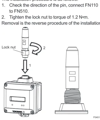
Install FN110 to the FN110 terminal of FN510. Before installation, remove the unscrewed cap attached to the connector and remove the battery pack from FN510.
The installation procedure is as follows.
1. Check the direction of the pin, connect FN110 to FN510.
2. Tighten the lock nut to torque of 1.2 N•m. Removal is the reverse procedure of the installation.
F0401.ai Lock nut
1 2
Figure 4.1 Installation of FN110 and Sealing of the Connector
• To maintain a good connection between the modules, protect the connector from the corrosive atmosphere by the following treatment.
1. Clean the connection to be protected. 2. Wind the butyl rubber self-bonding tape
around the connection. See the manual of the tape about the winding.
3. To protect the butyl rubber self-bonding tape from the environment such as ultraviolet rays and so on, wind vinyl tape (or a vinyl type self-bonding tape) on it. 4. When the tape is necessary, prepare
appropriate tape for the installing environment.
Do not cover the nameplate by the tapes. • When a remote antenna cable is used for
installing FN110, refer to subsection 5.3 “Installation and Connection of FN110”. • Remove the battery pack before installing
FN110. Refer to subsection 8.3 “Replacing the Battery Pack” for the battery pack removing.
• When installing FN110, fix the FN110 by tightening the lock nut. Screwing by holding the FN110 housing may cause failure such as cable disconnection. The same manner should be taken when removing the FN110.
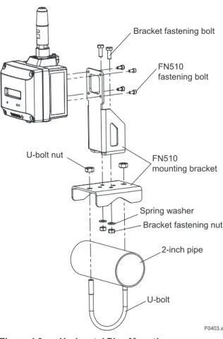
4.2.2 Mounting of FN510
Bracket fastening bolt FN510 fastening bolt
FN510 mounting bracket
U-bolt nut
Spring washer Bracket fastening nut
2-inch pipe
fastening bolt
U-bolt nut
Spring washer Bracket fastening nut
2-inch pipe
U-bolt FN510
mounting bracket
F0403.ai
Figure 4.3 Horizontal Pipe Mounting
To install FN510 on a 50A (2-inch) pipe, follow
the procedure below.
1) Assemble the FN510 mounting bracket. 2) Install FN510 to the mounting bracket using
provided bolt (4) with a torque 1.4 N•m. 3) Install FN510 mounting bracket to the 2-inch
5.1 Notes on Wiring
IMPORTANT
• Apply a waterproofing sealant to the threads of the connection port. (It is recommended that you use non-hardening sealant made of silicon resin for waterproofing.)
• Lay wiring as far away as possible from electrical noise sources such as large transformers, motors and power supplies. • Remove the wiring connection dust-caps
before wiring.
• When you open the front panel, pay great attention to the environmental conditions in order to prevent dust and water droplets entering inside the product.
• To run wiring to the sensor, pay sufficient attention to the wiring parameters described in section 2.6 “Installation of an Explosion Protected Instrument.”
• To prevent electrical noise, the signal cable and the power cable must not be housed in the same conduit.
NOTE
• When wiring where the ambient temperature is high or low, use the cable or wire that appropriate to that place.
• When the maximum operating temperature is more than 60°C, use the cable of 85°C or higher temperature rating.
5.2 Cable Selection
For wiring the sensor and the FN510, use a shielded multi-core cable of AWG22 to 14.
Applicable Cables
Cables for industrial equipment such as; • Control cables: JIS C 3401
Use the following grounding cable.
Applicable Cables
Insulated cables for industrial equipment such as; • 600V polyvinyl chloride insulated wires (IV); JIS
C3307
• Polyvinyl chloride insulated wires for electrical apparatus (KIV); JIS C3316
• 600V grade heat-resistant polyvinyl chloride insulated wires (HIV); JIS C3317
• Heatproof vinyl insulated wires VW-1 (UL1015/ UL1007) Wire size
• Core: AWG14 to 13 (2mm2 to 2.6mm2)
Termination
• Use a ring tongue terminal for M4 terminals: with an insulation sleeve
The FN110 terminal is covered with a cap at the time of deliverty. Keep the cap attached until connecting the FN110 or remote antenna cable to protect the inside connection part. The unscrewed cap should be stored in order to replace it immediately after the FN110 or remote antenna cable is removed. If there is a possibility that get wet with water, order FN510 with optional specification for a protection cap.
5.3.1 Installation of FN110
Location of FN110
Mount the FN110 at the proper location according to the wireless environment described in subsection 2.4 “Selecting the Installation Location”. The mounting to the pipe such as 50A (2-inch) pipe needs to secure the enough strength to endure a strong wind, vibration and so on. The FN110 must be mounted vertically.
Fixing of FN110
Fix the FN110 on a 50A (2-inch) pipe with the mounting bracket provided as the remote antenna cable option.
2) Connect the remote antenna cable to the FN110.
3) Protect the connection as necessary. For details of the protection, refer to subsection 4.2.1 “Installation of FN110”.
4) Fix the FN110 to the mounting bracket.
FN110 holder FN110 mounting bracket FN110 holder bolt U-bolt Bracket fastening nut Bracket fastening bolt Spring washer U-bolt nut FN110 Remote antenna cable 2-inch pipe mounting bracket 2-inch pipe F0501.ai
Figure 5.1 Horizontal Pipe Mounting of FN110
2-inch pipe Bracketfastening nut Spring washer
U-bolt nut FN110
mounting bracket FN110 holder bolt
FN110
Remote antenna cable
FN110 holder Bracket fastening bolt 2-inch pipe mounting bracket U-bolt F0502.ai
follow the procedure below.
Remove the battery pack from FN510 before connecting the remote antenna cable.
1. Connect the FN110 and the FN510 with the dedicated remote antenna cable. Tighten the connector of the remote antenna cable with a torque of 1 to 1.2 N•m. The minimum bending radius should be more than 100 mm.
2. Protect the connectors of the FN110 and remote antenna cable as necessary. For details of the protection, refer to subsection 4.2.1 “Installation of FN110”.
3. Fix the remote antenna cable to an appropriate structure to protect the cable from the vibration, wind, and so on. The minimum bending radius for fi xing in the state maintained for a long period should be more than 100 mm.
F0503.ai
Figure 5.3 Sealing of the Remote Antenna Cable
CAUTION
• Use the dedicated remote antenna cable provided by Yokogawa as accessories for FN110.
• The remote antenna cable and other cables should not be bundled together.
• Remove the battery pack before installing FN110. Refer to subsection 8.3 “Replacing the Battery Pack” for the battery pack
Strip the insulated cover of the cable end.
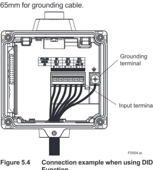
5.4.1 Connecting Input Terminal and Grounding Terminal
Vertical Connection
After stripping the insulated cover, keep a length of about 50mm for input signal cables, and about 65mm for grounding cable.
F0504.ai
Grounding terminal
Input terminal
Figure 5.4 Connection example when using DIDO Function
The cable gland is not included. Prepare a cable gland with a fl at gasket matching the electrical connection.
When M20 female is selected for vertical connection, tighten the cable gland with a torque of 2 N•m. When G 1/2 female or 1/2 NPT female is selected for vertical connection, fi x the hexagonal shape part by tool and tighten the cable gland as shown in Figure 5.5.
F0505.ai
gland. (It is recommended that you use non-hardening sealant made of silicon resin for waterproofing.)
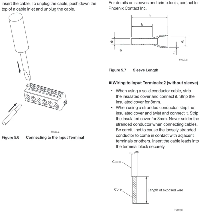
Input Terminal
Input terminal is a spring terminal. When using a solid conductor cable or with sleeve, connect the cable to the input terminal. When using a standard conductor, push down the top of a cable inlet and insert the cable. To unplug the cable, push down the top of a cable inlet and unplug the cable.
F0506.ai
Figure 5.6 Connecting to the Input Terminal
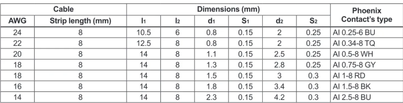
does not match the length of sleeve (l2), strip the
cable to the correct length. Strip the cable for a length so that the core wire slightly extends from the metal tube of the sleeve. If this causes the length of the metal tube of the sleeve to be slightly shorter than the stripping length, this is no problem. The wiring cables and applicable sleeves are listed in the table below. Use the same manufacturer for sleeves and tools.
Example of tool: Phoenix Contact’s CRIMPFOX6 For details on sleeves and crimp tools, contact to Phoenix Contact Inc.
l1 l2 d1 s1 s2 d2 F0507.ai
Figure 5.7 Sleeve Length
Wiring to Input Terminals:2 (without sleeve)
• When using a solid conductor cable, strip the insulated cover and connect it. Strip the insulated cover for 8mm.
• When using a stranded conductor, strip the insulated cover and twist and connect it. Strip the insulated cover for 8mm. Never solder the stranded conductor when connecting cables. Be careful not to cause the loosely stranded conductor to come in contact with adjacent terminals or others. Insert the cable leads into the terminal block securely.
Cable
Core Length of exposed wire
F0508.ai
24 8 10.5 6 0.8 0.15 2 0.25 AI 0.25-6 BU 22 8 12.5 8 0.8 0.15 2 0.25 AI 0.34-8 TQ 20 8 14 8 1.1 0.15 2.5 0.25 AI 0.5-8 WH 18 8 14 8 1.3 0.15 2.8 0.25 AI 0.75-8 GY 18 8 14 8 1.5 0.15 3 0.3 AI 1-8 RD 16 8 14 8 1.8 0.15 3.4 0.3 AI 1.5-8 BK 14 8 14 8 2.3 0.15 4.2 0.3 AI 2.5-8 BU
Connect external device as Figure 5.9.
Input Wiring AI F0509.ai 1 2 3 4 5 6 + -+ -4-20mA Analog Device
* A power supply to the 4-20 mA Analog Device is necessary. DIDO F0510.ai 1 2 3 4 5 6 + - + - + -+ -Dry contact External Power Source Load PULSE 1 2 3 4 5 6 +
-Dry contact F0511.ai
Figure 5.9 Input Terminal Wire Connection Diagram
IMPORTANT
• Do not apply external voltage to the DI, DO and PULSE terminals.
• The DO output is an open drain output. Ensure that the applied current or voltage to the DO terminals is within the specification range.
CAUTION
• Remove the battery pack before wiring. Refer to subsection 8.3 “Replacing the Battery Pack” for the battery pack removing. • Connect the devices to the correct terminals.
Operating with incorrect connection may cause damage to FN510 or connected devices.
NOTE
Strip the insulated cover of the input cable inside the FN510 so as not to interfere with the battery pack.
Wiring to Ground Terminal
Protect the cable of the ground terminal by using heat-shrink tubing, etc. Use a ring tongue terminal for M4 terminals with an insulation sleeve.
terminal on the top of the housing.
Do not share the ground wiring with other devices.
Ground Wiring
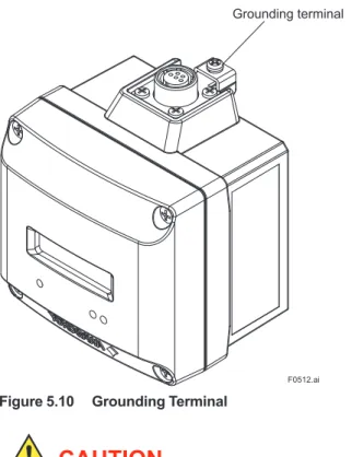
Connect the grounding cable to ground terminal on the top of the housing.
Grounding terminal
F0512.ai
Figure 5.10 Grounding Terminal
CAUTION
Grounding is required for safe operation.
Input Cable Wiring
The input cable shield should be connected to grounding terminal inside of the housing.
• The input cable shield should not be connected to grounding terminal inside of the connected sensor.
• Connection to the ground terminal of the connected device housing, refer to the User's Manual.
6.1 Preparation for Starting
Operation
NOTE
• Before using FN510, connect FN110. For detail on how to install the FN110, refer to subsection 4.2.1 “Installation of FN110”. • It is required to set security and network information to enable this product to be connected to the field wireless network. For more details, refer to subsection 6.3 “Connecting to the Field Wireless Network”.
(1) Checking Installation and Wiring
Ensure that the FN510, FN110 and the connected device are installed correctly according to the procedures described in section 4 “Installation”, and section 5 “Wiring”.
(2) Power On and Connecting to the Field Wireless Network
Insert batteries into the battery case, and install to the FN510. For details of installation of battery, refer to subsection 8.3 “Replacing the Battery Pack” and subsection 8.4 “Replacing the Batteries”. Provisioning is to set the security and network information. For details of provisioning, refer to section 6.3 “Connecting to the Field Wireless Network”.
(3) Checking the parameter of the FN510
Use the device configuration tool and confirm that the connected device and the FN510 operate properly. Check parameter values or change the setpoints as necessary.
IMPORTANT
Use the device configuration tool and confirm that the Sensor Type parameter setting in TRANCEDUCER block matches the input wiring. If the parameter is not properly set, change the parameter to match the input type. After changing the parameter, FN510 will restart automatically.
The integral indicator can be used to confirm that this product is operating properly. For details on how to confirm this, refer to subsection 7.4
“Self-ISA100 devices display self-diagnostic information in an easy-to-understand manner using four categories (Function check, Maintenance required, Failure, and Out of specification) according to NAMUR NE107*
* NAMUR NE107 “Self-Monitoring and Diagnosis of Field Devices” Confirm operation status by integral indicator
If the FN510 is faulty, an error code is displayed.
F0601.ai
Figure 6.1 Integral Indicator with Error Code
NOTE
If any of the above errors are indicated on the display of the integral indicator or the device configuration tool, refer to subsection 8.10.3 “Errors and Countermeasures” for the corrective action.
Verify and Change the FN510 Setting and Values
The followings are the required settings of the FN510. These parameters must be set before starting operation.
• TRANSDUCER block:Sensor Type
Select from DIDO, DI Pulse Count, 4-20 mA or “Not Used” the type of the device to be connected to FN510. Connect the device to the proper terminals of FN510 depending on the selection.
Select “Not Used” when using as a routing device without the connected device.
6.2 Starting Operation
Ensure that the installation, the wiring, the network connection, and the behavior of the FN510 are correct before starting operation.
IMPORTANT
Close the front panel. Tighten each screws to a torque of 0.7 N•m.
Field Wireless Network
FN510 does not need to be connected with a physical wire. Instead of physical wiring, to set security and field network information is required. This procedure is called a provisioning.
FN510 supports provisioning via infrared communication using a provisioning device and can be securely connected to a network. If the provisioning information is not set, the FN510 cannot be connected to the field wireless network.
NOTE
Before provisioning, connect the FN110. For detail on how to install the FN110, refer to subsection 4.2.1 “Installation of FN110”. For details on provisioning using a provisioning device, connecting to a field wireless network and the setting procedure, refer to the User’s Manual, FieldMate Versatile Device Management Wizard (IM 01R01A01-01E), YFGW710 Field Wireless Integrated Gateway (IM 01W01F01-01EN), and YFGW410 Field Wireless Management Station (IM 01W02D01-01EN).
F0602.ai Within 30cm
Figure 6.2 Provisioning Example
field wireless device using FieldMate and an infrared adapter.
When using the Yokogawa recommended near infrared adapter for the provisioning device, the distance between the front panel of this product and the infrared surface of the near infrared adapter should be within 30 cm. For details on the Yokogawa recommended infrared adapter, refer to subsection 8.2 “Recommended Products List”. Perform the following provisioning tasks.
• Setting provisioning information • Creating a provisioning information file
(1) Setting provisioning information
Set the device tag and Network ID using a FieldMate provisioning function. The device tag, Network ID, and join key are set in the field wireless device. It is not necessary to input a join key because FieldMate automatically generates it.
• Setting device tag
The device tag is used for the user to recognize the field wireless device.
• Setting Network ID
This is the Network ID for the field wireless network to which the field wireless device is connected. Set a value from 2 to 65535. The field wireless device is connected to the field wireless network corresponding to the Network ID set by provisioning work.
(2) Creating a provisioning information file
The following provisioned information is stored in the provisioning information file.
• Network ID • Device tag • EUI64 • Join key
• Provisioner (name of the user who performed provisioning work by Field Mate)
• Date (Time and date when provisioning was performed by FieldMate)
This provisioning information file is required to load from the field wireless configurator to the field wireless integrated gateway. Store the file carefully.
F0605.ai
Figure 6.5 Display showing Ready and Pause State
(c) Confirm Connecting Status
F0606.ai
Figure 6.6 Display showing Confirm Connecting Status State
(d) Join
F0607.ai
Figure 6.7 Display showing Join State
NOTE
If the FN510 searches the field wireless network for long time low ambient temperature condition, sometimes error “AL.20 LOWBAT” is displayed on the integral indicator. It occurs because of battery characteristics even when using new batteries. After joining to the field wireless network, this error will be cleared within one hour if battery has no failure.
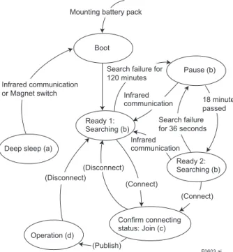
Mounting the battery pack automatically starts a search for the field wireless network and the device goes into the join state when the field wireless gateway is found. If the field wireless gateway is not found and a specified time based on the silence mode has elapsed, a cycle of 18-minute pause and 36-second search is repeated until the device can join the field wireless network.
For details on the silence setting, refer to subsection 7.3.10 “Switching to the Silence Mode”.
F0603.ai
Mounting battery pack
Boot Pause (b) Infrared communication Ready 2: Searching (b) (Connect) (Connect) Confirm connecting status: Join (c) (Publish) Operation (d) (Disconnect) (Disconnect) Ready 1: Searching (b)
Deep sleep (a) Infrared communication Infrared communication
or Magnet switch
Search failure for 120 minutes
Search failure for 36 seconds
18 minutes passed
* By using a magnet switch or field device configuration tool, transitions to the Deep sleep state from any state.
Figure 6.3 Wireless Status Transition (a) Deep Sleep
F0604.ai
Figure 6.4 Display showing Deep Sleep State Displays for 2 seconds in deep sleep setting, and then turns off.
F0610.ai
Figure 6.10 Display after Power On
Setting the Find Device
When UAPMO.Find Device is set from FieldMate or PRM, following is displayed. The duration the display can be changed. For detail on how to display, refer to section 7 “Setting Parameters”.
F0611.ai
Figure 6.11 Display when Find Device is set
6.5 Shutting Down
When shut down the FN510, remove the battery pack or set the FN510 to deep sleep mode by the device configuration tool or magnet switch.
NOTE
• Refer to subsection 8.3 “Replacing the Battery Pack” for the battery pack removing. • When storing the FN510 with a battery
pack inserted, it is recommended to put the FN510 into deep sleep mode to conserve battery power. For details on how to switch to deep sleep mode, refer to subsection 7.3.9 “Switching to the Deep Sleep Mode”. When the write protection is enabled, the lock
icon is displayed in the upper left corner of the integral indicator. For details on how to enable write protection, refer to subsection 7.3.8 “Write Protect”.
Wireless Communication Status
The status of wireless communication is indicated by the segments on the top of the integral indicator. Possible status are shown in Table 6.1.
Table 6.1 Wireless Communication Status List Integral Indicator Wireless Communication Status
No display • RePause (Silence
mode) • ReOperation (Published) • Ready • Joining • Confirm connecting status • Startup • Alert Process Value
The process value obtained from the sensor is displayed. For detail information about the display settings, refer to section 7 “Setting Parameters”. When sensor data is more than five orders of magnitude, scroll automatically after 2 seconds.
F0608.ai
Figure 6.8 Example of Data Scrolling
When publish is not configured, following is displayed.
F0609.ai
FN510 can remotely handle sensor type changes, Tag No. setup, monitoring of self-diagnostic results, according to communication with the fi eld wireless confi guration tool or the device confi guration tool.
7.1 Preparation for Parameter
Setting
This product can be set parameters via infrared port or fi eld wireless network.
When setting parameters via fi eld wireless network, connect this product to the fi eld wireless network. For details on how to connect to the fi eld wireless network, refer to subsection 6.3 “Connecting to the Field Wireless Network”.
When setting parameters via infrared port, use the infrared port on front of this product.
Infrared port
F0701.ai
Figure 7.1 Connecting the Confi guration Tool
7.2 Preparing Software
7.2.1 Softwares for the Field Wireless Confi guration Tool and the Device Confi guration Tool
Before using the device confi guration tool, confi rm that CF/DD and DeviceDTM for this product are installed in the device confi guration tool.
Refer to the following website for the latest information on CF/DD and DeviceDTM. <http://www.fi eld-wireless.com/>
CF(Capabilities File)/DD(Device Description)
A CF fi le contains information, such as the vendor of the fi eld device, its model and revision, available types of process data (fl ow rate, temperature, pressure, etc.), and number of data items. A DD fi le contains the information on parameters, such as data structures and attributes.
DeviceDTM
DeviceDTM, (Device Type Manager) is driver software for fi eld devices provided based on the FDT (Field Device Tool) technology.
The fi eld wireless confi guration tool or the device confi guration tool allows to read the device information.
Refer to subsection 8.2 “Recommended Products List” for the fi eld wireless confi guration tool or the device confi guration tool of our recommendation. Refer to the following website for the latest confi guration tool and DeviceFile.
<http://www.fi eld-wireless.com/>
7.2.2 Software Download
Software download function allows to update wireless fi eld device software via ISA100.11a wireless communication. For details, refer to YFGW710 Field Wireless Integrated Gateway (IM 01W01F01-01EN) or YFGW410 Field Wireless Management Station (IM 01W02D01-01EN).
table for a summary of how and when each parameter is used.
IMPORTANT
After setting and sending data with the field wireless configuration tool or the device configuration tool, wait 30 seconds before turning off the FN510. If it is turned off too soon, the setting will not be stored in the FN510. Table 7.1 Parameter Usage and Selection
Item Description
Tag No. Sets the Tag No. for Device Tag (software tag). The Tag No. can be set sixteen characters (alphanumeric characters, including – ).
Output mode Allows outputting process value and self-diagnostic information via field wireless network.
Either or all of sensor value (AI1 block: Process Value, BI1/BI2 block: Process Value Binary, BO1 block: Read Back Value Binary), and self-diagnostic information (UAPMO block: Diagnostic Status) can be set output data.
Input mode Allows inputting process value via field wireless network.
Sensor value (BO1:Output Value Binary) can be set as input data. Integral indicator display setting Sets the process value to display on the LCD.
Software write protect Prohibit writing the setting data.
Memo field Memo field available to write the check date, checker and others (as an adjustment information), or anything.
Operational mode Set the operational mode of the sensor and integral indicator, etc.
NOTE
Some of the parameter setting are in the dialogue form called method, by following the on-line instructions you can configure the parameters easily.
The function of FN310 is shown below. Some functions may not be available depending on the device configuration tool used. When the device configuration tool of our recommendation is used, the software attached to the Field Wireless Integrated Gateway or Field Wireless Management Station is necessary for setting the dotted line part. Refer to subsection 8.2 “Recommended Products List” for the field wireless configuration tool of our
recommendation.
• Other Faults Alert • Faults Non-Compliance Alert • Faults Process Influence Alert • Simulation Active Alert • Soft Update Incomplete Alert • Power Low Alert • Power Critical Low Alert • Fault Prediction Alert • Environmental Conditions Alert • Outside Sensor Limits Alert • Out of Service Alert • Calibration Problem Alert • Faults Sensor or Actuator Alert • Faults Electronics Alert • Version Revision
• CTS Version • ITS Version • Identification Number
• Set Find Device • Antenna Temperature • Adapter Temperature • Temperature Unit
• APP Download • DESCRIPTION • STATE • MAX_BLOCK_SIZE • LAST_BLOCK_DOWNLOADED • ERROR_CODE • COMM_ENDPOINT • COMM_CONTRACT • PUB_ITEM_MAX • PUB_ITEM_NUM • PUB_ITEM
• Network address of remote endpoint • Transport layer port at remote endpoint • Object ID at remote endpoint • Stale data limit
• Data publication period • Ideal publication phase • Publish Auto Retransmit • Configuration status • Contract ID • Contract Status • Actual Phase • Object ID • Attribute ID • Attribute Index • Size • Configuration
• Others • COMM_ENDPOINT• SUB_ITEM_MAX • SUB_ITEM_NUM • SUB_ITEM
• Network address of remote endpoint • Transport layer port at remote endpoint • Object ID at remote endpoint • Stale data limit
• Data publication period • Ideal publication phase • Publish Auto Retransmit • Configuration status • Object ID • Attribute ID • Attribute Index • Size Menu (Online) • UAPMO • UDO • CO • TRANSDUCER • AI1 • BI1 • BI2 • BO1 • UAPMO • UDO • CO • TRANSDUCER • AI1 • BI1 • BI2 • BO1 (UAPMO) • Configuration • Diagnostics • Alerts • Power Status • Identification • Others (Configuration) • UAP Option • Hardware Write Protect • Static Revision • Reset Energy Left • Energy Harvest Type (Diagnostics) • Diagnostic Status • Diagnostic Status Detail1 • Diagnostic Status Detail2 • Diagnostic Switch • Diagnostic Configuration
(Power Status) • Energy Left • Power Supply Status • Power Supply Voltage (Identification) (Others) (APP Download) (UDO) (CO) • Configuration • Others (Configuration) (COMM_ENDPOINT) (COMM_CONTRACT) (PUB_ITEM) (Others) (COMM_ENDPOINT) (Configuration) (SUB_ITEM) (DIS) • REVISION (Alerts)
• Tag Description • Block Info • Block Mode • Dynamic Variables • Configuration • Simulate Switch • Simulate Value • Block Info • Block Mode • Dynamic Variables • Configuration • Discrete Value.Status • Discrete Value.Value • Tag Description • Block Info • Block Mode • Dynamic Variables • Configuration • Block Mode • Concentrator OID • Options • Fault State Time • Fault State Value • Sensor Serial • Mode.Target • Mode.Actual • Mode.Permitted • Mode.Normal . • Special Cmd
• Change Sensor Type
F0703.ai (AI1) (BI1/BI2) (BO1) (Configuration) (Block Mode) • Discrete Value.Status • Discrete Value.Value
(Process Value Binary/ReadBack Value Binary) • Mode.Target
• Mode.Actual • Mode.Permitted • Mode.Normal
(Block Mode)
(Simulate Value Binary)
• Process Value Binary • ReadBack Value Binary (Dynamic Variables) • Mode.Target • Mode.Actual • Mode.Permitted • Mode.Normal (Block Mode) (Block Info) • Block Mode • Concentrator OID • Options • Sensor Serial (Configuration) • Discrete Value.Status • Discrete Value.Value
(Process Value Binary) (Dynamic Variables)
• Process Value Binary • Simulation • Mode.Target • Mode.Actual • Mode.Permitted • Mode.Normal (Block Mode) • Tag Description (Block Info) • Sensor Range.EU at 100% • Sensor Range.EU at 0% • Sensor Range.Units Index • Sensor Range.Decimal (Sensor Range) (Scale) • Scale.EU at 100% * • Scale.EU at 0% * • Scale.Units Index * • Scale.Decimal * • Mode.Target • Mode.Actual • Mode.Permitted • Mode.Normal (Block Mode) (Configuration) • Block Mode • Concentrator OID • Scale * • Sensor Range • Sensor Serial • Reset Pulse Count • PV Energy Left Enable
• Simulate Value.Status • Simulate Value.Value (Simulate Value) • Process Value.Status • Process Value.Value (Process Value) (Dynamic Variables) • Process Value • Simulation • Mode.Target • Mode.Actual • Mode.Permitted • Mode.Normal (Block Mode) (Block Info) (Others) • Wireless Status • Display Selection • LCD Intermittent Time • LCD Exp Mode • Measurement Rate • Sensor Type (Simulation) (Simulation) • Simulate Switch • Simulate Value Binary
• UAPMO • TRANSDUCER • AI1 • BI1 • BI2 • BO1 Online Menu • Device Configuration • Diagnostics • Process Variable
(Device Configuration) (UAPMO) (Configuration/Setup)
(Identification)
(Alerts)
• Set Find Device • Antenna Temperature • Adapter Temperature • Temperature Unit (Others) • Configuration/Setup (TRANSDUCER) • Tag Description (Block Info) • Special Cmd • Change Sensor Type (Others)
• Tag Description (Block Mode)
(Configuration) (Block Mode)
(Scale)
(Sensor Range)
F0704.ai
• Configuration/Setup • UAP Option • Hardware Write Protect • Static Revision • Reset Energy Left • Energy Harvest Type • Version Revision • CTS Version • ITS Version • Identification Number • Other Faults Alert • Faults Non-Compliance Alert • Faults Process Influence Alert • Simulation Active Alert • Soft Update Incomplete Alert • Power Low Alert • Power Critical Low Alert • Fault Prediction Alert • Environmental Conditions Alert • Outside Sensor Limits Alert • Out of Service Alert • Calibration Problem Alert • Faults Sensor or Actuator Alert • Faults Electronics Alert
(Configuration/Calibration) • Model • Serial Number • Wireless Status • Display Selection • LCD Intermittent Time • LCD Exp Mode • Measurement Rate • Sensor Type (Block Info) (AI1) • Configuration/Setup • Mode.Target • Mode.Actual • Mode.Permitted • Mode.Normal • Block Mode • Concentrator OID • Scale * • Sensor Range • Sensor Serial • Reset Pulse Count • PV Energy Left Enable
• Mode.Target • Mode.Actual • Mode.Permitted • Mode.Normal • Scale.EU at 100% * • Scale.EU at 0% * • Scale.Units Index * • Scale.Decimal * • Sensor Range.EU at 100% • Sensor Range.EU at 0% • Sensor Range.Units Index • Sensor Range.Decimal
(Configuration) (Block Mode)
• Configuration/Setup • Tag Description (Block Info) (Block Mode) (Configuration) (Block Mode) • UAPMO (Diagnostic) • Device Diagnostics (UAPMO) (Diagnostics) (Power Status) (Process Variable) • Process Variable
(Dynamic Variables) (Process Value)
(Simulation) (Simulate Value)
• Process Variable
(Dynamic Variables) (Process Value Binary)
(Simulation) (Simulate Value Binary)
• Process Variable
(BO1) (Dynamic Variables)
F0705.ai (BO1) • Mode.Permitted • Mode.Normal • Block Mode • Concentrator OID • Options • Sensor Serial • Mode.Target • Mode.Actual • Mode.Permitted • Mode.Normal • Block Mode • Concentrator OID • Options • Fault State Time • Fault State Value • Sensor Serial • Mode.Target • Mode.Actual • Mode.Permitted • Mode.Normal • Mode.Target • Mode.Actual • Mode.Permitted • Mode.Normal • Diagnostic Status • Diagnostic Status Detail1 • Diagnostic Status Detail2 • Diagnostic Switch • Diagnostic Configuration • Energy Left • Power Supply Status • Power Supply Voltage
• AI1 • BI1 • BI2 • BO1 (AI1) • Process Value
• Simulation • Process Value.Status• Process Value.Value • Simulate Switch
• Simulate Value • Simulate Value.Status• Simulate Value.Value (BI1/BI2)
• Process Value Binary
• Simulation • Discrete Value.Status• Discrete Value.Value • Simulate Switch
• Simulate Value Binary • Discrete Value.Status• Discrete Value.Value • Output Value Binary
• ReadBack Value Binary
(Output Value Binary/ReadBack Value Binary) • Discrete Value.Status
• Discrete Value.Value
(1) Network Information
CO block: Configuration
The network-related information can be checked. DIS block: Configuration
Information related to the communication handled by DO can be checked.
(2) Update Time
CO block: Data publication period DIS block: Data publication period
For AI, DI Pulse Count, and DI, set the update time value to the data publication period in the CO block within the range of 1 to 3600 seconds. For DO, set the update time value to the data publication period in the DIS block within the range of 2 to 3600 seconds.
NOTE
If you want to use DI and DO together, the update time value of DI should be set to 2 seconds or more.
The setting affects the battery life.
When update time is set 0 second, FN510 stops updating process variables via the field wireless network. And it also stops the acquisition of process variables from the connected device.
(3) Remaining Battery Life
UAPMO block: Energy Left
The number of days of battery life remaining is indicated assuming ambient temperature condition as 23 °C. It takes several days for the value to be stabilized after the power on and initialization of the remaining battery life.
UAPMO block: Reset Energy Left
When changing batteries, the remaining battery life is initialized by Reset Energy Left parameter.
(4) LCD Display
TRANSDUCER block: LCD Intermittent Time The integral indicator has three modes: Continuous, Intermittent, and Off. These modes are switched by LCD Intermittent Time parameter. The intermittent mode repeats on/off at defined seconds.
In any mode, current process value is displayed by magnet switch operation. After displaying current process value, returns to the configured mode. Refer to subsection 8.6 “Switching LCD Display” for
AL.03 error, the LCD display does not dim regardless of the status in LCD mode. See Table 8.4 for details.
7.3.4 Tag and Device Information
You can specify the Device Tag when ordering the corresponding FN110 Field Wireless Communication Module.
Device Tag and device information can be checked as follows.
Procedure to Read the Device Tag and Device Information
• Device Tag (Software Tag)
This is specified by writing characters (up to 16 characters) that differs from those specified in Tag No. to the module. For details how to confirm this, refer to subsection “Connecting to the Field Wireless Network”.
• Tag Description
This is a universal parameter to store the comment that describes the content of the tag located in the TRANSDUCER and AI1/BI1/BI2/ BO1 blocks.
Limitation of Device Information
When changing the device information, input the information based on the following limitation on the number of characters.
• Message function (up to 32 characters) TRANSDUCER block: Tag Description AI1/BI1/BI2/BO1 block: Tag Description
7.3.5 Setup the Integral Indicator
TRANSDUCER block: LCD Exp Mode
Set the display method of the PV on the integral indicator. Index display or base display is selectable.
7.3.6 Sensor Type
Process values are assigned as shown in the table below depending on the Sensor Type.
Table 7.2 Block Assignment
Sensor Type Assignment to Block
DIDO BI1 block (IN1)
BI2 block (IN2) BO1 block (OUT)
DI Pulse Count AI1 block
4-20mA AI1 block