PROCESSING AND MICROSTRUCTURE EFFECTS ON THE STRENGTH AND THE LOCALIZED CORROSION RESISTANCE OF ULTRA-FINE GRAINED Al-Mg-Si ALLOYS
A Dissertation by RAMATOU LY
Submitted to the Office of Graduate and Professional Studies of Texas A&M University
in partial fulfillment of the requirements for the degree of DOCTOR OF PHILOSOPHY
Chair of Committee, Homero Castaneda-Lopez Co-Chair of Committee, Karl. T. Hartwig
Committee Members, Ankit Srivastava Hong Liang Head of Department, Ibrahim Karaman
December 2019
Major Subject: Materials Science and Engineering
ii ABSTRACT
Improving the strength, and the corrosion resistance of aluminum alloys simultaneously through aging treatment, and grain refinement is a challenge as these two properties are mutually exclusive. In this work, we investigated the effects of shear banding, dynamic recrystallization, and precipitation on the corrosion susceptibility, and the strength of an ultra-fine grained (UFG) AA6061 aluminum alloy. For that, we extruded the material by equal channel angular pressing (ECAP) up to seven passes following route Bc combined with a post-aging treatment at 100 ⸰C. We first characterized the microstructure after processing in depth before investigating corrosion susceptibility by accelerated immersion tests, and electrochemical testing. We found that after 3 ECAP passes, the AlFeSi intermetallic compounds are fragmented and closely spaced along the shear direction and within the shear planes of the material making this direction and plane highly susceptible to pitting. Besides, the shear bands are preferred regions for precipitation after post-aging treatment. Therefore the corrosion susceptibility of UFG AA6061 alloys is tailored by the shear bands network of the material, and the precipitation within the bands.The immersion and electrochemical tests reveal that filiform corrosion, and intergranular corrosion (IGC) are severe when the material is partially recrystallized and peak aged. Also, the bulk potentiodynamic response is significantly affected by the bulk composition, and the precipitation within the shear bands. In addition, passivation is easier after ECAP regardless of the post-aging treatment. However the passive film is less stable. We also found that dynamic recrystallization decreases the susceptibility to IGC even at peak aging by reducing the volume fraction and the length of the shear bands. Thus in UFG AA6061 aluminum alloys, the energy stored in the grains seems to influence the susceptibility to IGC more than grain boundary precipitation.
iii DEDICATION
To my parents, my family, and all my friends from Cote d'Ivoire, France, Senegal, Mali, and the United States who have always motivated me, encouraged me, and extended all the help and the support I needed to succeed in this journey.
iv
ACKNOWLEDGEMENTS
I would like to thank my advisor Dr. Homero Castaneda, and my co-advisor Dr. Karl Hartwig for their guidance, and support throughout my Ph.D. My thanks also go to my committee members, Dr. Ankit Srivastava, Dr. Bruce Tai, and Dr. Hong Liang for their interests in my research. Thank you to Dr. Xinghang Zhang for advising me before moving to Purdue University. I am grateful to all the professors and staffs who helped me in my research, and my studies. Thank you to Robert Barber, and Michael Elverud for their technical assistance in performing the ECAP. Thank you to Murat Kaynak, and Dharmesh Patel for their help, time and sympathy. Thanks also go to Dr. Stanislav Verkhoturov for assisting me with the SIMS, Dr. Chun Hsin Kuo for helping me with the SEM, and Dr. Wilson Serem for his guidance with the AFM. I am thankful to Dr. Ahmad Ivan Karayan for his advice, and contributions to the work presented. Many thanks to Yenny Cubides for helping me with the drawings, Wahaz Nasim for his assistance during the EBSD analysis, and Abhinav Srivastava for guiding me during the mechanical testing.
Thank you to Dr. Indranhil Roy, and Dr. Agathe Robisson, for their dedication, and unconditional support when I started my Ph.D. journey at Texas A&M.
Thanks also go to my friends Shuang Quin, Parvin Karimi, Lin Chen, Yash Parikh, Hanna Hlushko, Chin-Hua Cheng, Taymaz Jozaghi and the whole corrosion group for making my time at Texas A&M University a great, and unforgettable experience.
v
CONTRIBUTORS AND FUNDING SOURCES
This work was initially supported by SCHLUMBERGER. The ECAP processing and the mechanical testing were supervised by Dr. Karl T. Hartwig, co-advisor - emeritus professor in the Department of Materials Science & Engineering of Texas A&M. The corrosion testing were supervised by Dr. Homero Castaneda, advisor-Assistant professor in the Department of Materials Science & Engineering of Texas A&M - Director of the national corrosion & materials reliability lab.
Sections 3, 4, and 5 were supervised by Dr. Karl T. Hartwig, Dr. Homero Castaneda, Dr. Ankit Srivastava, Dr. Hong Liang and Dr. Ivan Ahmad Karayan, post-doc fellow in the Department of Materials Science & Engineering of Texas A&M. These sections were published in 2018 and 2019 in three articles listed in the biographical sketch.
vi
SPD Severe Plastic Deformation
ARB Accumulating Roll Bonding
HPT High Pressure Torsion
ECAP Equal Channel Angular Processing
UFG Ultra-Fine Grained
GB Grain Boundary
IGC Intergranular Corrosion
IMC Intermetallic Compounds
HAGBs High Angle Boundaries
LAGBs Low Angle Boundaries
SCE Saturated Calomel Electrodes
EBSD Electron Backscatter Diffraction SEM Scanning Electron Microscope TEM Transmission Electron Microscope
HRTEM High Resolution Transmission Electron Microscope
OM Optical Microscope
VPD Volta Potential Difference
TOF-SIMS Time of Flight Secondary Ions Mass Spectrometry
AFM Atomic Force Microscopy
SKPFM Scanning Kelvin Probe Force Microscopy
vii
Ecorr Corrosion potential
Epit Pitting potential
Erep Repassivation potential
OCP Open Circuit Potential
CPP Cyclic Potentiodynamic Polarization
Rp Polarization Resistance
XRD X-Ray diffraction
3D-APT 3D Atom Probe Tomography
viii
Page
ABSTRACT ... ii
DEDICATION ... iii
ACKNOWLEDGEMENTS ... iv
CONTRIBUTORS AND FUNDING SOURCES ... v
NOMENCLATURE ... vi
TABLE OF CONTENTS ... viii
LIST OF FIGURES ... xi
LIST OF TABLES ... xvi
1. INTRODUCTION ... 1
1.1 Background ... 1
1.2 Technical Approach ... 2
1.3 Dissertation Outline ... 3
2. LITTERATURE REVIEW ... 4
2.1 Aluminum and Aluminum Alloys ... 4
2.1.1 Al-Mg-Si Alloys - The 6xxx Aluminum Series ... 5
2.1.2 Aluminum Alloys... 6
2.2 Accumulative Roll Bonding ... 7
2.3 High Pressure Torsion... 8
2.4 Equal Channel Angular Pressing ... 9
2.4.1 Dynamic Recrystallization and Shear Banding ... 10
2.4.2 Dislocation Density, Grain Size, Grain Boundary Characteristics .. 11
2.4.3 Influence of Hydrostatic Pressure ... 13
2.5 Ultra-Fine Grained Aluminum Alloys 6xxx ... 14
2.5.1 Dynamic Precipitation ... 14
2.5.2 Influence of Aging Treatment ... 15
2.5.3 Fragmentation of Precipitates and Particles ... 16
2.6 Corrosion Mechanisms in Aluminum Alloys ... 17
ix
2.6.2 Pitting and Passivation Breakdown ... 17
2.6.3 Influence of Alloying Elements ... 19
2.6.4 Intergranular Corrosion ... 20
2.7 Corrosion Susceptibility of Ultra-Fine Grained Aluminum Alloys ... 20
2.7.1 Effects of SPD on Grain Size... 20
2.7.2 Effects of SPD on Passivity ... 23
2.7.3 Effects of ECAP on Pitting Corrosion ... 24
2.7.4 Effects of Grain Boundary Misorientation ... 24
2.7.5 Effects of Grain Stored Energy ... 25
2.7.6 Effects of Residual Stress and Strain Localization ... 26
2.8 Application of Ultra-Fine Grained Aluminum Alloys ... 27
3. EFFECTS OF STRAIN LOCALIZATION ON THE CORROSION BEHAVIOR OF ULTRA-FINE GRAINED ALUMINUM ALLOY AA6061 ... 28
3.1 Introduction ... 28
3.2 Experimental Procedure ... 30
3.2.1 Materials and Processing ... 30
3.2.2 Vickers Hardness ... 31
3.2.3 Microstructure Analyses ... 31
3.2.4 Corrosion Immersion Tests ... 32
3.3 Results and Discussion ... 33
3.3.1 Material Microstructure ... 33
3.3.2 Vickers Hardness ... 35
3.3.3 Shear Bands Microstructure ... 36
3.3.4 Volta Potential Distribution ... 41
3.3.5 Immersion Test Results... 43
3.3.6 Shear Bands Corrosion Initiation Mechanism ... 45
3.3.7 IGC Propagation Mechanism ... 47
3.4 Conclusions ... 48
4. INSIGHTS INTO THE ELECTROCHEMICAL RESPONSE OF A PARTIALLY RECRYSTALLIZED AL-Mg-Si ALLOY AND ITS RELATIONSHIP TO CORROSION EVENTS ... 49
4.1 Introduction ... 49
4.2 Experimental Procedure ... 51
4.2.1 Materials and Processing ... 51
4.2.2 Electrochemical Testing ... 52
4.2.3 Microstructure Characterizations ... 52
4.3 Results and Discussion ... 53
4.3.1 Microstructure ... 53
x
4.3.3 Potentiostatic Response and Intergranular Corrosion ... 61
4.3.4 Passivation Behavior ... 64
4.3.5 Sequence of Corrosion Events... 66
4.4 Conclusions ... 69
5. INFLUENCE OF DYNAMIC RECRYSTALLIZATION AND SHEAR BANDING ON THE LOCALIZED CORROSION OF SEVERELY DEFORMED Al-Mg-Si ALLOY... 71
5.1 Introduction ... 71
5.2 Experimental Procedure ... 73
5.2.1 Materials and Processing ... 73
5.2.2 Vickers Hardness ... 74
5.2.3 Microstructure Analysis ... 74
5.2.4 Corrosion Immersion Tests ... 75
5.3 Results and Discussion ... 75
5.3.1 Microstructure Evolution with Processing... 75
5.3.2 Corrosion Immersion Tests ... 81
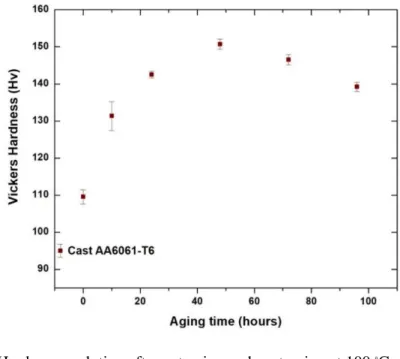
5.4 Conventionally Extruded AA6061 T6 ... 85
5.5 Strength/Corrosion Resistance Relationship... 86
5.6 Practical Application ... 89 5.7 Conclusions ... 89 6. SUMMARY ... 91 6.1 Conclusions ... 91 6.2 Future Work ... 92 REFERENCES ... 93
xi
LIST OF FIGURES
Page
Figure 1 Test matrix ... 2
Figure 2 Aluminum FCC unit cell crystal showing atomic position, closed packed directions <110>, and closed packed plane (111) ... 4
Figure 3 Schematic of T6 heat treatment procedure for aluminum 6XXX alloys ... 6
Figure 4 Principle of accumulate roll bonding (ARB) ... 8
Figure 5 Principle of high pressure torsion (HPT) ... 9
Figure 6 Principle of equal channel angular pressing (ECAP). Illustration of the ECAP routes designations. ... 10
Figure 7 Microstructure and grain boundary misorientation evolution during ECAP ... 11
Figure 8 Schematic of the evolution of grain boundary misorientation in pure aluminum after ECAP following Route Bc ... 12
Figure 9 Modelling of the evolution of average cell size after ECAP with/without the use of backpressure (BP) ... 13
Figure 10 Evolution of dislocation density in the cell interior after ECAP with/without the use of backpressure (BP) ... 14
Figure 11 TEM images of spherical/globular Mg2Si precipitates in an AA6082 alloy (a) After 1 ECAP pass (b) after 6 ECAP passes. ... 15
Figure 12 SEM images showing the effects of the number of ECAP passes following route Bc on the pits morphology of an AlMg alloy after potentiodynamic polarization in 0.1 M NaCl (a) CG state, (b) 4 passes, (c) 8 passes and (d) 12 passes ... 25
Figure 13 (a) Local micro strain distribution in an AlMgSi0.5 alloy after 1 ECAP pass. M = Matrix, SB = Shear Bands. (b) Potentiodynamic polarization curve of the shear bands and the matrix in an aerated 0.1M NaCl solution. ... 26
Figure 14 ECAP 90-degree die and x, y, z plane designations. The crossed region indicates the center part of the bar tested in this study ... 33
xii
Page Figure 15 (a) SEM backscatter image of the As-extruded material showing the AlFeSi
compounds distribution. (b) EDX analysis results confirming the AlFeSi compounds chemistry. (c) Etched microstructure of the As-extruded material
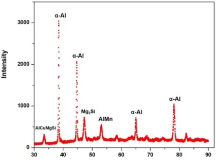
showing shear band structure. (d) Corresponding SEM image ... 34 Figure 16 XRD pattern of the As-extruded material after three ECAP passes indicating the existence of AlCuMgSi and Mg2Si phases in the material ... 35 Figure 17 Vickers Hardness evolution after extrusion and post-aging at 100 ⸰C up to four
days ... 36 Figure 18 TOF-SIMS depth profile images of Fe (top) and AlSi-compounds (bottom) after processing for different sputtering times. (a, d) 5 minutes sputtering, (b, e) 30
minutes sputtering (c, f) 1 hour sputtering ... 37 Figure 19 AFM maps of the material after extrusion and peak aging. (a) Topography map bands showing shear band structure and preferential precipitation inside the shear (b) Topography map of the shear band interior showing precipitate
morphology and distribution. (c) Corresponding phase map with (1) indicating “point” precipitates, (2) indicating “lineal” precipitates and (3) “cluster”
precipitates ... 39 Figure 20 AFM (a) topography map and (b) phase map of the As-extruded material
showing small precipitates homogeneously distributed in the matrix ... 40 Figure 21 EBSD results after three ECAP passes. (a) Inverse pole figure showing shear
band internal structure composed of fine equiaxed grains. (b) Corresponding
grain boundary misorientation with thin black lines indicating LAGB and thin red lines for HAGBs ... 41 Figure 22 (a) VPD map of the Extruded & peak aged material obtained by SKPFM. (b) VPD difference scan of the lineal precipitates. (c) VPD scan of the cluster precipitates. (d) XRD pattern of the surface indicating Mg2Si and AlCuMgSi phases ... 42 Figure 23 Material’s cross-sections after immersion for 24 hours in 30 g NaCl/L & 10 mL HCl/L, pH ~1. (a) As-extruded material. (b) Extruded & peak aged material
two days aging). (c) Extruded & overaged material (three days aging) ... 43 Figure 24 Corrosion morphology of the exposed surfaces after immersion for 24 hours in 30 g NaCl/L and 10 ml of concentrated HCl/L, pH ~1. (a) OM image of the as-extruded material surface showing pitting attack. (b) Corresponding SEM image. (c) OM image of the Extruded & peak aged material surface showing
xiii
Page Figure 25 (a) Corrosion morphology of the exposed surface after a five-hour immersion in 30 g of NaCl/L and 10 mL of concentrated HCl/L. (b) (c) & (d) show corrosion restricted to the shear band region & pitting occurring within the shear bands. .... 45 Figure 26 SEM images showing (a) formation of closely spaced pits at the vicinity of the AlFeSi compounds, & (b) extensive grain boundary dissolution of ~ 150 micron long. ... 46 Figure 27 Schematic of the localized corrosion mechanism after processing & aging. Top image: proposed mechanism for shear band corrosion (top view). Bottom image: proposed mechanism for the initiation and propagation of IGC within
the material (cross-section view) ... 47 Figure 28 EBSD images after three ECAP passes. (a) Inverse pole figure showing
elongated subgrain along the shear direction (SD). (b) Corresponding grain misorientation map with thin black lines indicating LAGBs & thin red lines
for HAGBs ... 53 Figure 29 Open circuit potential evolution in 1M NaCl solution: As-extruded AA6061
(star), Wrought AA6061-T6 (diamond), Extruded & under-aged (triangle),
extruded & peak-aged (square), and Extruded & over- aged (circle) materials in an aerated 1M NaCl solution. ... 54
Figure 30 CPP curves of the (a) As-extruded AA6061 (star) and Wrought AA6061-T6 (diamond) materials in an aerated 1M NaCl solution. (Erep = repassivation
potential, Ecorr = corrosion potential, Erep = pitting transition potential). ... 56 Figure 31 SEM image of pits morphology after CPP testing (left), and 3D representation
of the pits (right). Wrought AA6061-T6 (a) & (b), and As-extruded AA6061 (c) & (d) ... 57 Figure 32 (a) CPP curves in an aerated 1M NaCl solution: As-extruded AA6061 (star),
Extruded & under-aged (triangle), Etruded & peak-aged (square), and Extruded & over-aged (circle). (b) & (c) SEM images of the peak-aged material after CPP testing showing pitting and filiform corrosion along the shear direction.
(d) Corresponding 3D representation of the pits after CPP test ... 59 Figure 33 Optical microscope images of pit morphology in the (a) As-extruded material
and (b) Extruded & peak-aged material showing pitting and filiform corrosion in the shear bands along the shear direction. ... 61 Figure 34 Potentiostatic polarization curves of the Extruded & aged materials in an aerated 1M NaCl solution at – 650mV vs SCE ... 62
xiv
Page Figure 35 Optical microscope images of the materials exposed surfaces after potentiostatic testing at -650 mV in an aerated 1M NaCl solution. (a) As-extruded material showing pitting attack, (b) Extruded & peak-aged, and (c) Extruded & over
aged materials, showing pitting and corrosion in the shear bands ... 63 Figure 36 (a) Exposed surfaces of the Extruded & peak aged materials after potentiostatic testing in an aerated 1M NaCl solution at -650 mV vs SCE, (b) Zoom in the dissolved shear bands region showing AlFeSi intermetallic compounds and small precipitates within the subgrain, (c) EDX point analysis spectrum
confirming the AlFeSi chemistry of the coarse particles ... 63 Figure 37 Material’s cross sections after potentiostatic testing in aerated 1M NaCl at -650 mV vs SCE (a) As extruded material showing pitting attack, and (b) Extruded & peak aged materials showing pitting and intergranular corrosion. Red arrows indicate the direction of the shear planes ... 64 Figure 38 Polarizations plots of the Wrought AA6061-T6 (diamond), As-extruded (star)
& Extruded & peak aged (square) materials in a deaerated 0.1M NaCl solution .. 65 Figure 39 Potentiostatic polarization curves for the Wrought AA6061-T6, Extruded &
peak aged and the As-extruded AA6061 materials at -0.58 mV, -0.61 mV and
-0.63 mV ... 67 Figure 40 State of the exposed surfaces at the end of the potentiostatic polarization test
(a) As-extruded material at -630mV. (b) & (c) Extruded & peak-aged materials at -610 mV. (d) As-extruded material at -580 mV... 68 Figure 41 Time/temperature profile of the material during the solution heat treatment and the ECAP process up to 7 passes ... 73 Figure 42 Optical microscope picture of the etched microstructure after ECAP and peak
aging (100 ⸰C for 2 days) showing the shear band network and the recrystallized regions (dark): (a) 3 ECAP passes, (b) 5 ECAP passes, and (c) 7 ECAP passes (SD = shear direction, ED= extrusion direction) ... 76 Figure 43 SEM pictures of the etched microstructure after ECAP and peak aging (100 ⸰C for 2 days) showing fragmented AlFeSi compounds: (a) 3 ECAP passes, (b) 5
ECAP passes, and (c) 7 ECAP passes ... 77 Figure 44 SIMS - Composition depth profile analysis results for Fe distribution after 3
ECAP passes (N=3), 5 ECAP passes (N=5), and 7 ECAP passes (N=7). Results after 5 min sputtering (a), (d), (g), 30 min sputtering (b), (e), (g), and
xv
Page Figure 45 (a) AFM topography map after 7 ECAP passes showing AlFeSi compounds.
(b) Volta potential distribution map ... 80 Figure 46 Cross section micrographs after a 24 hour immersion test in 30g NaCl/L +
concentrated HCl (pH ~1 ): (a) 3 ECAP passes, (b) 5 ECAP passes, and
(c) 7 ECAP passes followed by peak aging ... 81 Figure 47 Optical microscope image of the exposed surface after a 24 hour immersion test in 30g NaCl/L + concentrated HCl (pH ~1 ): (a) 3 ECAP passes, (b) 5 ECAP
passes, and (c) 7 ECAP passes followed by peak aging ... 82 Figure 48 SEM images of the exposed surface: (a) 7 ECAP passes + peak aging and 24
hours immersion test, (b) 5 ECAP passes + peak aging and 5 hours immersion test, yellow square indicates the heavily deformed region, and red square indicates recrystallized region, (c) zoom inside the yellow square showing filiform corrosion and pitting in the heavily deformed region, and (d) zoom
inside the red square showing pitting only in the recrystallized region ... 84 Figure 49 Cross section view of the conventionally extruded AA6061-T6 after a 24 hour
immersion test showing pitting inside the IGC (ED = extrusion direction) ... 86 Figure 50 Evolution of Vickers Hardness and IGC morphology as function of the
processing route ... 87 Figure 51 Proposed mechanism for IGC propagation in conventionally extruded AA6061 and severely deformed AA6061 after 3 and 7 ECAP passes ... 88
xvi
LIST OF TABLES
Page
Table 1 Literature review: Influence of SPD processes on the corrosion susceptibility of Pure aluminum ... 21 Table 2 Literature review: Influence of SPD processes on the corrosion susceptibility of
Aluminum alloys ... 22 Table 3 Electrochemical potentials vs SCE derived from the OCP and CPP curves (OCP = Open circuit potential, Ecorr = corrosion potential, Eptp = pitting transition
1
1. INTRODUCTION
1.1 Background
Over the past three decades, several processing routes known as severe plastic deformation (SPD) techniques have been developed to enhance the physical, and the mechanical properties of aluminum alloys1. These includes accumulate roll bonding (ARB), high-pressure torsion (HPT), and equal channel angular extrusion/processing (ECAP). They have been successful in improving the strength, electrical conductivity, and thermal stability of aluminum alloys in the laboratory through grain refinement, precipitation hardening, dislocation and particles strengthening2 with ECAP being the most promising technique for large scale application among all.
Although the mechanical behavior of ultra-fine grained (UFG) materials has been well studied, and modeled in the literature, their corrosion susceptibility is still a challenging behavior to characterize and fully understand. Proofs are the existing controversial results reported in the literature even among the same family of aluminum grade. These conflicting results are mainly due to the large choice of processing routes offered by these SPD techniques, the sensibility of the extruded material’s microstructure to processing parameters (post-aging conditions, processing temperature and speed), and the synergetic effects of grain boundary, dislocations, precipitates, and shear banding on corrosion mechanisms.
Therefore the goal of this study is (i) to understand the effects of microstructure and processing effects on the strength and corrosion resistance of UFG AA6061 aluminum alloys, (iii) elucidate the corrosion degradation mechanisms of UFG Al-Mg-Si alloys, and (ii) find the optimal microstructure design and processing parameters for high strength aluminum alloy with improved localized corrosion resistance.
2 1.2 Technical Approach
We focused our study on AA6061 aluminum alloy (maximal nominal composition21: Si 0.6wt%, Mg 0.9wt%, Cu 0.35wt%, Fe 0.7wt%, Mn 0.08wt%), which is the most extruded aluminum grade due to its high formability. We carried out the ECAP process at room temperature up to 3 passes, and at 125 ⸰C up to 7 passes to achieve higher strain deformation. All extrusions passes were performed at a pressing speed of 5 mm/sec following route Bc (90⸰ rotation between each pass). We investigated the effects of low-temperature post-aging treatment on corrosion by aging the material at 100 ⸰C up to 3 days following ECAP (Fig. 1).
3 1.3 Dissertation Outline
The first part of section 2 gives an overview of the literature on the principle of ECAP processing, and its effects on the microstructure and the mechanical properties of UFG AA6061. In the second section, we provided a literature review on the corrosion mechanisms of aluminum alloys and how SPD techniques influence them.
Section 3 provides more insights into particles distribution, and precipitation phenomena in a partially recrystallized microstructure (3 passes) after aging treatment at 100 ⸰C up to 3 days. The second part of the section investigates the effects of shear banding on corrosion. As a result, shear bands are preferred site for precipitation, and therefore corrosion in UFG AA6061.
Section 4 investigates the relationship between corrosion events (pitting filiform corrosion and IGC) and the electrochemical response of UFG AA6061 after 3 ECAP passes following aging treatment. We found that the aging treatment performed in section 3 highly influences the bulk electrochemical response in high chloride concentration and high dissolved oxygen. Also, pitting and filiform corrosion are two independent corrosion events.
Section 5 reports the effects of DRX, and peak-aging treatment on corrosion after 5 and 7 ECAP passes (near full recrystallization). We compared the hardness and the IGC resistance of the ECAPed material with those of conventionally extruded AA6061-T6 aluminum alloy. The higher the number of passes the higher the strength and the IGC resistance of the material even when compared with conventionally extruded AA6061-T6 aluminum. We explained these findings with the energy stored in the grains that seems to influence corrosion more than precipitation.
Section 6 provides some conclusions and future work to advance the understanding of the effects of ECAP processing on the localized corrosion of Al-Mg-Si alloys.
4 2.1 Aluminum and Aluminum Alloys
Aluminum (Al) is a chemical element from the Boron group (group 13 of the periodic table). It is the most abundant metal and the third most common element in the earth’s crust1. Aluminum is a strong, conductive and light metal, with a theoretical density of 2.7 g/cm3 (~ 3 times lower than carbon steel)1.
Figure 2: Aluminum FCC unit cell crystal showing atomic position, closed packed directions <110>, and closed packed plane {111}.
Pure aluminum has a face cubic center (FCC) crystallographic structure in which an atom sits at the center of each face (Fig. 2). FCC crystal has the highest packing density (74%), and the highest number of slip systems (12) which makes aluminum alloys more ductile than magnesium and titanium. Indeed hexagonal closed pack crystal possesses only 3 slip systems2, 3. In FCC crystal, primary slip occurs on the {111} plane along the <110> direction which correspond to the closed packed direction and plane of the crystal2, 3(Fig. 2).
Plastic deformation in single crystal involves primarily 2 modes of deformation: slip and twinning. Twinning is accommodated when there is not enough slip system to fulfil the plastic
5
deformation. It is mainly observed in crystal with law stacking fault energy (SFE). The SFE of aluminum is among the highest2, 3(~ 250 mJ.s-2) therefore twinning is theoretically unexpected in coarse-grained aluminum. However in nanocrystalline (nc) aluminum, Yamako et al. predicted the occurrence of deformation twins by molecular dynamic simulations4. Subsequent experiments in nc aluminum films produced by physical vapor deposition5 and nc aluminum produced by cryomilling6 confirmed the MD predictions. Nucleation and growth of twins inside the grains and close to the grain boundaries were observed as well5, 7. It was attributed to grain size effects. 2.1.1 Al-Mg-Si Alloys - The 6xxx Aluminum Series
Pure aluminum is rarely used in engineering applications due to its relative low strength, and poor machinability. The mechanical, and physical properties of pure aluminum are improved through the addition of alloying elements, and subsequent heat treatment8. Thus, Mg, Si and Cu are added mainly in aluminum alloys from the 6xxx series (6061, 6060, 6063) to enhance the strength through precipitation hardening9. The aluminum grades that can be hardened through precipitation hardening are the 2xxx, 7xxx and 6xxx series. They are so-called age hardenable aluminum alloys. Precipitation hardening is a 3 steps process during which secondary hardening phases precipitate in the aluminum matrix through nucleation and growth to slow down dislocation motion3, 9. The combination of heat treatment temperature and time that maximize the strength of AA6061 is so-called T6 heat treatment or peak-aging treatment10. It consists of the following steps
Solution treatment at 530 ⸰C for about 3h: The aluminum alloy is held above the solvus temperature to dissolve all the precipitates until a single solid solution phase is obtained.
6
Quenching: The single solid solution phase is rapidly cooled down to room temperature to obtain a non-equilibrium supersaturated solid solution, prevent diffusion, and the formation of Mg2Si precipitates.
Aging at 170 ⸰C up to 10h. The supersaturated solid solution is heated long enough to allow diffusion and the precipitation of secondary hardening phases in the matrix (Fig. 3).
Figure 3: Schematic of T6 heat treatment procedure for aluminum 6XXX alloys.
The suggested precipitation sequence is the following9, 11 : Single clusters of Mg, and Si co-clusters of Mg/Si needle-shape β’’(Mg2Si) rod-shape β’(Mg2Si) plate-shape β(Mg2Si). The β’’(Mg2Si) phase is the most predominant phase after peak-aging while the β(Mg2Si) phase is predominate after over-aging11. In wrought AA6061, peak hardness (~100 HV) is reached after aging for 8h at 170 ⸰C which corresponds to a ~40% increase in strength compare to the non-heat treated material (~ 65 HV)10.
2.1.2 Aluminum Alloys
Aluminum alloys are an important family of material for the transportation industry because of its low density, and its good corrosion resistance12, 13. Indeed the 6xxx aluminum series
7
(Al-Mg-Si alloys) are mainly used in automobile, military vehicles, and equipment (e.g. AA6061, AA6063)12. The 5xxx series (Al-Mg alloys) is primarily found in naval vessels and ships structures (e.g. AA 5083) while the 7XXX series (Al-Zn-Cu alloys), and the 2XXX series (Al-Li-Cu alloys) are the main materials for aircraft structures (e.g., AA7075, AA2024)13. However aluminum alloys are not suitable for structures and applications where high strength is required. Indeed the 7XXX and 2XXX series; the strongest aluminum grades; exhibit a tensile strength and an ultimate tensile strength respectively of ~ 400 MPa and ~ 500 Mpa8 which is ~ 3 times lower than those of steel (1500 MPa). In contrast for applications where strength is not required, the low IGC and stress-corrosion cracking of the 2XXX14, 7XXX15, and 5XXX16 series is a problem because of their main alloying elements (Cu, Mg, and Zn).
2.2 Accumulative Roll Bonding
Accumulative Roll Bonding (ARB) is an intense plastic straining process during which ultra-fine grains materials (1μm< GZ < 100 nm) with high strength, and reasonable ductility17, 18 are produced. The process consists of rolling two sheets stacked together after a pre-heat treatment. Between each rolling pass, the sheets are sectioned in half, and the rolling process is repeated17-19 (Fig. 4). However, the maximum number of ARB cycle achievable (= maximum amount of strain to apply) is limited because of the reduction of the sheet cross section after each cycle. ARB was proved to improve the strength and the ductility of aluminum 5083 by 35% and 6% respectively20. Such increase in strength is attributed to the grain refinement, and the formation of a high density of dislocations during deformation. Several process parameters can be changed such as the rolls diameter, the rolling speed, the rolling temperature, the strain rate, and the number of rolling
8
passes19. They all affect the final microstructure of the material such as grain boundary density, grain boundary misorientation, and the shear bands network of the material19-22.
Figure 4: Principle of accumulate roll bonding (ARB). Reprinted with permission from Saito, Y., H. Utsunomiya, N. Tsuji, and T. Sakai. "Novel ultra-high straining process for bulk materials—development of the accumulative roll-bonding (ARB) process." Acta materialia 47, no. 2 (1999): 579-583.18
2.3 High Pressure Torsion
High pressure torsion (HPT) is a process by which a thin disc is subjected at the same time to a compressive force, and a torsional strain23 (Fig. 5). It is capable of refining grain size down to 150 nm24 which is smaller than what can be achieved through ECAP. Materials processed by HPT also exhibit high YS and TS due to the grain refinement, extensive precipitation (when HPT is combined with post-aging), and an increase in dislocation density23, 24. The final microstructure, which varies from the center to the edge of the disc is sensible to the processing parameters such as the imposed strain, the number of revolution, and the applied pressure25.
9
Nurislamova, G.V., Kim, B.K., Baró, M.D., Szpunar, J.A. and Langdon, T.G., 2003. Experimental parameters influencing grain refinement and microstructural evolution during high-pressure torsion. Acta Materialia, 51(3), pp.753-765.26
2.4 Equal Channel Angular Pressing
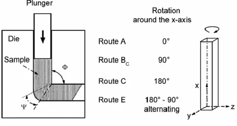
Equal channel angular pressing (ECAP) is capable of producing ultra-fine grained aluminum alloys with improved mechanical properties, and thermal stability by shear deformation27-29. The technique consists of pressing a material through a die with a 90-degree angle without any change of its cross section at the exit (Fig. 6). Due to the die geometry, the material is subjected to a strain value of ~1 during each pass. Various texture and microstructure can be obtained depending on the number of passes and the billet rotation between them, which is dictated by the choice of extrusion route30-32. Four routes have been identified for the ECAP process (Fig. 6): Route A (no rotation of the bar after each pass), Route Bc (the bar is rotated by 90 degrees in the same direction around the X axis between each passes), Route E (the bar is rotated by +/- 90 degrees alternatively after each pass), Route C (the bar is rotated by 180 degrees after each pass)28. Route Bc was found to produce the most homogeneous, and fine microstructure for FCC metals
10
because of the high number of intercrossing slip systems on the X, Y and Z planes28, 33. Thus, it is the optimum processing route for UFG aluminum alloys.
Figure 6: Principle of equal channel angular processing (ECAP). Illustration of the ECAP routes designations. Reprinted with permission from L. Kru¨ger, F. Schwarz, M. Mandel, M. Hockauf, Electrochemical corrosion studies of ultrafine‐grained aluminium alloy EN AW‐6063, Materials and Corrosion 2015, 66, No. 3.34
2.4.1 Dynamic Recrystallization and Shear Banding
Shear bands are narrow regions of localized plastic deformation and heat common in materials deformed at high strain rate including SPD processes35, 36. They are mainly made of elongated subgrains surrounded by low-angle boundary (misorientation < 15 degrees) which evolve to fine equiaxed grains with high-angle boundary when the strain increases36-38. Shear band formation was found to promote grain refinement during ECAP through a mechanism called dynamic recrystallization (DRX)39which has been extensively studied by Meyers et al.40-42. The proposed mechanism starts by the formation of a high density of dislocations during deformation that rearranges in low-energy dislocation cells (subgrains), then evolve to elongated subgrains38. The thermal energy stored in the shear bands may induce the rotation of the subgrain boundaries and the formation of fine equiaxed grains40-42.
11
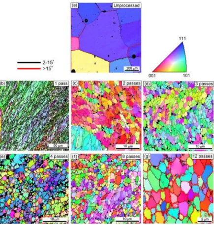
Figure 7: Microstructure and grain boundary misorientation evolution during ECAP. Reprinted with permission from Kawasaki, Megumi, Zenji Horita, and Terence G. Langdon. "Microstructural evolution in high purity aluminum processed by ECAP." Materials Science and Engineering: A 524, no. 1-2 (2009): 143-150.38
2.4.2 Dislocation Density, Grain Size, Grain Boundary Characteristics
Several studies investigated how dislocation density, grain size, and GB misorientation evolve with the number of ECAP passes following Route Bc37, 43, 44. It was found that the microstructure after 1 pass consists of elongated subgrains surrounded by LAGBs parallel to the shear direction (Fig. 7). After 2 passes, the average subgraing size, the aspect ratio of the elongated subgrains, and the fraction of LAGBs decrease while the dislocation density increases rapidly. After 4 passes the microstructure is composed of a mix of fine equiaxed grains and elongated subgrains surrounded by HAGBs and LAGBs37, 38, 43 (Fig. 7). Between 4 and 8 passes the average cell size decreases further as well as the dislocation density and the fraction of HAGbs. The
12
microstructure at the end of this stage is near full recrystallization37, 38, 43. There is no significant change in the fraction of HAGBs and average grain size between 8 and 12 passes (Fig 7-10). They seem to reach a plateau although the fraction of recrystallized grains and dislocation density keep increasing. The microstructure is not fully recrystallized at the end of this stage37, 38, 43.
Figure 8: Schematic of the evolution of grain boundary misorientation in pure aluminum after ECAP following Route Bc. Reprinted with permission from Kawasaki, Megumi, Zenji Horita, and Terence G. Langdon. "Microstructural evolution in high purity aluminum processed by ECAP." Materials Science and Engineering: A 524, no. 1-2 (2009): 143-150.38
13
Figure 9: Modelling of the evolution of average cell size after ECAP with/without the use of backpressure (BP). Reprinted with permission from Mckenzie, P. W. J., Rimma Lapovok, and Y. Estrin. "The influence of back pressure on ECAP processed AA 6016: Modeling and experiment." Acta Materialia 55, no. 9 (2007): 2985-2993.43
2.4.3 Influence of Hydrostatic Pressure
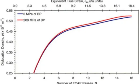
Backpressure (BP) is used during ECAP processing to increase the number of passes (maximal amount of strain) and ultimately the grain refinement and the mechanical properties of the material37, 43, 44.McKenzi et al.43 modelled the evolution of dislocation density in the cell interior, and the average cell size with the number of ECAP passes using a backpressure of 200 Mpa for an AA6016 aluminum alloy (Fig. 9 & 10). They found a good correlation between the use of hydrostatic pressure, the rapid increase in dislocation density, and the decrease in grain size (Fig. 9 & 10). Later Mogucheva et al.37 found that hydrostactic pressure increases the hardness distribution in the material and the stress distribution during deformation. This results in a significant decrease of the amount of material wasted after each passes; an important criteria for commercial applications37.
14
Figure 10: Evolution of dislocation density in the cell interior after ECAP with/without the use of backpressure (BP). Reprinted with permission from Mckenzie, P. W. J., Rimma Lapovok, and Y. Estrin. "The influence of back pressure on ECAP processed AA 6016: Modeling and experiment." Acta Materialia 55, no. 9 (2007): 2985-2993.43
2.5 Ultra-Fine Grained Aluminum Alloys 6xxx 2.5.1 Dynamic Precipitation
In pure aluminum strengthening following ECAP was attributed to the grain refinement as a result of the Hall-Petch law45, and the formation of a high density of dislocation. For aluminum alloys, there is an additional contribution of the intermetallic compounds, and the hardening precipitates initially present in the material29 whichact as barriers to dislocations motion. Roven et al.46 found in Al-Mg-Si alloys that spherical β” (Mg2Si) precipitates formed during deformation even when the material is extruded in solution heat treated condition at room temperature. Similar metastable β” (Mg2Si) precipitates was found earlier by Cabibbo et al. in an AA6082 alloy extruded at room temperature11. This was explained by a dislocation assisted mechanism called dynamic precipitation46, 47. It was suggested that precipitation is promoted by the high density of dislocations (preferred sites for precipitation) generated during the plastic deformation (figure 11).
15
Therefore strengthening in as-ECAPed Al-Mg-Si results from the grain refinement (Hall Petch law), and the metastable β” (Mg2Si) precipitates (Orowan law)11.
Figure 11: TEM images of spherical/globular Mg2Si precipitates in an AA6082 alloy (a) After 1 ECAP pass (b) after 6 ECAP passes. Reprinted with permission from G. Angella, P. Bassani, A. Tuissi, and M. Vedani, “Aging behaviour and mechanical properties of a solution treated and ECAP processed 6082 alloy,” Materials Transactions, vol. 45, no. 7, pp. 2282–2287, 200447
2.5.2 Influence of Aging Treatment
Several combinations of ECAP processing and aging treatment have been investigated in the literature to maximize the mechanical properties of ECAPed aluminum alloys. Ferrasse et al.48 first investigated the effects of a pre-ECAP aging treatment at 170 ⸰C up to 8h on the strength of an AA6061 aluminum alloy. The study found that such a pre-aging treatment leads to a more homogeneous and finer microstructure. It also increases both the strength and the ductility of the material48. Reasons are the small precipitates formed during the pre-aging treatment that prevent grain growth by pinning the GB while acting as a more effective barrier to dislocation motion than the dislocations itself. Later Kim et al.49 found that a low-temperature post-ECAP aging treatment at 100 ⸰C is more effective than the pre-ECAP aging treatment in strengthening AA6061 aluminum
16
alloys. Indeed, the largest increase in yield strength (425 MPa) and ultimate tensile strength (460 MPa) was obtained after 6 passes and a post-aging treatment at 100 ⸰C for 2 days (~ 8% of ductility)49. It is 40% higher than the UTS of the unprocessed material (~ 250 Mpa). This is explained by the formation of fine precipitates (~ 20 - 40 nm) especially at the dislocations generated during ECAP. Indeed, they enhanced precipitation kinetics by decreasing the peak aging temperature from 170 ⸰C to 100 ⸰C, and by suppressing recovery49, 50. The study also found that the common needle-shaped β”(Mg2Si) and lathe-shaped β’(Mg2Si) precipitates found in cast AA6061 after peak-aging are replaced by globular/cluster Mg2Si after ECAP due to higher GB diffusion rate49, 50.
2.5.3 Fragmentation of Precipitates and Particles
Several studies investigated the particles evolution (IMCs, hardening precipitates) during ECAP processing. As a general conclusion, ECAP is effective to break the precipitates into fine particles through shearing and to homogeneously distribute them in the matrix11, 24, 51, 52. This leads to additional strengthening through particle/dislocation interaction11 as they are more effective obstacles to dislocation motion than the dislocation itself. Particle fragmentation during ECAP was reported for Mg2Si precipitates and AlFeSi IMCs in AA6082 alloys11, for Al2Cu precipitates53 in AA2024 alloys and MgZn2 precipitates in AA7050 alloys54. Indeed when the material is extruded following Route C, the particles rearrange along the extrusion direction at the beginning of the deformation before being homogeneously redistributed in the matrix11 while for Route Bc, they rearrange along the shear direction.
17 2.6 Corrosion Mechanisms in Aluminum Alloys 2.6.1 Passivation
The superior corrosion resistance of aluminum alloys is due to their natural tendency to form an aluminum oxide film (1~ 3 nm thick) at their surface that greatly acts as barrier protection for corrosion. Passive films mechanism and kinetic growth models were first proposed in the 30s by Verwey55. It was suggested that film growth kinetic is controlled by cations exchange within the passive film that use an electric field as a driving force. This theory known as high field model (HFM) was later modified by Mott Cabera56, 57who suggested that the cations exchange does not occur within the passive film. Instead, the cations, after being released by the metal transfer to the film at the metal/passive film interface. In the ’80s MacDonald et al.58-60 published a series of paper on a new mechanism called point defect model (PDM) which involved metal/electrolyte interactions. In addition to the cation/cation transfer at the metal/passive film interface, the PDM model included cation/anion/vacancies transfers and mobility between the electrolyte and the metal. However the passive film of aluminum alloys is not fully protective and resistant to chloride ions in particular. It can be susceptible to localized breakdown that results in pits formation, and the anodic dissolution of the aluminum matrix60.
2.6.2 Pitting and Passivation Breakdown
Pitting is the most dangerous and common form of localized corrosion in aluminum alloys. It is an autocatalytic process impossible to predict and monitor due to the stochastic nature of the phenomenon61. Pit growth mechanisms in aluminum alloy, in particular, have been extensively studied by Frankel and al.62. Although pitting has been investigated for many decades, the mechanisms for passive film breakdown and pit growth are still not well understood. Three main
18
models have been proposed to explain passive film breakdown when exposed to Cl-rich electrolyte61: The first one suggests that pitting starts by the adsorption, the penetration, and the transport of Cl- ions in the passive film63, 64. The second model suggests a competitive adsorption mechanism of Cl- and O2- in the passive film which promotes the release of metal ions into the electrolyte65-67.The third one suggests that the passive film breaks because of mechanical stress due to an excess of pressure within the film following the adsorption of aggressive ions68, 69.
Nevertheless, it is well accepted that pitting occurs62 in 3 steps:
Pits nucleation or initiation as a result of passive film breakdown after adsorption of aggressive ions (Cl-) at the film interface.
Metastable pits propagation and growth, characteristic of pits which, nucleate and grow to a certain size for a limited amount of time, and repassivate.
Stable pits propagation and growth as long as the pit environment and pit interior are acidic enough to keep consuming the surrounding aluminum matrix.
Pits formation results from an electrochemical reaction between the metal and the oxygen dissolved in water; the two main anodic and cathodic reactions70. It is followed by the precipitation of aluminum hydroxides; the main corrosion products found inside and at the vicinity of the pits70. These processes70 can be summarized as the following:
Anodic reaction: Al Al3+ + 3e- Cathodic reaction: O2 + 2H2O + 4e- 4OH-
Precipitation: Al3+ + 3H2O Al(OH)3 + 3H+
The most common technique to assess the pitting corrosion susceptibility of a material is polarization measurement during which either the material's potential (E) or the current flow (I)
19
are monitored71. The breakdown potential (Epit) derived from the E = f(I) curve is generally used as criteria to screen the stability of a passive film, and the ability of a material to form stable pits at its surface62. Stable pits form at potentials more active than Epit and grow at potentials more active than the repassivation potential (Erep). These two potentials are measured during cyclic potentiodynamic polarization testing when the potential or current are monitored while the sample is polarized70. Besides, the difference between Erep and Epit, which represents the size of the hysteresis loop, indicates the ability of the pits to repassivate. In other words, higher pitting and repassivation potentials suggest lower susceptibility to pitting, however, this rule should be used with caution because of the stochastic nature of the phenomena and the sensibility of these potentials to material inhomogeneity, the scan rate, and the chloride concentration62.
2.6.3 Influence of Alloying Elements
In aluminum alloys, pitting corrosion generally occurs at the vicinity of the precipitates, and the intermetallic compounds (IMCs)72. However, aluminum is one of the most reactive elements of the EMF series, followed by Mg and Zn73. Therefore any cathodic Fe, Si, Cu-rich particles in the aluminum matrix will favor its dissolution while any anodic Mg, Zn-rich particles will dissolve in favor of the aluminum matrix72, 74. The formation of IMCs compound is the primary cause for passive film breakdown in aluminum alloys. For instance, in the 6XXX series, Al-Fe-Si IMCs are preferential sites for pits formation due to their Fe content72. However anodic phases can lead to pits nucleation and growth as well. This is the case for the S-phase (Al2CuMg) in Al 2024-T375. The mechanism starts with dealloying of Mg and Al leaving cathodic Cu-rich precipitates in the matrix. The occurrence and severity of pitting corrosion is influenced by the size and spacing
20
of the precipitates. Indeed it was found that precipitates smaller than a critical size limit don’t induce pitting while larger precipitates do76.
2.6.4 Intergranular Corrosion
Intergranular corrosion (IGC) is the second form of localized corrosion in aluminum alloys during which the grain boundary chemistry is electrochemically different from the surrounding matrix77. IGC mainly occurs following precipitation hardening78 or sensitization treatment79 during which GB precipitation occurs leading to micro-galvanic cells and precipitates free zones (PFZ)80 at the vicinity of the GB. For instance in Al-Cu alloys (2xxx series) cathodic Al
2Cu precipitates form during aging treatment at the GB while anodic β-phase (Al2Mg3)78 precipitates form in Al-Mg alloys during sensitization. However, the IGC resistance of aluminum alloys is usually improved by optimizing the heat treatment temperature and time which can alter the mechanical properties of the material.
Aluminum alloys from the 6xxx series are mostly susceptible to IGC in their extruded form after aging treatment because of its GB characteristics (HAGBs) and the formation of PFZ80. However their susceptibility to IGC can be reduced by optimizing the amount of Cu and Mg/Si ratio81-83 in the material in addition of optimizing the heat treatment conditions84, 85.
2.7 Corrosion Susceptibility of Ultra-Fine Grained Aluminum Alloys 2.7.1 Effects of SPD on Grain Size
We mentioned in the previous sections that SPD processes induce several microstructural changes in the material regarding grain size distribution, GB density and misorientation, residual stress, and dislocation density. Although most of the studies found that SPD decreases the anodic corrosion current density of aluminum alloys above Epit86-92 couple groups either found that the
21
Table 1: Literature review: Influence of SPD processes on the corrosion susceptibility of pure aluminum
anodic current density is unaffected34, 93, 94 or increase95 after SPD even for the same material processed by the technique (cf. Table 1 and 2). A similar observation is made for the polarization resistance Rp, used to assess passive film resistance under a small sinusoidal perturbation (+/- 10 mV). Some groups found that Rp increase after ECAP86, 87, 89-91, 93, 96while others found a decrease in Rp with SPD. The most controversial results exist for the pitting potential (Epit) and the corrosion potential (Ecorr). There is no general agreement on the evolution of Ecorr and Epit with SPD. A possible reason is the sensibility of the final microstructure to processes parameters (especially the extrusion speed), the initial state of the material (T6 condition or after solution heat treated), the number of passes, and the initial amount of IMCs. For instance some studied used an extrusion
Processing Testing
Environment Ecorr Epit Rp
anodic current density Reference Al 1050, ARB, 9 passes, RT 0.3 M H3BO3 + 0.001 M Na2B4O7
x increase increase decrease [86]
AA1050,annealing at
370 ⸰C for 7200 s ARB 9 passes RT
0.3 M H3BO3
+ 0.1 M NaOH x increase increase decrease [87]
Al-5,4 wt% Ni Al-5wt% Cu ECAP 6 passes RT Route Bc 33 mm/s 0,075 M Na2B4O7 + 0,3M H3BO3 + 0,002M NaCl decrease decrease x x [88] ECAP, 16 passes 0.5 mm/s, RT 0,01 mol/L Na2SO4
+ 3,5% NaCl decrease increase increase decrease [89]
AA1050, ECAP, RT
Route Bc, 16 natural sea water decrease decrease increase decrease [90]
Al 1100 , ECAP 8 passes, Route Bc
0,1 M/L Na2SO4 +
8,46 mmol NaCl increase increase increase unaffected [93] AA1050, Rolling
+ ECAP, 5 passes
0,1 M Na2SO4
+ 100 ppm Cl- unaffected increase increase decrease [91]
Pure Aluminum
22
speed of 0.5 mm/sec89 others 25 mm/sec96 and 50 mm/sec34. However, the extrusion speed is known to influence strain localization, DRX and therefore localized corrosion97. Also, the choice Table 2: Literature review: Influence of SPD processes on the corrosion susceptibility of aluminum alloys
of ECAP route affects the shape of the grains (equiaxed grains, lamellar, mixed) and the shear bands network of the material28, 29. Table 1 and 2 show that some studies extruded the material following Route Bc87, 88, 90, 95 others Route E34, 96 and Route A98. Besides, the maximum number of passes achieved combined with the choice of ECAP Route influence the homogeneity of the material regarding GB characteristics (HAGBs, LAGBs) and particles distribution as discussed earlier. For example, some studies assessed the corrosion susceptibility of the material after 4 passes94 other up 12 passes99 and 16 passes89. In other words, the intrinsic length scales (grain boundary, precipitates, IMC, dislocations) introduced in UFG materials after SPD, and the large
Alloys Processing route Testing
Environment Ecorr Epit Rp
anodic current density
Reference
Al-Si Room temperature HPT
1/4, 1/2, 1, 10 revolutions 3,5 wt% NaCl increase increase increase decrease [92] Annealing 500 ⸰C for 24
hours ECAP RT 5 passes Route A
3 wt% NaCl unaffceted increase unaffected x [97]
AA6082- T6 - ECAP RT 8 passes, Route E
25 mm/min
0,1 M NaCl increase increase increase x [98]
AA6063, ECAP, RT 6 passes, Route E 50 mm/min, Aging at
170⸰C for 23 min
0,01 M NaCl unaffected unaffected x unaffected [95]
Al-Cu-Li AA2024 ECAP at RT
4 passes, Route Bc 0,5 mol/L NaCl unaffected x unaffected [94] Al-Mn Anneling at 573 K for 1hr
ARB at RT , 5 passes 3,5 wt% NaCl increase x x increase [96] Al-Mg ECAP , 12 passes,
Route Bc
0.1 M NaCl
0.01M NaCl x unaffected unaffected unaffected [99] Al-Mg-Si
corrosion behavior complex. 2.7.2 Effects of SPD on Passivity
The effects of SPD processes on the stability and characteristics of the passive film was assessed by potentiodynamic polarization, and electrochemical impedance spectroscopy in the literature90, 92, 100 96. Some groups did not find a change in passivation behavior following SPD processes94 while others found that the passive film of UFG aluminum alloy is thicker, more adherent, and more resistance after processing. The latter conclusion was made after reporting higher values of polarization resistance (Rp), lower passive current density and higher breakdown potential (Epit)92, 101, 102 following ECAP . Such enhancement of passivation behavior was attributed to:
1) The fragmentation of particles (IMCs, precipitates) during SPD below a critical size76 which leads to smaller microgalvanic cells in the matrix.
2) The lower surface electron work function (EWF) of UFG materials compare to their coarse grains counterpart materials. Indeed it was reported for an aluminum 2099 alloy that SPD processes decrease the surface EWF because of the grain refinement102. Also, low surface EWF is associated to higher surface activity which could enhance the ability of the material to passivate102.
3)Higher oxygen adsorption due to the high density of defects generated in the material after SPD. Indeed diffusion is known to be faster on defects (dislocations, particles, grain boundaries) than in the bulk103. Therefore the increase of oxygen diffusion kinetics in UFG may promote the formation of a thicker and more stable passive film101, 102. However, Bruner et al. measured by XPS the atomic concentration of oxygen in the passive film of an Al-Mg alloy processed by ECAP.
24
processed by ECAP which results in a similar thickness of the passive films99. 2.7.3 Effects of ECAP on Pitting Corrosion
Pitting in aluminum alloys is greatly affected by the size and spacing of the IMCs. The larger and closer the IMCs the larger the pits. The reason is the size of the microgalvanic cells formed between the cathodic IMCs and the aluminum matrix. In Al-Mg-Si aluminum alloys, the main IMCs; preferred sites for pitting; are the α-AlFeSi and β-AlFeSi phases98. Several studies reported a change in the pitting attack from a low density of deep pits to a high density of less deep pits following ECAP34, 96,101 attributed to the fragmentation of IMCs during processing11, 51, 104. The corrosion attack morphology is mainly characterized by pits with [111] facets surrounded by filiform corrosion94, 97 along the shear direction also reported as “crystallographic pits (Fig. 12). 2.7.4 Effects of Grain Boundary Misorientation
EBSD37, 38, XRD51 and 3D-APT99 are three common techniques used in the field of GB engineering to investigate GB misorientation, grain texture, and grain size distribution. These techniques were used to investigate how SPD processes change GB misorientation from low angle boundary (LAGB) (misorientation< 15 degrees) to high angle boundary (HAGB) (misorientation >15 degrees)37, 38 when the strain increases. HAGBs are more susceptible to precipitation than LAGBs because of their high GB energy. The use of coincidence site lattice (CSL) approach also demonstrated that they are more prone to IGC in an AA5083 aluminum alloy after ECAP where precipitation of thick β (Mg2Al3) phase in conjunction with higher degree of sensitization (DOS) were found at the HAGBs105. Enhanced IGC susceptibility was also reported for conventionally extruded AA6061-T6. It was attributed to the formation of precipitates free zone, and GB
25
precipitates at the HAGB80. In contrast coherent twin boundaries (Σ3 and Σ7) having low misorientation (LAGBs) were found to be the most resistant to IGC106-108. A recent study confirmed the link between thin β precipitates, low DOS and a high fraction of low grain boundary (Σ<29) in an Al-Mg alloy109. As a result the higher the GB misorientation, the higher the susceptibility to GB precipitation and IGC.
Figure 12: SEM images showing the effects of the number of ECAP passes following route Bc on the pits morphology of an AlMg alloy after potentiodynamic polarization in 0.1 M NaCl (a) CG state, (b) 4 passes, (c) 8 passes and (d) 12 passes. Reprinted with permission from Brunner, J. G., J. May, H. W. Höppel, M. Göken, and S. Virtanen. "Localized corrosion of ultrafine-grained Al–Mg model alloys." Electrochimica Acta 55, no. 6 (2010): 1966-1970.94
2.7.5 Effects of Grain Stored Energy
Several groups reported corrosion at GB with no evidence of GB precipitates. Indeed, in an AA2024-T3 aluminum alloy, GB and grain interior dissolution were observed in isolated grains not decorated with ϴ phase (Al2Cu) 110. However the surrounding grain exhibits a high dislocation
26
density (associated to a high stored energy), suggesting a correlation between grain-stored energy, thermodynamic instability and IGC110-114.
2.7.6 Effects of Residual Stress and Strain Localization
Residual stress was reported to affect the integrity of the passive film, the metal-free energy and the electron work function115 (EWF). EWF is by definition the minimum energy required to remove an electron from a solid surface in vacuum116. It can be measured by scanning Kelvin probe (SKP) or indirectly assessed by Volta potential difference (VPD) measurements using the scanning Kelvin probe force microscopy (SKPFM) technique117. EWF is affected by changes in
Figure 13: (a) Local micro strain distribution in an AlMgSi0.5 alloy after 1 ECAP pass. M = Matrix, SB = Shear Bands. (b) Potentiodynamic polarization curve of the shear bands and the matrix in an aerated 0.1M NaCl solution. Reprinted with permission from Nickel, Daniela, et al. "Effect of strain localization on pitting corrosion of an AlMgSi0. 5 alloy." Metals 5.1 (2015): 172-191.97
the crystal structure (bond length, lattice distortion)115,118 induced by the introduction of compressive or tensile stresses in the material surface. This is the case for SPD processes such as HPT, ARB, and ECAP after which some residual strain, highly localized within the shear bands, remains in the material. Nickel et al.97 investigated the interaction between strain localization and
27
pitting in an UFG Al-Mg-Si alloy by local strain measurements and local electrochemical testing. The results revealed enhanced pitting susceptibility in regions of high residual strain. These regions coexist with the shear bands (Fig. 13) of the material confirming that strain localization and shear banding disrupt passive film stability97, 119.
2.8 Application of Ultra-Fine Grained Aluminum Alloys
Conductive aluminum wires are generally made of Al-Mg-Si alloys by cold drawing as they exhibit the highest strength/electrical conductivity balance. In metallic materials, strength and electrical conductivity are mutually exclusive properties. Indeed the defects introduced in the microstructure to increase the strength are somehow detrimental to electron scattering, responsible for the electrical conductivity. However ARB120 and HPT121, 122 were proved to produce nanostructured Al-Mg-Si alloys with enhanced electrical conductivity and strength through grain refinement, and the precipitation of nanosized Mg2Si precipitates in the matrix.
28
3. EFFECTS OF STRAIN LOCALIZATION ON THE CORROSION BEHAVIOR OF ULTRA- FINE GRAINED ALUMINUM ALLOY AA6061
3.1 Introduction
It has been nearly three decades since the emergence of severe plastic deformation techniques (SPD) have progressed as a viable approach for grain refinement and the development of a good combination of strength, ductility, and thermal stability in metal alloys29, 123. Although the influence of SPD processes on microstructure and mechanical properties has been extensively studied, there remain many uncertainties and controversial results regarding the corrosion resistance of such processed metals112, 114, 124, 125. Indeed the main challenges in this area of research are the sensitivity of the final microstructure to process conditions (temperature, pressing speed, and aging time/temperature) combined with the large number of processing routes inherent to these SPD techniques121. Also, the intrinsic length and size scales (grain boundary area, dislocation density, precipitate morphology, and distribution), helpful for strengthening and grain refinement, add complexity to the understanding of corrosion mechanisms.
In this study we investigate the influence of a particular feature, often disregarded in corrosion studies: adiabatic shear bands. Shear banding is a dominant plastic deformation mechanism for grain refinement in high strain deformation processes such as ball milling, shot peening, wire drawing, high compression tests23, and equal channel angular pressing (ECAP)126. The resulting microstructure is often composed of a high density of micro shear bands which are
Reprinted with permission from "Effects of strain localization on the corrosion behavior of ultra-fine
grained aluminum alloy AA6061." by Ly, Ramatou, Karl T. Hartwig, and Homero Castaneda. 2018, Corrosion Science, 139, pp. 47-57, Copyright 2019 by ELSEVIER.
29
helpful for recrystallization127. More importantly, these bands are regions of high strain localization and transient adiabatic heat, with a complicated thermomechanical history. Strain localization and plastic deformation are critical factors in corrosion. They have been reported to affect surface roughness and passive film thickness, known to control localized corrosion susceptibility115. Pitting and intergranular corrosion (IGC) are the two main types of localized corrosion in aluminum alloys. In general, pitting results from the breakdown of the passive film around particles in contact with a chloride-rich environment62, 126. IGC is a different form of localized attack adjacent or along the grain boundaries (GBs), due to the chemical segregation of particles at the GB either more or less noble than the matrix77. These two forms of corrosion, governed by heat treatment parameters and alloying elements84, 128, make strengthening of aluminum alloys challenging if the goal is also corrosion resistance.
ECAP is a widely-known SPD process for producing ultra-fine grained (UFG) materials by shear deformation23, 129 without significant change in the workpiece cross-section. The technique consists of pressing a bar through a die with a 90-degree angle by introducing a high strain in the material as it passes through the die. It has the capability to considerably enhance the strength of aluminum 6xxx alloys when combined with low temperature aging50. The literature on how strain localization, through shear band formation, affects the corrosion susceptibility of nanostructured aluminum is insufficient. However, in processes such as ECAP, shear bands can cover up to 60% of the overall microstructure after a plastic strain of 4-5 and persist at even higher strains (8-10)37, 38, 130. Also, their width, length, and number are highly influenced by the processing routes or strain history127. Most of the relevant studies that have dealt with the effects of SPD processes on localized corrosion of aluminum alloys have involved shear band formation without considering them in their research94, 96, 98, 114, 125. Raltson et al. in their review, “Effect of grain size