Bilateral Teleoperation over the Internet: the Time Varying Delay
Problem
1Nikhil Chopra and Mark W. Spong
Coordinated Science Laboratory
University of Illinois at Urbana-Champaign
104 S. Mathews Avenue
Urbana, Ill. 61801
USA
Sandra Hirche and Martin Buss
Control Systems Group
Faculty of Electrical Engineering and Computer Sciences
Technical University of Berlin
Einsteinufer 17-19
D-10587 Berlin
Germany
AbstractThis paper addresses the problem of time-varying com-munication delay in force reflecting bilateral teleoper-ation. The problem is motivated by the increasing use of the Internet as a communication medium where the time delay is variable depending on factors such as con-gestion, bandwidth, or distance. The well-known scat-tering formalism introduced in [1] preserves passivity of the communication channel in general only for con-stant transmission delay. We demonstrate how to re-cover both passivity and tracking performance using a modified control architecture that incorporates time-varying gains into the scattering transformation and feedforward position control. Experimental results us-ing a sus-ingle-degree of freedom master/slave system are presented
1 Introduction
Bilateral Teleoperation has challenged researchers in both control theory and robotics over the last few decades. The breakthrough was achieved in [1] where
1This research was partially supported by the National
Sci-ence Foundation under grants ECS-0122412, HS-0233314, and CCR-0209202, and by the Office of Naval Research under grant N-14-02-1-0011
the concepts from scattering theory, passivity and net-work theory were used to derive a control law which guaranteed stabilty [2] of the teleoperator indepen-dent of the (constant) delay. These results were then extended in [4], where the notions of wave-variables, impedance matching and wavefilters were introduced. This paper is motivated by the use of the Internet as the communication medium connecting the master and slave manipulators, where transmission delays are variable. For teleoperation over the Internet the de-lay varies with such factors as congestion, bandwidth, or distance, and these varying delays may severely de-grade performance or even result in an unstable system. There has to date been relatively little research on this problem. Some preliminary results are contained in [5, 3]. Recently, some interesting results were obtained in [6]. A simple modification to the scattering transfor-mation of [1] was proposed, that inserts a time varying gain into the communication block which guarantees passivity for arbitrary time varying delays provided a bound on the rate of change of the time delay is known. Readily available network statistics can be used to es-timate the delay variation needed to compute the gain compensation.
Passivity does not guarantee good performance. In this paper we investigate a modified control architecture that introduces time-varying gains into the scattering
transformation [6] and explicitly uses the position data from the master to generate a feedforward position con-trol for the slave manipulator. We demonstrate how passivity and tracking performance can be recovered via such a configuration. The efficacy of the approach is demonstrated experimentally.
2 Background
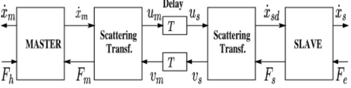
The standard bilateral teleoperation system with the scattering transformation is shown in Figure 1. The scattering transformation approach in [1] or the equiva-lent wave variable transformation proposed in [4] guar-antee passivity of the network block for constant delay in the network. This transformation is given, using the notation of [4], as um= √1 2b(Fm+bx˙m) ; vm= 1 √ 2b(Fm−bx˙m) us=√1 2b(Fs+bx˙sd) ; vs= 1 √ 2b(Fs−bx˙sd)(1) where ˙xm and ˙xs are the respective velocities for the
master and slave. Fh is the operator torque and Fe
is the environment torque. Fm is the force that is
re-flected back to the master from the slave robot. The forceFsis given as
Fs(t) = Ks Z t
0
( ˙xsd−x˙s)dt+Bs2( ˙xsd−x˙s) (2)
where ˙xsd is the velocity derived from the scattering
transformation at the slave side. The power inflow
Delay
MASTER ScatteringTransf. ScatteringTransf. SLAVE
Figure 1:Scattering Transformation for Bilateral Teleop-eration with Time Delay
into the communication block at any time is given by Pin(t) = x˙m(t)Fm(t)−x˙sd(t)Fs(t) (3)
In the case that the network delay is constant we have us(t) = um(t−T)
vm(t) = vs(t−T)
whereT is constant. Assuming that the initial energy is zero, it is easily computed that the total energy stored
in the communications during the signal transmission between master and slave is given by
E= Z t 0 Pin(τ)dτ = Z t 0 ( ˙xm(τ)Fm(τ)−x˙sd(τ)Fs(τ))dτ = 1 2{ Z t t−T um(τ)2+vs(τ)2dτ} ≥0
and, therefore, the system is passive independent of the magnitude of the delay T. The above result does not hold ifT =T(t), i.e., the delay is time-varying. In this case, the transmission equations become
us(t) = um(t−T1(t)) vm(t) = vs(t−T2(t))
where,T1(t) is the delay in the forward path andT2(t) is the delay in the feedback path. We assume here that
dTi
dτ <1 ; i= 1,2
Substituting these equations into (3), the energy stored in the communications is computed as (see [6] for de-tails) Z t 0 Pin(τ)dτ = 1 2{ Z t t−T1(t) um(τ)2+ Z t t−T2(t) vs(τ)2dτ − Z t−T1(t) 0 T0 1(σ) 1−T01(σ)um(σ) 2 dσ − Z t−T2(t) 0 T0 2(σ) 1−T0 2(σ) vs(σ)2} (4) whereσ=τ−Ti(τ) :=gi(τ) andTi0(σ) := dTdτi|τ=g−1(σ).
The presence of the last two terms in (4) show that pas-sivity is no longer guaranteed for time-varying delays. Consider the modified architecture shown in Figure 2, where a time varying gain fi has been inserted after
the time varying delay block. The new transmission equations are given by
us(t) = f1(t)um(t−T1(t)) vm(t) = f2(t)vs(t−T2(t)) MASTER SLAVE Delay Gain Gain Transf. Scattering Transf. Scattering
Figure 2: Time Varying Gainfi(t) inserted in the Com-munication Channel
Computing the total energy as before yields E=1 2{ Z t t−T1(t) um(τ)2+ Z t t−T2(t) vs(τ)2dτ + Z t−T1(t) 0 (1−T 0 1−f12 1−T01 )um(σ) 2 dσ + Z t−T2(t) 0 (1−T 0 2−f22 1−T02 )vs(σ) 2 dσ} (5) Hence, if we choosef2
i = 1−T0i in the above
expres-sions, the second terms are eliminated and the system is passive. In fact, one can see that passivity is pre-served provided the gains,fi, are chosen to satisfy
f2 i ≤1−
dTi
dt ; i= 1,2 (6)
3 Stability
In this paper we first extend the results of [6] to es-tablish Lyapunov stability of the teleoperator with ap-propriately selected time-varying gains to passify the communications. It is assumed that
• The human operator and the environment can be modelled as passive systems.
• The operator and the environmental force are bounded by known functions of the master and the slave velocities respectively.
• All signals belong to the L2e, the extended L2 space.
The master and the slave dynamics are given by Mmx¨m+Bmx˙m = Fh−Fm
Msx¨s+Bs1x˙s = Fs−Fe (7)
whereMmandMsare the respective inertias andBm,
Bs1represent the master and the slave damping respec-tively. The state vector of the system is given as
x,( ˙xm|x˙s|4x) (8)
where 4x=xsd−xs. Define a positive definite
Lya-punov function for the system as V =1 2{Mmx˙ 2 m+Msx˙2s+Ks4x2}+ Z t 0 Fex˙sdτ − Z t 0 Fhx˙mdτ+ Z t 0 (Fmx˙m−Fsx˙sd)dτ (9)
The human operator and the remote environment are passive(by assumption). Hence
Z t 0 Fex˙sdτ ≥0 ; − Z t 0 Fhx˙mdτ ≥0
As the communications are passive(from (5),(6))
Z t 0
(Fmx˙m−Fsx˙sd)dτ ≥0
Thus the candidate Lyapunov function is positive-definite. The derivative of (9) along trajectories of the system is given by ˙ V =Mmx˙m¨xm+Msx˙s¨xs+Ks4x( ˙xsd−x˙s) +Fmx˙m−Fsx˙sd+Fex˙s−Fhx˙m = ˙xm(−Bmx˙m+Fh−Fm) + ˙xs(−Bs1x˙s+Fs−Fe) +Ks4x( ˙xsd−x˙s) +Fmx˙m−Fsx˙sd+Fex˙s−Fhx˙m =−Bmx˙2m−Bs1x˙2s+ ( ˙xsd− 4v)Fs +(Fs−Bs24v)(4v)−Fsx˙sd =−Bmx˙2m−Bs1x˙2s−Bs24v2 ≤0 (10) where 4v = ˙xsd−x˙s. As the derivative of the
Lya-punov function is negative-semidefinite, the system (7) is stable in the sense of Lyanpunov. V(x, t) is lower bounded, negative-semidefinite and its derivative (10) is uniformly continuous in time. Applying Barbalat’s Lemma we see that ˙V(x, t)→0 ast→ ∞. Using this fact and (10) we get that ˙xm, ˙xsand4vasymptotically
converge to zero.
4 Tracking Performance
In the previous section asymptotic stability of the tele-operator, as designed in [6] to handle time-varying de-lays, was demonstrated. The velocity tracking error 4v asymptotically approaches zero but 4x, which is a measure of the position tracking error, is only guar-anteed to be stable in the sense of Lyapunov. Fur-thermore with large delays, as seen in [6], the position tracking becomes quite unsatisfactory. Define the po-sition tracking error as
e=xm(t−T1(t))−xs(t) (11)
where xm(t−T1(t)) is the delayed master position re-ceived on the slave side. To recover tracking perfor-mance, we propose a modified control configuration as shown in Figure 3.
Proposition 1 Consider the additional feedforward control
MASTER SLAVE Delay Gain Gain Transf. Scattering Transf. Scattering
Figure 3:Control Architecture with Feedforward Position Control
acting on the slave robot. Then for a range of the gain (0< Kf < K∗) and appropriate initial statex(0)
sat-isfying
V(x(0))≤Vbound
the state of the system (8) remains bounded. Here satis the saturation function defined as
satp(e) = e |e| ≤p
= p e
|e| |e|> p
Proof To implement this controller, the master posi-tion data are communicated across the channel to the slave side. The equations of motion of the system are now given as
Mmx¨m+Bmx˙m = Fh−Fm
Msx¨s+Bs1x˙s = Ff eed+Fs−Fe (13)
The stability of the system is investigated using the same candidate Lyapunov function (9). Proceeding as before, the derivative along solutions of (13) is given as
˙ V =−Bmx˙2m−Bs1x˙2s−Bs24v2 +Kfsat(xm(t−T1(t))−xs(t)) ˙xs ≤ −Bmx˙2m−Bs1x˙2s−Bs24v2 +1 2{(sat(xm(t−T1(t))−xs(t)) 2+ (K fx˙s)2} ≤ −Bmx˙2m−(Bs1− 1 2K 2 f) ˙x2s−Bs24v2+ 1 2sat(e) 2 ≤ −Bmx˙2m−(Bs1−1 2K 2 f) ˙x2s−Bs24v2+p 2 2 It is easily seen from the above inequality that to ensure stability of the system the feed-forward gainKf has to
satisfy 0< Kf < p 2Bs1 It follows that ˙V ≤0 if ˙xm≥ √2pB m, ˙xs≥ p √ 2Bs1−Kf2 or 4v≥√p
2Bs2. If all the above inequalities are violated,
then from (13) we get, |4x| ≤ |MsL|+√2BBs1p s1−Kf2 + q Bs2 2 p+Kfp+Feb Ks |4x| ≤ c force position control control Sensoray S626 IO Sensoray S626 IO DAC ADC DAC ADC counter counter PC Matlab/Simulink Model RT Linux nication commu-encoder PWM motor strain gauge
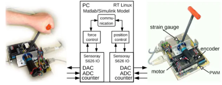
Figure 4: Experimental Testbed
where L is the Lipschitz constant for the compact set ˙
xs≤ √2Bp s1−Kf2
andFeb=|max(Fe)|over the same set.
It is to be noted that the sum of the last three inte-gral terms in (9) is upper bounded(using assumptions and Schwartz inequality). Let this bound be given by Ibound. Define Vbound= Mm p 2 2√Bm +Ms p 2 q 4Bs1−2Kf2 +Ksc2+Ibound
Then all solutions to (13) with initial conditions x(0) satisfying
V(x(0))≤Vbound
remain inside the set defined by V(x(t))≤Vbound
Thus with appropriate feed-forward gain and ini-tial conditions, the state of the system (8) remains bounded. This completes the proof.
The boundedness of the tracking error (11) has not been established and is still an open problem. However it can be argued that in steady state with constant master position, slave velocity and acceleration zero, the tracking error goes to zero (from 13).
5 Experimental Results
In the following experiments the benefits of the ad-ditional position feedforward on position tracking are verified.
The experimental testbed consists of two identical sin-gle degree of freedom force feedback paddles connected to a PC; the original design of the paddles can be found in [7]. The basic configuration is shown in Fig. 4. The paddle DC motor torque is controlled by the PWM amplifier, which operates in current control with the reference given by a voltage from the D/A converter
output of the I/O board. The force applied to the paddle lever, attached at the motor axis, is measured through the bending of the lever by a strain gauge bridge at the bottom of the lever with the strain be-ing amplified and converted by an A/D converter of the I/O board. The position of the lever, measured by an optic pulse incremental encoder on the motor axis is processed by a quadrature encoder on the I/O board. The control loops and the model of the commu-nication channel are composed ofMatlab/Simulink blocksets; standalone realtime code for RT Linux is au-tomatically generated from theSimulink model with a sample timeTA= 0.001s.
All experiments are performed in free space. A
substi-0 10 20 30 40 0 0.5 1 1.5 Delay [s], Gain f 1,1, f2,1 T1, T2 f 1,2, f2,2 (a) 0 10 20 30 40 −1 −0.5 0 0.5 Position [rad] x m(t) x s(t) K f=0; Ks=1 f 1,1, f2,1 (b) 0 10 20 30 40 −1 −0.5 0 0.5 Time [s] Position [rad] K f=0; Ks=1 x s(t) x m(t) f 1,2, f2,2 (c)
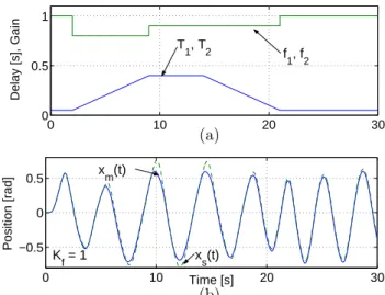
Figure 5: Shockwave phenomenon
tute model of the human operator exerts a force to the open loop force controlled master paddle thereby com-manding the master position xm(t). The master
ve-locity is transmitted via the passified transmission line with the parameter of the scattering transformation set to b = 1, in the first experiment there is no position feedforward, i.e. Kf= 0. The slave is PI velocity
con-trolled with the output ˙xsd(t) of the scattering
trans-formation being the reference and the controller param-etersBs2= 22,Ks= 1 according to (2). The
commu-nication line is modeled by a varying time delayT1(t) in the forward and T2(t) in the backward path, both rising and then falling again with a constant slope of
|T0
1|=|T20|= 0.3, see Fig. 5(a) and Fig. 6(a). Theoret-ically, passivity with respect to the time varying delay characteristic is preserved if the gains f1(t), f2(t) sat-isfy (6), hence they need to be adjusted only when the communication time delay increases, see f1,1(t), f2,1(t) in Fig. 5(a). In the phases of varying and high de-lay tracking performance deteriorates, during decreas-ing delay we observe a shockwave like phenomenon resulting in oscillations of the slave position, a non-recoverable high tracking error remains as shown in Fig. 5(b). After adjusting the gains f1,2(t), f2,2(t) ac-cording to Fig. 5(a) the shockwaves are reduced to an acceptable level, the remaining tracking error is de-creased but still non-negligible, see Fig. 5(c).
In the following experiment we examine the effect of the position feedforward with the same conditions as before, see Fig. 6(a), an additional position feedforward with varying gain, first Kf = 0, then Kf = 1 is
intro-duced. As a contribution to the competitive behavior of the control and the position feedforward control the I-controller parameter and the position feedforward gain are set accordingly Ks= 1 if Kf = 0 and Ks= 0 if
Kf = 1. Stability is preserved throughout the
experi-ment. As we have observed before if the master posi-tion is not fed forward (Kf = 0) then a non-recoverable
position drift occurs caused by the varying delay, see Fig. 6(b). In case of additional position feedforward (Kf = 1) the tracking error e(t) decreases and
con-verges to zero. 0 20 40 60 80 0 0.5 1 1.5 Delay [s], Gain T 1, T2 f 1, f2 (a) 0 20 40 60 80 0 0.1 0.2 Time [s] e 2 [rad 2] K f = 0 Kf = 1 (b)
Figure 6: Squared tracking errore2(t) without and with position feedforward
For a constant master position signalxm(t) = 0 and a
disturbance in the slave position at t= 2s we obtain a similar result: there is a position drift for the standard architecture, the tracking error converges to zero as
0 20 40 60 80 −0.5
−0.25 0
Time [s]
Tracking Error [rad]
K f = 1 K f = 0 x m(t)= 0 Disturbance in x s(t)
Figure 7:Tracking errore(t) for constant master position and disturbance in slave position
predicted in case of additional feedforward, see Fig. 7. In the last experiment a human operator manipulates the force controlled master paddle. The slope of the delay is set to|T0
1|=|T20|= 0.06, the gains f1(t), f2(t) according Fig. 8(a). Again stability and superior track-ing performance is confirmed, see Fig. 8(b).
0 10 20 30 0 0.5 1 Delay [s], Gain T 1, T2 f 1, f2 (a) 0 10 20 30 −0.5 0 0.5 Time [s] Position [rad] x m(t) x s(t) K f = 1 (b)
Figure 8: Master and slave position with position feed-forward and human in the loop
6 Conclusions
In this paper we have extended the scattering formula-tion for teleoperaformula-tion over networks with time-varying delays. A novel approach in order to obtain a stable and transparent teleoperation system using time vary-ing gains and position feedforward has been proposed. Lyapunov stability of the passivation scheme of [6] was established. A feed-forward control scheme has been developed which improves position tracking in the sys-tem without destablizing it. However, no bounds on the tracking error were derived. We hope to address this issue in our future research.
References
[1] Anderson, R.J., and Spong, M.W., “Bilateral Control of Teleoperators with Time Delay,” IEEE Transactions on Automatic Control, AC-34, No. 5, pp. 494–501, May, 1989.
[2] Anderson, R.J., and Spong, M.W., “Asymptotic stability for force reflecting teleoperators with time de-lay,” The International Journal of Robotics Research, Vol. 11, pp. 135-149, April, 1992.
[3] Kosuge, K., Murayama, H., and Takeo, K., “Bi-lateral Feedback Control of Telemanipulators via Com-puter Network,” Proc. IROS96, pp 1380-1385, 1996. [4] Niemeyer, G. and Slotine, J., “Stable Adaptive Teleoperation,”Int. J. of Oceanic Engineering, Vol 16, No. 1, pp 152-162, 1991.
[5] Niemeyer, G. and Slotine, J., “Towards Force-Reflecting Teleoperation over the Internet,”Proc. 1998 ICRA, Leuven, Belgium, 1998, pp.1909-1915.
[6] Lozano, R., Chopra, N., and Spong, M.W., “Passivation of Force Reflecting Bilateral Teleoper-ators with Time Varying Delay,” Mechatronics’02, Entschede, Netherlands, June 24-26, 2002
[7] H. Baier, M. Buss, F. Freyberger, J. Hoogen, P. Kammermeier, and G. Schmidt, “Distributed PC-Based Haptic, Visual and Acoustic Telepresence System—Experiments in Virtual and Remote Environ-ments,” in Proceedings of the IEEE Virtual Reality Conference VR’99, (Houston, TX), pp. 118–125, 1999.