A Systematic Look at Model Transformations
Andreas Metzger
Software Systems Engineering, University of Duisburg-Essen, Schützenbahn 70, 45117 Essen, Germany
Summary. Model transformations are at the heart of model-driven software development (MDSD). As a typical example, models of a higher level of abstraction are transformed into models that are closer to the target platform. However, there are also other forms of such transformations: for example, a model at a certain level of abstraction can be evolved by applying specific designs or modeling patterns.
We believe that a systematic classification of the kinds of transformations that are per-formed during an MDSD activity is of great assistance in understanding such transformations and in comprehending the sources of possible errors and difficulties. This chapter provides a systematic look at model transformations and presents a detailed classification scheme that we have found suitable. To support the soundness of this scheme, we provide examples for its application (i.e., for classifying typical transformations) and we demonstrate how such a classification can assist in understanding some of the problems that can occur within MDSD.
1 Foundation
Before the various kinds of model transformations can be discussed, the central term “model” has to be clarified. In general, “amodelis a set of statements about some
system under study” ([384], p. 27).
To enable the model users to concentrate on the significant system aspects, thus allowing them to handle complexity, any useful model will exhibit some form of
abstractionfrom the system under study. One form of abstraction is the selection of relevant from irrelevant or random properties, which is known asreduction(cf. [281], p. 6). Other important forms of abstraction are generalization and classification. Gen-eralizationis a means by which differences among similar elements are ignored to form an entity in which the similarities can be emphasized ([346], p. 155).Classifi ca-tionis the process of identifying types, which are also known as concepts (cf. [327], p. 12-2 and [346], p. 156). Classification is the basic form of abstraction found in object-oriented or object-based modeling, where object types are the main elements of conceptual models and classes their respective realization in design models (cf. [327], p. 12-3).
In traditional scientific disciplines models are usuallydescriptive, which means that a model can be considered a “correct” description of the system under study if all its statements are true for the system (see [384], p. 27).
In the case of software systems, a model can also be considered as thespecifi ca-tionof a system or rather a whole set of systems that should be built. In the context of such aprescriptive(cf. [281], p. 8) form of model application, which can be found in other engineering disciplines also, a specific system is considered as being “correct” relative to its specification “if no statement in the model is false for the system under study” ([384], p. 27). During software development, the models are refined (i.e., the level of abstraction is reduced), whereby a subset of the initial set of systems is se-lected. If successful, this process leads to thefinal software product, which realizes the desired system in the end.
As is shown in Fig. 1, each model is based on aformalism(or language), which precisely defines the model’s syntax (or notation) and its semantics (or meaning). The syntax of a formalism is made up of the concrete and the abstract syntax. The concrete syntax specifies the readable representation of the abstract notational ele-ments. The semantics consists of the dynamic and the static semantics. The static semantics, which should be more correctly called well-formedness rules (cf. [195], p. 16), is implied by the dynamic semantics and represents restrictions on the set of valid models that can be expressed using the underlying formalism.
Formalism
Concrete
Syntax SemanticsDynamic SemanticsStatic
bases on
represents assigns implies restricts Model Abstract Syntax System(s) abstracts from/ meaning to specifies
Fig. 1.System, model, and formalism (adapted from [55])
With these definitions of system, model, and formalism, we can more formally describe transformations that can occur during software development. Using a
modi-fied form of a formalization that was introduced by Caplat and Sourrouille in [55], we assume thatM is the model of a systemS(or a specification for a set of systems)
andF is the formalism in which the model is described. Any transformationtcan
then be formulated as
t:M1(S1)|F1 →M2(S2)|F2 (1)
2 Classi
fi
cation of Model Transformations
Note that the transformation tthat has been introduced in (1) implies neither that
the source model will be modified nor that the target model will be created without modifying the source model. This characteristic should be considered as being or-thogonal to the transformation that is described byt. Typically, one would consider
the transformation of the latter kind as aquerybecause it is free of side-effects (cf. [12]).
A transformation can bemonolithic (or atomic) or can be composed of many separate steps, which implies a step-wise transformation (cf. [200]).
Caplat and Sourrouille [56] further distinguish model transformations as being
endogenif the formalism of source and target model is the same (F1=F2) or being exogenotherwise (F1=F2).
A further distinction between different kinds of transformations can be exercised upon the purpose of the transformation. There exist transformations that are per-formed to evolve the model and are therefore calledhorizontal transformations. If a transformation is employed for implementing the model, i.e., for transforming the source model into a model that is closer to the run-time platform, we speak of such a transformation as beingvertical(cf. pp. 335–339 in [79]). In thefirst case, the for-malism of the source and target model is the same (endogen transformation), where as in the latter case the target model’s formalism contains elements that describe concepts that are closer to thefinal implementation platform (see p. 119 of this book for an in-depth discussion of the term “platform”). Such a vertical transformation is commonly known ascode generation, when the target model is the actual implemen-tation code (see [12]).
It should be noted that although vertical transformations are exogen transfor-mations, not all exogen transformations have to be vertical transformations. As an example, static analysis tools operate in the reverse direction. These tools usually have implementation code as an input and compute a more abstract model as an out-put. An example is the computation of the cyclomatic complexity for individual code components (see [229], pp. 348–350).
Another characterization can be performed based on the degree to which model transformations can be automated. As each model transformation represents a query and modification of models, such models have to be machine readable and modifiable for automating such activities. Only formal aspects of a model fulfill this requirement and are thus available for a manipulation through software tools (cf. [327]). Conse-quently, if the source and target models’ syntaxes are fully formalized, afully auto-matictransformation is conceivable. Otherwise, manual steps are required allowing forpartially automatedormanualtransformations only.
If a model transformation is exercised by a software tool, this transformation will always be performed in a repeatable and deterministic way. Also, if the trans-formation specification has been systematically tested (see p. 219 of this book) or formally verified (cf. [439]), the chance for introducing errors into the target model is considerably reduced compared to the manual execution of such an activity.
Finally, model transformations can be classified by the technique that is used for describing (resp. executing) the transformations. Two basic approaches for such a description exist: an operational and a declarative approach.
In adeclarativeapproach, transformations are described through rules, which are specified by pre- and post-conditions. The pre-condition describes the state of the model before the transformation is executed. The post-condition specifies the state after a successful transformation. As most of the models or specifications can be expressed as graphs, many of the declarative approaches that are used today are graph transformations (e.g., see p. 91 of this book).
With declarative approaches, a specification of the transformation can be achie-ved, which is often called amapping(see [256]). Nevertheless, we will not distin-guish between “transformation” and “mapping” in the remainder of this chapter but will use the terms interchangeably for readability reasons.
In contrast to declarative approaches, inoperational(or imperative) approaches, the activities which must be performed to transform the source to the target model are described explicitly by a sequence of actions (see p. 480 in [458]).
Czarnecki and Helsen present further approaches for classifying transformations [80]. Among other aspects, they discuss the notions of to-model and model-to-code translations and examine the differences of transformation approaches based on the representation (syntax) of the transformation rules or the form of typing that the “rule language” offers. Favre [120] distinguishes between transformation func-tions (i.e., transformation specifications) and transformation instances (i.e., the ap-plication of a transformation specification to a specific source model).
Although all of the above types of transformations may provide a suitable clas-sification when examining certain properties of model-driven software development (MDSD), we see the need for yet another classification scheme that allows one to reflect on some of the potential pitfalls of MDSD. This scheme is introduced in the following section and is followed by examples for its application in Sect. 3.
2.1 Fine-Grained Classification Scheme
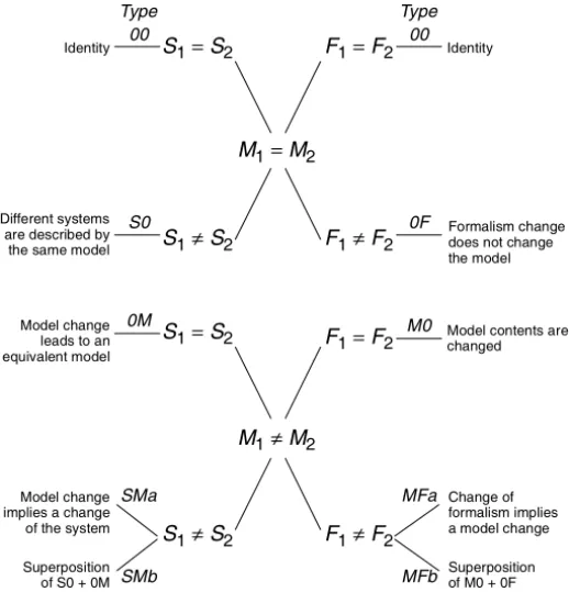
In this section, afine-grained classification scheme is introduced that considers the possible variations of the systems, the potential changes of models, and the varia-tions in the respective formalisms. To begin with, Fig. 2 shows an overview of the identified types of transformations.
As the reader can observe, we have chosen a very simple scheme for naming the different types of transformations by following the graphical layout of the fi g-ure, which should be easy to remember. With this classification scheme, each kind of transformation can be described by a type from the left-hand side of thefigure together with a type from the right-hand side of thefigure.
Not all of the above transformations are “true” model transformations, as some of them do not require any modification of models (M1=M2). However, we will show
that such mappings exist in reality and that these can be helpful when evaluating model transformations.
M1=M2 M1≠M2 F1≠F2 F1=F2 F1=F2 S1≠S2 S1=S2 S1≠S2 S1=S2 F1≠F2 Identity Identity Formalism change Change of Model change Different systems are described by implies a change Superposition M0 00 SMa 00 0F 0M
does not change
Model contents are changed
formalism implies
Superposition the same model
Model change leads to an SMb S0 MFa MFb Type Type of S0 + 0M of M0 + 0F the model equivalent model
of the system a model change
Fig. 2.Classification of Model Transformations 2.2 System and Model Transformations
We start the detailed discussion of our classification scheme by presenting the types of transformations that are introduced on the left-hand side of Fig. 2.
Type S0 Transformations
At the beginning of this chapter, the nature of a model (or a specification) as being an abstraction of a set of systems has been introduced. It is this very nature of a specification that allows several systems to be represented by the same model, thus leading to a “transformation” that can be classified as S0. Whenever two systems differ only in properties either that have been eliminated in the model or that are not reflected in the abstract model elements, we can observe a “transformation” of type S0 between these two systems.
An illustrative example for the abstraction of such a property is provided by Petri nets. In general, a Petri net is a directed bipartite graph with two distinct types of nodes: places and transitions. To describe the dynamics of a Petri net, tokens that can reside within places are introduced. A transition is enabled if and only if there is at least one token in each input place of the transition. When a transition is enabled, itcanfire, upon which a token is removed from each of the input places and a token is generated in each of the output places (for a more detailed introduction
see, e.g., [359]). As the enabling of a transition only specifies itspotentialforfiring, each system that demonstrates any of the possiblefirings of transitions is a correct realization of such an abstract Petri net model.
Type 0M Transformations
There exist model modifications that result in an equivalent model with respect to the modeled system (type 0M).
An obvious example is that renaming an attributeitocountingVariable will result in the very same software system. In fact, there exist tools to obscure variable names in programs to make it difficult to understand the code when it is de-compiled. The user of the program will discover no difference whatsoever.
However, determining the identity of two systems is far from trivial. If, instead of using the variable from above, we were to introduce accessor and mutator methods
(i.e.,getCountingVariable() andsetCountingVariable()), the
sys-tems might still be identical from a given point of view. Nevertheless, the detailed run-time behavior would be different, caused by the timing penalty that is imposed by the method calls. As Kleppe and Warmer observe, there does not seem to be a solution to this problem (cf. [256], p. 19). Yet, for our considerations we believe it is sufficient to look at this problem in a more idealistic way and assume that we can identify equality (even if this was possible for theoretical considerations only).
Type SM Transformations
A transformation of type SM comes in two facets. On the one hand, there is the obvious case that a model change implies the change of the specified system (type SMa). For example, if a UML object model is extended by a new class, the thus extended system will most certainly differ from the original system.
On the other hand, the observed changes of the model as well as the system might be attributed to the superposition of two other types of transformations (type SMb). This is possible if a model change does not imply a change of the system (type 0M), yet the system possesses properties that are not described in the model (type S0).
2.3 Model and Formalism Transformations
Now that the different types of transformations considering the variations of model and system have been discussed, the kinds of transformations that can be found on the right-hand side of Fig. 2 are presented.
Type 0F Transformations
A transformation of type 0F can lead to a change of presentation of the model only, i.e., the concrete syntax of formalismF1 will differ from that of formalismF2. A
change of the abstract syntax or even the semantics of the formalism would force a more drastic change (see type MF below).
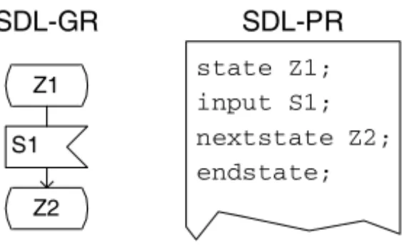
As an example of such a transformation, we introduce the Specification and De-sign Language SDL (see [330]). SDL models can be described in graphical form (SDL-GR) as well as in a textual representation (SDL-PR). In Fig. 3 both forms are presented. The model describes a state transition fromZ1toZ2after the reception of a signal (or message)S1.
Z1 S1 Z2 SDL-GR SDL-PR state Z1; input S1; nextstate Z2; endstate;
Fig. 3.Different representations of an identical model
Type M0 Transformations
Transformations of type M0 could be considered as “true” model transformations because the model information is changed while preserving the model’s formalism.
The above example of adding a UML class to an object model falls into this cat-egory as well as the change of an existing model element (e.g., renaming an attribute of a UML class). Type M0 transformations are the typical horizontal transformations that we have introduced in Sect. 2.
Type MF Transformations
This last type of transformation (type MF) exhibits two facets, as is the case for type SM. First, a change of formalism can imply a change of the model (type MFa). This situation always occurs when the abstract syntax or the semantics of the formalism changes.
To illustrate, if one changes the formalism from UML object diagrams (where objects have dependent control flows per default) to the modeling language SDL (where objects are realized as independent processes), this must have wide-reaching consequences for the model (and if more than one object is modeled, for the modeled system as well).
Additionally, a superposition (type MFb) is possible, i.e. although a (syntactical) change of the formalism has no consequences (type 0F), a “true” model transforma-tion (type M0) is performed.
3 Using the Classi
fi
cation Scheme
After the different types of transformations have been introduced and have been il-lustrated with simple examples, this section presents other more complex examples
for the application of the classification scheme. These include the analysis of trans-formation steps that are performed by a high-level language compiler as well as the classification of activities that are performed within a transformational software development process. Additionally, common transformations that can be found in state-of-the-art MDSD approaches (like OMG’s Model-Driven Architecture [294]) are evaluated. An example is provided for applying the scheme when a horizontal model transformation is performed.
3.1 High-level Language Compiler Transformations
A traditional field of “model” transformations can be found when considering the concepts of high-level language compilers (like C++ or Java compilers, e.g., see [10]).
Source “model”Msfor these compilers is the source code in a high-level
pro-gramming language that should be transformed into the target “model”Mt, i.e., the
machine or byte code of the target platform or virtual machine. As afirst step, an abstract syntax treeMa
s is created by parsing the source code (concrete syntax). This tree, which typically can be found as an internal data structure of the compiler, is then transformed into an abstract syntax treeMa
t that reflects the target model. From this abstract syntax tree, the final “model” in the concrete syntax of the machine or byte code is attained through an unparsing activity. To summarize, the following transformations are performed:
Ms−→0F Msa−→M0 Mta−→0F Mt (2)
Transforming the source model to its abstract representation is a pure formalism transformation that does not affect the actual model. The same holds for the unpars-ing activity. Therefore, both are of type 0F. The transformation of the abstract syntax tree, however, requires a model change because the concepts of the source and target language might differ, e.g., there will be no such concept like afor-loop in the ma-chine or assembler language. Therefore, this usually must be mapped to a conditional branch construct (likebneorbeq).
It should be noted that in many compiler implementations, the transformation is abbreviated by directly transforming the source to the target model, i.e., by employ-ing a transformation of type MFa.
3.2 Transformational Software Development
The essence of transformational software development is that “from a formal
speci-fication of a problem to be solved, programs correctly solving that problem are constructed by stepwise application of formal, semantics-preserving transformation rules” ([345], p. V). It is this very focus on semantics-preserving transformations that allows one to guarantee the correctness of the program by construction.
Typical examples of the application of the transformational approach are the derivation of operational specifications (or code) from a declarative model of the
problem as depicted by Partsch in [345], p. 189. The transformation rules that are presented by the author are special forms of inference rules, the systematic appli-cation of which will lead to an operational specification. Because of the semantics-preserving nature of the inference rules, all transformations within such a transfor-mational software process can be classified as being of type M0.
To allow for the smooth transition from the formal specification to the actual pro-gram, wide-spectrum languages are employed. These languages, in addition to
speci-fication constructs (i.e., more abstract concepts), contain concepts that are known from programming languages (cf. [345], p. 51]. This means that a wide-spectrum language is a formalism with a single and consistent set of conceptual elements ([32], p. 15). Based on our classification scheme, this implies that transformations between “models” that are expressed in such a language are of type 0M.
3.3 MDSD Transformations
As an important and current example the application of our classification scheme, we discuss the typical kind of transformation that occurs within most of today’s model-driven software development approaches, of which the OMG’s Model-Driven Architecture MDA (cf. [294]) is the most prominent example. However, also gen-erative approaches that use the Specification and Design Language SDL (see above) are commonly found here.
In all these casesverticaltransformations are applied to generate models in a less abstract formalism (target model) from models that are described in a more ab-stract formalism (source model). Less abab-stract here means that the target model is closer to the run-time platform than the source model was. In the context of the MDA these transformations occur between thePlatform Independent Model(PIM) and the Platform Specific Model (PSM) as well as between the PSM and the ac-tual implementation code. Currently, many of the MDA tools skip the generation of the intermediate PSM model altogether and directly generate implementation code. Well-known examples of such tools are iLogix’s Rhapsody, gentleware’s Poseidon, or ARTiSAN’s Real-Time Studio. For the modeling language SDL, implementation code is typically also directly generated from models, e.g., when using Telelogic’s Tau SDL Suite.
It is this very transformation of source models to implementation code that we want to evaluate in more detail. However, the results could also apply to any vertical transformation of more abstract source to less abstract target models (cf. [256]).
Understanding what occurs during code generation becomes important especially when the running system is being tested. The assumption that the properties of the source model and the properties of the implementation code are identical can lead to the incorrect identification of errors in the source model, or, worse, can obscure errors.
As both the source model and the implementation code are models (both more or less abstract from concrete systems), the creation of the implementation code from the source model (the PIM in the case of MDA) is a kind of model transformation.
As the formalism of the more abstract model and the formalism of the implemen-tation code usually differ in many aspects, such a transformation inevitably implies a major change of the model. One example of a transformation from a PIM to im-plementation code could be the generation of Java classes from UML classes. Using our classification scheme, such a transformation of the source model to code can be considered a transformation of type MFa, i.e., a “true” formalism and model change. Ideally, the systems that are realized by the implementation code should be a sub-set of the sub-set of systems that is described by the specification (semantics-preserving refinement, see Sect. 3.2). Only this relationship would allow for the verification of the considered properties of the specification (the source model) by employing the implementation code for testing. Within the MDA, a model transformation is even defined to be “the process of converting one model to another model of thesame
system” ([294], p. 2-7). We therefore would have to require a transformation of type 0M. As Kleppe and Warmer observe in [256], such a transformation is only realistic in an ideal situation.
The reason is that in a practical context, the required transformation of 0M is complicated by the transformation of type MFa which was identified above. This implies, in many cases, that the transformation of type 0M cannot even be realized. This can be attributed to the fact that the formalisms of source and target models not only differ considering their syntax but almost always differ in their semantics, i.e., in the basic paradigm of the conceptual elements (cf. [210], pp. 7–8) . Preserving the semantics of the models during an MFa-type transformation therefore almost always will be impossible (cf. [256]).
This fact presents a notable difference to the types of transformations that have been illustrated in the previous sub-sections. Traditional compilers work with input “models” that are at a low enough level such that “purely local optimizations are sufficient” ([27], p. 41). A similar observation holds for transformational program development, when a wide-spectrum language, which presents a formalism with a single and consistent set of conceptual elements ([32], p. 15), is used.
Looking at MFa transformations in more detail, three different kinds of mappings of source model elements to counterparts in the target model can be identified: (1) Non-ambiguous mapping: One or more model elements of the source model can
be mapped to one ore more elements in the target model without losing their meaning (example: an attribute of a UML class can be mapped to a variable in Java). If this mapping can be applied for all model elements, we would arrive at the ideal case of having a transformation of type 0M.
(2) Selection: One or more elements of the source model can be mapped to ele-ments of the target model only after additional decisions have been made. Con-sequently, such a mapping is ambiguous, which implies that a selection among several alternative mappings must be performed.
(3) Approximation: For one or more source model elements, there exist no (seman-tically equivalent) counterparts in the formalism of the target model. Therefore, the elements of the source model have to be approximated as best as possible by using elements of the target model.
The last two cases are obviously the ones that prohibit the desired transformation of type 0M. If there is no direct or no non-ambiguous mapping from elements in the source model to elements in the target model, the resulting systems can hardly be identical.
To give the reader an in-depth understanding of the critical situations that can occur when a selection or approximation has to be exercised, we will present two examples in the SDL. This language is comparable in many ways to the current version of the UML (i.e., UML 2.0). Therefore, similar observations would apply.
Selection
A situation that requires aselectionof a mapping alternative occurs when the parallel processes that are described in SDL have to be realized within a monolithic operating system process, which is typically implemented in the programming language C (this is Telelogic Tau’s approach). To perform such a realization, an execution order of the processes has to be defined to be able to execute them sequentially.
This sequentialization, however, can obscure errors because critical situations, in which the errors would be visible, will never occur. To illustrate such a situation, we introduce a small SDL example (see Fig. 4), in which the model architecture as well as the behavioral description of the individual processes is shown.
system ABCDemo 1(1)
SIGNAL sigA; SIGNAL sigB; SIGNAL go;
producerA chA consumer producerB
sigA go chB sigB go process consumer 1(1) idle receiving go via all
chA, chB sigA sigB
idle receiving receiving process producerA 1(1) idle idle go sigA idle process producerB 1(1) idle idle go sigB idle
Fig. 4.SDL model of a producer/consumer pair
There are three communicating processes: producerA, producerB, and
consumer. Signals fromproducerBcan only be received afterproducerAhas initially sent a signalsigAto the consumer process (the transition fromidleto
receivingis taken). To start communication, the consuming process sends ago signal to both producing processes.
Depending on the order of execution (i.e., whetherproducerAorproducerB is activatedfirst), the consumer process might be able to receive signalsigBor will lose the signal. These two possible scenarios of execution are shown in Fig. 5 as a Message Sequence Chart (MSC; cf. [330], pp. 356–359), which is similar to UML’s sequence diagrams in the form in which it is used here.
If the processes were scheduled according to scenario b) only, the error in the specification would be obscured, as the potential loss of signals could never be ob-served. This implies that even if the tests had been passed for a very specific test case, the test might have failed when a different code generator was used (although there had been no change of the source model whatsoever).
To increase the confidence of such tests, the selection of the properties should always be considered. One could, as an example, generate code alternatives that use a different form of selection and additionally test these alternatives. However, one should keep in mind that the number of possible combinations that must be evaluated might soon reach a limit above which the effort for testing is no longer feasible.
Approximation
Signals that are exchanged between SDL processes are stored in signal queues (cf. [109], pp. 62–63). As a model abstraction, these queues can hold an infinite number of signals. Because of obvious memory constraints, such queues can only be imple-mented as data structures with afinite (although dynamic) length, i.e., the infinite queues are approximated by finite queues. Especially in reactive systems that are executed on hardware platforms with only small data memories, memory overflows can easily occur that cannot be attributed to an error in the specification.
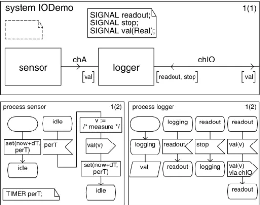
The following example, which is a modified form of an SDL model that is pre-sented in Queins’ Ph.D. thesis ([353], pp. 179–180), depicts this situation in more detail (see Fig. 6).
Using the timer perT, the sensor process periodically measures a certain physical value that is sent to thelogger process. Initially this process is in the
a) b) producerB consumer producerA receiving idle sigB sigA go go producerA consumer producerB
receiving idle go go sigA sigB /* lost */
system IODemo 1(1) SIGNAL readout;
SIGNAL stop; SIGNAL val(Real);
sensor chA logger
val
chIO
readout, stop val
process logger 1(2) logging val readout logging readout process sensor 1(2) idle readout stop logging readout val(v) readout val(v) TIMER perT; via chIO idle idle perT v := /* measure */ val(v) set(now+dT, perT) set(now+dT, perT)
Fig. 6.SDL model of a data logger
loggingstate and does not consume thevalsignals (the rhomboid symbol de-notes that the signals are kept, i.e. “saved”, in the input queue). As soon as the logger process receives thereadout signal from the environment (i.e., when the user wants to receive a readout of the logged sensor data), allvalsignals in the input queue are consumed and a respective signal is sent to the environment until the stopsignal is received.
Assuming that the period dTof the sensorprocess is ∆t and the maximal
queue size of our implementation iss(this upper limit can be imposed by either a
static data structure or the actual memory available to the running system), a memory overflow will occur if thereadoutsignal is not received withins∆tafter system
start.
If the arrival of thereadoutsignal can be guaranteed, the observed fault will not be critical. However, in a reactive system the arrival of external signals can typ-ically not be guaranteed (the user cannot be forced to read out the data before the memory overflow occurs). As a consequence, the source model would have to be changed, although the specification was correct. Unfortunately, this implies that the chosen abstraction might not have been suitable or that the ideal of MDSD might not be accomplished as easily as thought.
Additional Properties
In addition to the properties that differ between the systems that are described by the source and the target model, the target system (in our case the running application) can exhibitadditionalproperties that have not been described in any of the models.
This is a natural consequence of the abstraction that has been employed to achieve the models.
To illustrate, the concrete execution time of an application is a property that is typically not described by standard UML or SDL models. However, the running system will exhibit a very specific run-time behavior and concrete execution times can be measured. Consequently, we can observe a transformation of type S0.
This implies that even if the ideal transformation of type 0M could be achieved by non-ambiguous mappings, the above fact will render this impossible on a more detailed look. In thefield of software prototyping this observation has lead to the suggestion that a prototype that has been validated and accepted by the users should always be kept as part of the overall requirements specification (cf. [54], p. 40). How-ever, the reasons for that have not been discussed in detail.
3.4 Horizontal Transformations
The realization of the vertical transformations in the context of MDSD approaches has been the logical next step in the abstraction and automation process that has been started with high-level language compilers (or even assemblers).
Interestingly, examples of the automation of horizontal (i.e., evolutionary) trans-formations can rarely be found. This might be attributed to the fact that source code – even the one of a high-level programming language – is not semantically rich enough to allow for such an automated evolution. Only with the introduction of modeling languages and domain specific modeling (e.g., through meta-models) does this seem to become possible. Czarnecki and Eisenecker even postulate that the more abstract development information a source model contains, the more automated the support for model evolution can become ([79], p. 338).
One such transformation is the automatic instrumentation of a model for debug-ging or testing purposes. In the SDL example, a special output statement could be added to each transition to monitor the execution of the system. This extension of the model consequently is a transformation of type M0 (the source and the target models are SDL models).
Because the instrumentation will produce additional output, the systems that are
finally derived from such an instrumented model will be different from the systems that are derived from the initial source model. This means that this instrumentation activity has to be classified as being of type SMa. This poses the problem that the system that is being tested (the onewiththe instrumentation) differs from the system thatfinally will be deployed, and thus the results of the tests might become question-able.
Another example of such a vertical transformation is “model refactoring”, which is introduced in detail by Gray et al. on p. 199 of this book.
4 Conclusion
In this chapter, we have shed light on the essential activity that is performed in any model-driven software development: model transformation. After the most
ba-sic terms and current classification schemes were introduced, a morefine-grained scheme has been presented that considers the differences between the modeled sys-tem, the model itself, and its formalism.
With this classification scheme, different examples of transformations have been evaluated. These were transformations performed by high-level language compilers as well as transformations within a transformational software development process. Further, important forms of transformations have been discussed for state-of-the-art MDSD approaches (like MDA), which included vertical transformations (code generation) and horizontal transformations (where the instrumentation of a model has been chosen as an example).
With this classification, problems that are eminent in all model-driven software development approaches have been uncovered and the reasons for their existence have been explained. In detail, we have illustrated why test results that have been attained by testing systems that have been automatically derived from specifications have to be evaluated critically. We believe that understanding what happens during each type of model transformation is an important prerequisite for properly applying MDSD approaches and for correctly using the associated tools. Therefore, we hope that the concepts and views that have been depicted in this chapter will help “model-driven software developers” in solving their challenging yet enthralling tasks.
5 Acknowledgments
I want to thank the anonymous referees for their critical and productive comments that have led to the improvement of this contribution. I further would like to thank Stefan Queins, whofirst brought the difference between a prototype (the target sys-tem) and the specification (the source model) to my attention. I also have to acknowl-edge Christian Floyd’s 1984 paper “A Systematic Look at Prototyping”, which in-spired the title to this chapter. Finally, I am grateful to my aunt Anna-Lee Adams for
![Fig. 1. System, model, and formalism (adapted from [55])](https://thumb-us.123doks.com/thumbv2/123dok_us/9620779.2449627/3.892.178.716.622.893/fig-system-model-and-formalism-adapted-from.webp)