ESE 498 Electrical Engineering
Senior Design Final Project Report
PlugandPlay Engine Sound Replicator
Whitney Flohr Electrical Engineering, Class of 2009 [email protected] Jason Lin Electrical Engineering, Class of 2009 [email protected]ESE 498 Senior Design Page 1
Table of Contents
Abstract ... 2 Introduction ... 3 Project Priorities ... 4 Sensing RPM ... 5 Criteria ... 5Car Adapter Plug ... 5
ODB‐II Connector... 8
Others ... 9
Processing RPM ... 10
Car Adapter Plug ... 10
ODB‐II Connector... 12 Sound Synthesis ... 13 Criteria ... 14 Design Choices ... 14 Memory ... 16 Audio Delivery ... 16 Ethical Concerns ... 17 Future Considerations ... 19 Conclusion ... 19 References ... 21
ESE 498 Senior Design Page 2
Abstract
This project was brought to the department by a third party member, Larry
Heugatter, who noticed spark plug interference noise on his car radio that increased
when he accelerated. He conceived a device which would use this noise to generate
engine sounds of a super car in sync with the car being driven.
While spark plug noise was not a viable option of sensing RPM, two alternate
methods were found. The first was alternator noise on the car adapter plug, an analog
signal that can be processed into a digital signal. The second was the OBD‐II plug,
available in most cars, that communicates on a digital serial protocol.
Experimentation with sound files produced a groundwork for determining how
many files of what size are necessary to produce a clean and realistic sound, as well as
an idea of the memory and processing power that would be required.
In the future, the individual components will need to be integrated into a system
that does not require a laptop to process. Other issues to explore are making the system
wireless to avoid wire tangles, legal issues with using engine sounds, and the question of
distraction.
ESE 498 Senior Design Page 3
Introduction
The motivation behind our project was that many people wish to drive fast cars
like Ferraris and Lamborghinis, due to their stunning looks, incredible speed, and
harmonious sound. Currently there are options on the market for people to modify their
everyday cars, including the use of expensive body kits, engine upgrades, or exhaust
replacements for those who can’t afford such vehicles.
However, such modifications require time, money, and automotive experience.
With the inspiration from Larry Heugatter, our project began as an idea to bring the
glorious sound of six‐figure super cars to everyday people with common cars, without
the automotive experience or intense modifications. Our goal was to find a quick, easy,
and inexpensive way to give a mundane car the sound of a fire‐breathing supercar.
In undertaking this project, there were three major tasks to accomplish. First, we
needed to find a way to monitor a car’s RPM and then convert the analog output into a
digital signal for processing. Second given a signal to process, there was the task of
matching the RPM sounds of a difference car to create the sound effect of driving a high
performance car. Lastly, when these two technical tasks were completed there would
be an actual device that connects to the car, receives power, and emits sound either
through a speaker or through the vehicle’s built in audio system.
ESE 498 Senior Design Page 4
Project Priorities
The project can be divided into several tasks. We decided to focus our work on
the individual components at the expense of working to combine them into a
functioning prototype device. We felt using computers to handle processing and
communication rather than dedicated hardware would make the project more
manageable in the time allotted.
The first step was determining the current state of the car’s engine, so that
engine sounds could be matched to it. Because noise experienced by the driver is most
closely correlated with the rate of the engine firing, or revolutions per minute (RPM), we
sought to detect the RPM in a way that would fulfill the project criteria. This portion of
the project required the majority of our research and experimentation, and was
therefore a top priority of the project.
Second was processing the RPM reading into a useful signal. Tested methods for
sensing RPM would yield either digital and analog signals. In the case of digital signals,
processing involves a well‐documented communication protocol. In the case of analog
signals, conventional filtering and converting components are available as discrete
components. As shown, processing can be done in a straight‐forward manner and was
therefore not given as much priority as sensing.
Lastly was the problem of synthesizing sounds to correlate with the processed
signal. This involves a system to select a sound file to play based on the input signal and
a delivery system for the audio. Because of the aforementioned de‐emphasis on
ESE 498 Senior Design Page 5
achieve good sound, determining the minimum resolution of sound files and focusing on
a delivery system.
Sensing RPM
Criteria
The design for sensing the car’s rpm conforms to the following standards: • The design should be nearly universal. The sensing method/hardware
should be compatible with as many vehicles as possible, either correcting
for differences between different models and makes, or relying only on
components and characteristics that are nearly universal.
• The design should be “Plug‐and‐Play”. The sensing hardware should be
installed easily with few, or ideally no, tools. Removal should be similarly
easy. The installation should not involve opening any panels or getting
under the hood: any parts should be confined to the car’s interior. • Installation and operation should not require extensive automotive
knowledge.
Car Adapter Plug
The car adaptor plug, or cigarette lighter plug, is one of the two viable methods
for remotely sensing the vehicle’s RPM. The plug is often used as a 12V DC power supply
for small devices (phones, PDAs, etc.). Since the battery is connected do the alternator
for charging, it experiences noise from the alternator’s rectifier circuit when the engine
ESE 498 Senior Design Page 6
Measuring RPM through the noise from the alternator through the car adapter
plug meets the criteria established in the previous section. While automotive electrical
systems have become more advanced and better at filtering noise, it is never entirely
erased, and usually correlates with filtering from the cord/device end. Therefore, we
believe alternator noise has the potential to be measured form most cars. Furthermore,
a car adapter plug is easy to install and uninstall, requiring no more automotive
knowledge than installing and uninstalling a car charger for a cell phone.
Fourier analysis of the adaptor plug signal at different engine RPM is shown in
Figure 1, Figure 2, and Figure 3 with the frequency of interest highlighted.
Figure 1: Fast Fourier Analysis of Plug Signal at Approximately 1000 RPM
ESE 498 Senior Design Page 7
Figure 2: Fast Fourier Analysis of Plug Signal at Approximately 1500 RPM
Figure 3: Fast Fourier Analysis of Plug Signal at Approximately 2000 RPM
Aside from the DC component, there is a strong component that moves from
950Hz at idle (approximately 500 RPM) to 3.18kHz at 2000 RPM. The frequency of this
component correlates linearly to RPM over the range tested, where:
RPM=0.64*frequency
3.18 kHz
2.27 kHz
ESE 498 Senior Design Page 8
OBDII Connector
The OBD‐II (On‐Board Diagnosis Connector) is a standardized connector, shown
in Figure 4, required on vehicles sold in America for all models after 1996. The system
can both store data, and provide real‐time read outs for various engine information
such as engine temperature, speed, error codes, and RPM. Several different standards
exist for the OBD‐II, outlined in Table 1. Model years 2009 and later will all use the CAN
standard.
Figure 4: Pin Layout of OBD‐II Connector
Pin Usage on OBD-II Port by Standard
Standard Usage Pins used
Pulse Width Modulation Ford 2,4,10,16
Variable Pulse width Chevy 2,4,16
ISO 9141-2 European and Asian
Models
4,7,15,16
KWP200 4,7,15,16
CAN Mandatory Standard
for 2009 and beyond
4,6,14,16
Table 1: Pin usage and manufacturers by OBD‐II standards
Though many standards are used, there are parts available that convert the
signal into a serial binary in RS‐232 standard. Specifically ELM electronics produces a
chip that automatically senses the standard being used based on pin activity. Using this
ESE 498 Senior Design Page 9 The OBD‐II standard, also meets the sensing criteria. Engine RPM measurement
is uniformly supported across all OBD‐II platforms and with the support of a chip like the
ELM327, RPM can be read out of cars made since 1996. The OBD‐II port in a car is
located in the cab, typically under the steering column. While the port’s location is not
common knowledge it is easily accessible and requires little automotive knowledge
Others
Several methods of sensing failed to meet the previously stated criteria. At the
onset of the project, we sought to measure vehicle RPM by measuring the radio noise
generated by sparkplug firing. This method did not meet the universality requirement.
Sparkplug manufacturers have worked to decrease this noise. Low noise sparkplugs,
previously found mainly in areas where radio was critical, for example nautical engines,
are now found in a large number of automobiles as well. There is no way of knowing if
this method will work with a given car, without knowing whether or not a user has a low
noise sparkplug.
Directly sensing the current across the spark plug would most accurately
determine vehicle RPM, but would require the user to have automotive knowledge and
the ability to install devices directly to the engine. The same issue arises with
conventional tachometer set‐ups, which involve counting flywheel passes. Requiring the
user to work in the engine area limits the number of people who could use our device,
ESE 498 Senior Design Page 10
Processing RPM
Car Adapter Plug
The signal from the adapter plug shows periodic noise at about the 14 V DC
point. Figure 5, Figure 6 and Figure 7 show that the noise frequency increases as the
RPM increases. The signal also has high frequency noise and transients that need to be
processed out.
Figure 5: Unprocessed Adapter Plug Signal at 500 RPM (engine idle)
ESE 498 Senior Design Page 11
Figure 6: Unprocessed Adapter Plug Signal at 1500 RP
Figure 7: Unprocessed Adapter Plug Signal at 2000 RPM
The signal processing is outlined in Figure 8. First, the 14 Volt DC component is
subtracted away. The high‐frequency noise, in this case, anything about 8kHz should be
filtered out with a low‐pass filter. Additionally, a band‐pass filter then amplifies the
ESE 498 Senior Design Page 12
converter then processes the signal of varying frequencies into a analog voltage. The
voltage can then be converted into a digital value with an A/D converter.
Figure 8: Block Diagram of Adapter Plug Processing
OBDII Connector
Elm Electronics provides software to interface between the ELM 327 and a
computer, but in order to facilitate an eventual move to a dedicated hardware system;
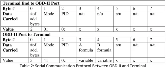
we sought a more direct communication approach. We were able to establish a hyper‐
terminal connection through a serial port with the following settings: 38400 baud, 8
data bits, no parity, xon/xoff flow control. The communication protocol for both the
send and receive side is given in Table 2. Low‐pass Filter ff k Subtract 14V DC Freq to Volt Converter Ex LM331; LM2917
Band Pass Filter
.8‐4 kHz A/D
converter Adapter
ESE 498 Senior Design Page 13
Terminal End to OBD-II Port
Byte # 0 1 2 3 4 5 6 7 Data Carried #of add. bytes
Mode PID n/u n/u n/u n/u n/u
Value 2 01 0c x x x x x
OBD-II Port to Terminal
Byte # 0 1 2 3 4 5 6 7 Data Carried #of add. bytes Mode PID A formula B formula
n/u n/u n/u
Value 3 41 0c variable variable x x x
Table 2: Serial Communication Protocol Between OBD‐II and Terminal
For example, sending the string 0x010c specifies the fetch current mode (0x01)
and the parameter identification number (PID) for RPM (0x0c). The return value is a 4
digit hex number. Because the resolution of the OBD measurement is of .25 RPM, the
return value corresponds to four times the instantaneous RPM. A return value of 0x1770
corresponds to the decimal value 6000 and an RPM of 1500.
Sound Synthesis
Assuming there is a digital signal provided that gives the RPM readout of a car;
there is the task of creating a new sound to overlap the current sound of the car. We
had to find audio clips of engine sounds to other cars. However, in order to provide a
realistic experience the sound needed to be a full range sound, meaning that the sound
must encompass the car’s startup, up shifts, and downshifts.
After we found a car engine sound, we separated the sound into each gear and
ESE 498 Senior Design Page 14
match. To prevent the sound from being choppy when the car is accelerating, the right
number of audio clips had to be taken. When all this came together, the synchronization
of the new car engine sound with the RPM input signal would create a new driving
experience.
Criteria:
The sound synthesis of the project had several criteria because reproducing the
harmonious sound of a super car was the entire basis of our project. The greatest
challenge with sound synthesis was producing smooth and continuous sound. Testing
had to be done to find the right number of sound clips so that all RPM could be
synchronized, while creating a smooth and uninterrupted sound. Secondly, there could
not be a large number of sound clips otherwise it would take too much memory to store
as well as processing power to synchronize.
Design Choices
Due to issues with consistency and stability we chose to pursue using the ODB‐II
connector for reading out RPM. The cigarette lighter did provide useable results,
however modern cars aim to filter out the noise in which we needed for the project.
Therefore, depending on the model of the car, the car’s wiring, as well as the battery
connections, results would vary. For these reasons the OBD‐II connector was the
ESE 498 Senior Design Page 15
The OBD‐II connector was capable of reading out RPM values as hex‐values
which in‐turn were used in correction with several sound files to piece together the
sound of a high performance engine. Our research trials showed that synthesizing the
sounds of a vehicle’s acceleration was markedly more difficult than for a steady speed.
When a vehicle accelerates there are many sound variations within each gear. Also the
sound of acceleration in different gears differs as well. When the car is idling in a steady‐
state however, only one or two sound files are necessary to replicate the sound.
During accelerations through the gears, several sound clips needed to be pieced
together to reproduce an accurate and clear sound. It was found that approximately 12
sound clips were necessary to reproduce a clean sound. The 12 audio clips were taken at
every 500 RPM intervals. 12 clips were necessary because in general cars idle at about
0.5‐1.0k RPM, and usually have redline limits at approximately 7k RPM. Therefore,
beginning at 1k RPM and taking sounds clips at every half interval provided a clean
sound throughout the acceleration of any given gear. If the sound were split into 24
clips the sound would be slightly better, but not significant enough to warrant the extra
complications associated with additional audio files.
Sound files were taken from BMW because their website provided a full range of
sound for several of their vehicles. Using the sound clips provided
from www.bmwusa.com we used audio editing software called Audacity. Audacity
allowed us to trim the sound files into individual gears and RPM.
ESE 498 Senior Design Page 16
Memory
The 12 sound files amounted to approximately 400kb of memory, therefore
there should be no problems storing the audio files in a practical application. Our device
would need a flash memory module built in with no more than 1GB of memory to be
able to store several audio clips from various vehicles. Given the low cost of flash
memory chips, especially ones that are only 1GB in capacity, memory costs should not
be an issue.
Audio Output
Delivering the audio clips to the car would be accomplished via several methods.
For our design we examined several possibilities including using an FM‐tuner, line‐in
auxiliary cable, or have a built in speaker. While a built in speaker would probably be the
simplest application for the user, it would not provide the best auditory experience. For
our final design we agreed upon using a FM‐tuner because the vast majority of vehicles
on the road today have at least an AM/FM radio. However, not all cars on the road
today have an auxiliary input port built in. The downside to using an FM‐tuner is that the
sound quality is only average and it requires an additional setup step for users.
However, an FM‐tuner would provide the best balance between sound quality and
universality among cars.
ESE 498 Senior Design Page 17
Ethical and Safety Concerns
Engineers are always faced with ethical decisions and concerns whenever they
design or build something that is meant to affect numbers of people. Our plug‐and‐play
engine sound replicator is no exception in that there are several ethical decisions and
concerns.
The first ethnical concern related to our project is our car engine sounds from
several different manufacturers. For the purpose of this project, I downloaded BMW
sound files from their website without seeking extensive legal consent. BMW may have
no issues either with our use of the sound files for research purposes. However, once a
product is developed and intended for sale, there could be legal licensing and trademark
issues involved. A car’s engine sound is just as unique as its body style and performance,
therefore proper licensing would need to be sought out in order for us to use different
car engine sounds in our final product.
Legal concerns are one side of ethical concerns related to our design project;
however there are safety concerns as well. The OBD‐II connector port on a car is a
diagnosis port with the ability to monitor and edit many car values and functions.
Improper use or untrained individuals could create problems with the electrical systems
in a car such as: air‐bag deployment, engine software, braking systems, and cruise
control systems. Our device would need to be designed to prevent users from being
able to access or change vehicle values both intentionally and unintentionally for their
ESE 498 Senior Design Page 18
A further concern with the OBD‐II connection is that it is a diagnosis port, and
not a standard input/output port designed for extensive use. Our device would put
tremendous strain on a port that was designed primarily to take diagnostic read outs.
While this has not yet been proven to be a safety issue in terms of reliability, it is still a
factor that must be taken into consideration.
On the safety side, the OBD‐II port us usually located on the steering column
where the driver’s legs may become entangled with the cord, as was experienced during
experimentation. For this system to be safe, we would have to devise a way of securing
the cord away from the driver’s feet.
One final ethical concern that must be taken into consideration is the fact that
producing any type of audio sound whether it is music or engines sounds; will distract
drivers in some form or another. There are groups who argue against the use of cell
phones and listening to music in cars because they pose a degree of danger. Creating
engine sounds of performance vehicles may enrich ones driving pleasure; however it
ESE 498 Senior Design Page 19
Future Considerations
In the future, there are several ways this project could be expanded upon. There
are areas of simplicity that could be further developed. Currently our model requires
some sort of portable laptop to read in RPM values as well as synchnoize sound files.
Needing a computer in the car is not very practical and in the future we could improve
upon the project by integrating some form of processing unit into the device. Using the OBD‐II connector to read out RPM values requires a cable to be
running from underneath the steering column across the car. Also the device requires to
be plugged into the cigarette lighter for power. In the future, we could explore the use
of wireless technology to remove the OBD‐II cable running across the vehicle. Also,
research could be done in implementing a battery in our device that way it would not
need to be plugged in. Because our project is still in its preliminary design stages, many
fine details had to be over looked. In the future we would work to address all the tiny
details and improve the ease of use for the customer.
Conclusions
Our goal with this project was to create a product to bring super car engine
sounds to everyday cars. Using an OBD‐II connector and properly edited sound files,
people can experience driving a super car for a fraction of the cost. The main costs of
our design would be the OBD‐II cable, a processing chip, and memory for the sound
ESE 498 Senior Design Page 20
would be required to mechanically replace one’s engine exhaust at an automobile repair
shop.
There are still legal and ethical issues which need to be addressed, however even
with these set‐backs there is a great potential in our product being successful. From an
engineering perspective, we were able to get our model working smoothly and
consistently. Given a greater amount of time to fine‐tune and perfect our model, it
would not be difficult to produce a product that would be easy to use and relatively
ESE 498 Senior Design Page 21
References
Audacity
http://audacity.sourceforge.net/
Open source software for recording and editing sounds
BMW of North America
http://www.bmw.com/com/en/insights/explore/bmw_magazine/2005/bmw_so unds/sounds.html
Whether smoothly idling or accelerating to top speed: every BMW engine has its
own signature sound, and this site provided the sound files used for our project
Elm Electronics. ELM327 User Guide and Specifications
www.elmelectronics.com
The cable we used had the ELM327 chip installed, and the specification for the
chip was included in the software bundle. This was used to set up a
HyperTerminal connection to the OBD‐II port and for to understand
communication with the OBD‐II port
OBD‐Codes.com.
http://www.obd‐codes.com/
This site was used to learn the query code for RPM and to understand the reply.