SPACECRAFT AREA NETWORK (SCAN) FOR PLUG
AND PLAY OF DEVICES
Pestana Conference Centre – Funchal, Madeira - Portugal
31 May – 4 June 2010 Sergio Montenegro, Benjamin Vogel DLR-RY Robert-Hooke-Str 7 23359 Bremen, Germany [email protected], [email protected] Vladimir Petrovic, Gunter Schoof IHP GmbH Im Technologiepark 25 15236 Frankfurt (Oder), Germany
[email protected] [email protected]
Andreas Herrholz Kim Gruettner
OFFIS
R&D Division Transportation Escherweg 2 - 26121 Oldenburg -
Germany
[email protected] [email protected]
ABSTRACT
By the definition of an (four our systems) “Standard” spacecraft area network (SCAN) we target three of the greatest problems we face with the avionics development of every new spacecraft are: 1. The huge cost and long development time due just to the interfaces specification: Our strategy is what we call network centric computing. We aim to create a spacecraft area network (SCAN) to which all devices and computers are attached. We aim to create a high speed interconnection link definition, which is so simple that it can be implemented and used by each and every one. We have already reference implementations which may be distributed as open source for both: FPGA IP cores and software Middleware.
2. The extremely high costs and almost no post-development reuse of the board computer. The reason for such arm reuse possibilities, is that normally IO devices are attached directly to the computer and each mission have different IO devices. In our concept, the board computer will not have any devices attached to it (it performs just computing and storage functions) therefore the same computer may be used in many different missions which have different device configurations and different IO Devices. All devices are truly network devices and are attached only to the
network.
3. ITAR restrictions and low performance of European space-qualified hardware: We create dependability using non dependable COTS components attached to our dependable network. Such COTS components have no ITAR restrictions and an order-of-magnitude higher performance than space-qualified ones. The only radiation-qualified and dependable component is the network and it is built in Europe.
Besides solving the main problems, we get a very high performance low cost core-avionics system. Its distributed character allows distributed development. It has a very high adaptability and
flexibility. Tasks may be migrated from one computing node to another in order to balance the load and to compensate failures.
We use the same communication protocol for software applications, for the network and for the devices. All communications in the system are based on the publisher/subscriber protocol (in software and in hardware). Publishers make messages public under a given topic. Subscribers (zero, one or more) to a given topic get all messages which are published under this topic. To establish a transfer path, both the publisher and the subscriber must share the same topic. A topic is represented by a topic ID and a data type.
consumers (subscribers). This does not depend on if the services are produced by software components or by hardware components. The same applies to the consumer of services.
The network is based on a publisher/subscriber protocol which is implemented our open source RODOS operating system, as a software middleware for the software tasks and in a FPGA as a middleware switch for hardware devices and to interconnect computing nodes. An ASIC implementation of the network is in work.
The central component of our network centric concept is the network which is the heart of the system. If it fails, the system fails. Therefore to create a dependable network we use redundant robust components, with ultra fast recovery time. The building block of the network is the middleware switch, which logical view is way very similar to a software middleware.
The middlware siwtch is being implemented as a radiation hard ASIC from IHP and at the same time OFFIS crates a system-C model of its functionality to be able to validate our concepts by means of high level simulation, before the chip is created. The models will be distributed as open source to facilitate the use of the SCAN concepts for new users. The high level simulation is used primary to validate algorithms and to estimate routing performance. Beside this, the model is used to simulate anomalies, overloading, messages corruptions etc. in order to validate our fault tolerance concepts.
The Middleware Switch, through hierarchical view has three main modular groups: communication ports, communication links and a central processing unit (LEON-2 CPU). Communication ports are connected via the switch matrix or DMA channels. The DMA channels are configured to transfer the data between ports and main memory. The switch matrix may be used to forward high speed messages directly between ports using a multi cast protocol. The internal CPU may communicate with every port, to the switch matrix and to DMA controller to monitor and control their
configuration, the data traffic and flow control.
The Middleware ASIC will be developed in SGB25V - 0.25µm IHP BiCMOS technology. Several radiation tests have shown the radiation immunity of this technology. As a consequence, the IHP is going now the next step to get a ESA qualified process for space products which should be reached in 2010. To increase the radiation immunity even more, IHP is working on new design techniques for SEL (Single Event Latch-up) and SEU (Single Event Upset) tolerant designs.
1. MOTIVATION
Three of the greatest problems we face with the avionics development of every new spacecraft are: 1. The huge cost and long development time due just to the interfaces specification (IDC =
Interface control Document) which has to be written and specified for every satellite from scratch. This consumes at least one working year and many individual years.
2. The extremely high costs and almost no post-development reuse of the board computer. This is due to the fact that all devices are attached to the computer and the device configuration is different for almost every satellite. This implies a required redesign of the board computer for every new spacecraft.
3. ITAR restrictions - USA export restrictions for space qualified components (and sometimes for software too) - and low performance of European space-qualified hardware.
With the definition of our Spacecraft Area Network (SCAN) we target these three main problems and many other “minor” inconvenient factors which we face in every avionics development.
(SCAN) to which all devices and computers are attached. We aim to create a high speed
interconnection link definition, which is so simple that it can be implemented and used by each and every one. We have already reference implementations which may be distributed as open source for both: FPGA IP cores and software Middleware.
The network switch will be developed in Europe as ASIC. This ASIC will be distributed at
production cost, with some supporting hardware. We aim to create a community (e.g. an opensource community for the development of the operating system) to use and further develop the network centric approach.
2. SOFTWARE PROTOCOL AND HARDWARE NETWORK
Our interconnection link defines a very simple message distribution protocol. Each message in the network receives a topic tag which identifies its content and purpose. Examples of topics could be: position, temperature, and attitude. Services will be published as topics regardless of whether they are produced by software tasks or by hardware devices. Any application or device may subscribe to the topics which it needs to help to produce its services.We have already implemented a very simple software building blocks execution platform to support this concept. It includes a middleware which operates with the publisher/subscriber protocol.
Publishers make messages public under a given topic. Subscribers (zero, one or more) to a given topic receive all messages which are published under this topic. To establish a transfer path, both the publisher and the subscriber must share the same topic. A topic is represented by a topic identifier (ID) and a data type.
This method will be used to interconnect service providers and consumers. In order to be able to attach COTS (Commercial Off The Shelf) devices (with their own protocols) to the network, the network will provide the required interfaces and protocol converters. The COTS devices receive and send their own messages, and then the protocol converters translate them into our internal “universal language”. The network will perform all required transformations in order to make the message transport transparent.
The current FPGA implementation of the network may support different protocols. The next generation (being building now) will be based on an ASIC switch, which can support only two different physical links: our own high speed “Simple Synchronous Serial Protocol” (S3P) and a simple UARTS. To access other low level protocols (e.g. CAN, SPI, I2C, SpaceWire) we aim to develop bridges and remote terminal controllers (RTU). In FPGA implementations such bridges and converters may be implemented in the same chip just like with the network. The ASIC cannot support as many different protocols, however. In any case the bridges and RTUS will be transparent for the message distribution.
3. CURRENT DEVELOPMENT
The targets of our current activities are:
- high speed serial interfaces (50 to 200 MBit/sec)
- network switch as submicron ASIC for 32 Ports (0.25 micron and 0.13 for the next step) - bridges and RTUs for COTS devices
- a high speed (200 MIPS) board computer based on FPGAs
- building blocks execution platform software, including a middleware - satellite management software and
Some of these technologies are already implemented.
The first version of the ASIC network switch (0.25 micrometer technology) will be ready by 2010. It will be radiation resistant and latch-up immune. We plan a further development based on 0.13 micron technology to include redundancy for fault tolerance. The software will provide redundancy and fault-tolerance management.
4. EXPERINCE FROM FORMER PROJECTS
Or concepts are based on our experience from former satellites we have build and from new spacecrafts which are being developed now.
BIRD is a German small satellite. It was built to observe terrestrial fires via infrared spectroscopy and was launched in 2001. TET is similar to BIRD in design and its mission is to validate new space technologies. The launch of the TET satellite is scheduled to take place in 2010. In both cases the central element in their architecture is the board computer which has to provide computing power, storage (mass memory), input/output interfaces for many (> 20) data buses and devices. The central element has to be dependable and robust. It has to manage the redundancy and, additionally, it has to execute its real-time job. Therefore such a computer system becomes very complex,
expensive and susceptible and is not reusable in different missions with different input/output devices. Even TET’s similarity to BIRD required a new development of the board computer, because a few of the devices needed to be substituted.
The BIRD and TET main computers were implemented using four computers. BIRD is totally based in COTS technology, TET has both Rad-Hard and COTS. One of the 4 nodes (the so called worker node) controls the satellite, while a second node (monitor node) monitors the correct operation of the worker node. In case the worker fails, the monitor takes over the job of the worker while the crashed node performs a recovery cycle.
Two other node computers are spare components and are disconnected. In case of a permanent failure of one running computers, the spare computer pair will be used instead of the failed pair. Both BIRD and TET are only a small step beyond state of the art. They have more redundancy than is normal because they are based on COTS (not space-qualified) components. The redundancy management is performed in software. A lot of functionality which normally is implemented in hardware, in BIRD and TET is implemented in software and takes advantage from the higher redundancy and redundancy management.
Our Network Centric Concept is based on our experiences with BIRD and TET. We saw what to improve to get a faster development, to get higher reuse, and to get higher dependability and performance at lower cost.
5. TECHNICAL IMPLEMENTATION
We are currently developing, for a series of satellites, a high performance generic board computer (called SSMMU) based on FPGAs. These board computers may be used to control the satellite and at the same time to process and store the payload data, but the central element will not be the computer any more, but the network, which can interconnect many buses and devices, including computers and mass memory devices. In this architecture the computer is not a central element, therefore it may be very simple, cheaper and have lower dependability requirements.
The entire functionality of the avionic system will be obtained by plugging hardware and software components together. Each of these components shall be replaceable without having to modify the
rest of the system. To guarantee dependability, the only component which shall be dependable is the network. Our technology research is concentrated on the network which will include intrinsic redundancy and will be built using European radiation-resistant components. The redundancy management will again be executed through software.
The Network Centric approach provides much higher dependability, flexibility, scalability and performance. The current implementation of the network relies on commercial high-capacity
reprogrammable gate arrays (FPGAs). We are currently developing, together with a microelectronic partner IHP (Innovations for High Performance Microelectronics,
http://www.ihp-microelectronics.com), a 32-Ports middleware Switch ASIC using their submicron radiation tolerant technology (0.25 micron). 16 of such ports are simple UARTS and 16 implement our high speed simple serial link S3P. The next generation will be based on 0,13 Micron technology and will be able to handle up to 32 full duplex data links, 16 of them high speed links with up to 200
Mbits/second each. This means more than 6.4 Gbits/second throughout the network. DLR has implemented the RODOS (Realtime Onboard Dependable Operating System,
http://www.dlr.de/rodos) execution platform, which may also be used as a standalone real-time operating system. RODOS includes a middleware which is compatible with the network messages, so allowing a smooth integration and mixing of services provided by both software and hardware. RODOS is already available free as an open source project.
All communications in the system are based on the publisher/subscriber protocol.
Reminder: Publishers make messages public under a given topic. Subscribers (zero, one or more) to a given topic get all messages which are published under this topic. To establish a transfer path, both the publisher and the subscriber must share the same topic. A topic is represented by a topic ID and a data type.
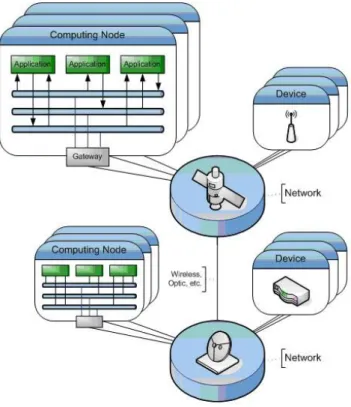
On the software side the middleware implements an array of topics which may be compared to hardware buses. Each time a message is published under a given topic, the middleware checks for all subscribers that wish to receive it. Each one will receive a copy of its content. To go beyond the limits of the computing node we use gateways which may read all topics and forward them to the network and vice versa (Figure 1)
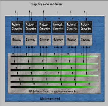
The building block of the network is the middleware switch, which logical view is way very similar to the software middleware (figure 2).
Figure 2: Logical view of the Middleware Switch (not the hardware implementation view) The middleware switch implements (using internal software) an array of gateways connected to an array of virtual topic buses. In the hardware there is a switch matrix to interconnect port instead of an array of topics (see next chapter). The gateways distribute locally all incoming messages, whereas all other gateways select the messages which they will then forward, convert them to the corresponding protocol and send them using the associated link. It makes no difference what we find on the other side of the link, whether it is another network, a node computer, a device or a bus for devices.
6. MIDDLEWARE SWITCH ASIC
The Middleware Switch, through hierarchical view has three main modular groups: communication ports, communication links and a central processing unit (CPU). Communication ports are
connected via the switch matrix or DMA channels. The DMA channels are configured to transfer the data between ports and main memory. The switch matrix is controlled by the CPU – in this case Leon 2 processor – in real-time and may be used to connect high speed ports directly to each other. Furthermore one link of the switch matrix is connected to a DMA channel to allow the traffic to the memory. The CPU may communicate with every port, the switch matrix and DMA controller to monitor and control their configuration, the data traffic and flow control. The Processor reads the topic ID directly from a message and after processing in software, gives a corresponding instruction to the switch matrix. The first ASIC implementation consists of 16 high speed S3P - simple
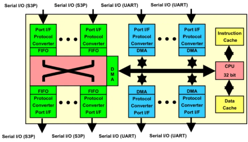
synchronous serial - ports, 16 UART ports, Leon 2 core processor and switch matrix (figure 3). Further implemented functions are a debug unit, programmable timers, pulse generators and counters as well as built-in-self-test (BIST) features.
Figure 3. Basic concept of the Middleware Switch ASIC
In architecture development process, we agreed to have two different port connecting systems. For S3P ports we are using a switch matrix, which basically consists of multiplexers. Transfer data are buffered in FIFO buffers, which are implemented together with ports. For UART ports we are using DMA controllers and the AHB processor bus to transfer data between ports and external memory (not shown in fig. 3). All messages which are stored in the memory may be manipulated by the CPU before the transmission to any destination device.
The Middleware Switch uses a uniform internal protocol to allow simple switchable connections between very heterogeneous devices. Therefore all ports are using protocol converters to convert between external used protocols and the internal format. To allow different device types to be connected to the same port pin the protocol converters must be configurable. The most important configurations are related to message framing, flow control, synchronization and header
information (topic ID, message length). If any new protocol format is not yet implemented in the port hardware the message must be transferred into the memory and the CPU can do the protocol conversion. Therefore the implemented concept is very flexible and even cascading several ASICs is possible.
The Middleware ASIC implementation uses integrated hardware handshaking but supports also handshaking by software. Because of different communication protocols even software
handshaking must be recognized and handled by the port logic. As a result devices can send and receive flow control commands via the Middleware Switch to avoid data losses and
re-transmissions. Such commands (Stop, Continue) can be transmitted anytime within or between messages. This is very useful and necessary when devices communicate with different speed to each other and the internal buffers are running out of memory space..
The presented ASIC implementation of a Middleware Switch uses Leon 2 IP core from Aeroflex Gaisler© (formerly Gaisler Research) as the processor unit; the DMA core from Synopsys© Design Ware library; and all other components (memories, FIFOs, EDAC, ports and all control logic) from IHP GmbH.
The error detection and correction (EDAC) module is used to protect the data written into memory. The EDAC algorithm is based on Hsiao coding scheme and provides one bit error correction and two bits error detection. Registers, flipflops and latches should be protected through TMR (Triple Modular Redundancy) or DMR (Double Modular Redundancy) which we will implement in a future design.
The Middleware ASIC will be developed in SGB25V - 0.25µm IHP BiCMOS technology. Several radiation tests have shown the radiation immunity of this technology. As a consequence, the IHP is
CPU 32 bit Instruction Cache Data Cache Serial I/O (S3P) Serial I/O (S3P) Serial I/O (UART) Serial I/O (UART)
Serial I/O (S3P) Serial I/O (S3P) Serial I/O (UART) Serial I/O (UART) Port I/F Protocol Converter FIFO Port I/F Protocol Converter FIFO FIFO Protocol Converter Port I/F FIFO Protocol Converter Port I/F Port I/F Protocol Converter DMA Port I/F Protocol Converter DMA DMA Protocol Converter Port I/F DMA Protocol Converter Port I/F D M A
going now the next step to get a ESA qualified process for space products which should be reached in 2010. Therefore the IHP could become an important European supplier for space qualified ASICs contributing to more ITAR-free products in Europe.
To increase the radiation immunity even more, IHP is working on new design techniques for SEL (Single Event Latch-up) and SEU (Single Event Upset) tolerant designs. The main goal is to
develop radiation tolerant designs for space applications without wasting much chip area and power consumption. The improved design technique should accept SEU and SEL effects, which could not be avoided by technological means, and correct them in background without affecting the real-time behavior of the running system.
Further versions of the Middleware Switch ASIC should comprise a full fault-tolerant design. In parallel first activities will be started to get more information about radiation immunity of the IHP 130nm technology.
7. HIGH LEVEL MODELING OF THE NETWORK
To support the specification and development of the ASIC implementation a configurable high level model of the Middleware Switch has been developed. The model abstracts from many of the details of the ASIC design but still reflects the correct functional and timing behaviour of the switch. The model has been developed using the C++ based system-level modelling language SystemC which is available under an open-source license including a free reference implementation.
Initial motivation for the SystemC model was to allow early exploration of different architecture options for the ASIC to find an acceptable balance between costs, dependability, flexibilty and performance of the ASIC. For instance, larger FIFO buffers can compensate more variations of data bandwidth and latency of connected devices but also have significant impact on the area costs of the chip. Similarly more complex routing and scheduling algorithms may serve for a better balanced and fair distribution of the available bandwidth but may also require a faster and therefore larger and more costly controller within the switch.
Due to the modularity and configurability of the switch model all of these different architectural parameters can be modified to generate different implementation variants of the switch. These variants can either be tested by simulation in smaller application scenarios using traffic generators and error injectors but may also be integrated into larger network models simulating different topologies and architectures with multiple switches and network nodes. Also the software controllable features of the switch like routing, scheduling and flow control can be tested and modified during simulation runtime.
In future, it is planned to extend the SystemC simulation model to a virtual prototyping environment combining the SystemC simulation of the network and hardware components with the RODOS execution platform. This will allow designers of SCAN systems based on our approach to create functional and timing accurate virtual prototypes of complex avionics systems. Using these models the influence of the network on the timing and functionality of the overall system can be simulated and evaluated long time before the final hardware is available. Moreover the system architecture of computation nodes, sensors, actors and the network can be varied very easily enabling the exploration of trade-offs between redundancy, dependability, performance and cost of the whole system.
As part of the strategy to create an community around the set of software and hardware IP for the SCAN it is planned to release the virtual prototyping environment also as open-source to provide a free and extendible development platform for design and simulation of SCAN-based systems.
8. SUMMARY
Our response to the three main problems mentioned before is: Problem 1: Many different ICDs to specify.
Solution 1: We create a standard plug and play interface. Problem 2: Almost no reuse of board computer.
Solution 2: The board computer will not have any devices attached to it (it performs just computing and storage functions) therefore the same computer may be used in many different missions which have different device configurations.
Problem 3: ITAR restrictions and low performance space qualified devices -
Solution 3: We create dependability using non dependable components attached to our dependable network. Such COTS components have no ITAR restrictions and an order-of-magnitude higher performance than space-qualified ones. The only radiation-qualified and dependable component is the network and it is built in Europe.
Besides solving the main problems, we get a very high performance low cost core-avionics system. Its distributed character allows distributed development. It has a very high adaptability and
flexibility. Tasks may be migrated from one computing node to another in order to balance the load and to compensate failures.
9. REFERENCES
[1] Bärwald W. and Montenegro S., BIRD-Spacecraft bus controller, Small Satellites for Earth Observation, Vol. 3, 371-373, 2001
[2] Sergio Montenegro, Jan-Thimo Grundmann, Bobby Kazeminejad, Peter Spietz, The new DLR Standard Satellite Bus series (SSB), Small Satellites Systems and Services - The 4S Symposium, German Aerospace Center, 2008
[3] Mottola, S., Börner, A., Grundmann, J.T. , Hahn, G., Kazeminejad B., Kührt, E., Michaelis, H., Montenegro, S., Schmitz, N., Spietz P.: AsteroidFinder: Unveiling the Population of Inner Earth Objects, 59th International aeronautical congress, 29th September to 3rd October 2008, Glasgow, Scotland.
[4] BIRD (Bispectral InfraRed-Detector
http://www.dlr.de/rb/en/desktopdefault.aspx/tabid-2731/6724_read-6311 [5] TET Technology Experiments Carrier
http://www.dlr.de/rd/en/desktopdefault.aspx/tabid-2274/3396_read-5085
[6] Schoof, G., Kraemer, R., Jagdhold, U. Wolf, C., Fault-tolerant Design for Applications Exposed to Radiation, Proceedings of the Conference DASIA 2007 - Data Systems in Aerospace, 2007.