Connecting People to Business
System Setup Guide
Version 6.X
OnviSource, Inc.
Headquarters:
1255 West 15th Street, Suite 500 Plano, TX 75075 Main: 469.241.9200 Fax: 469.241.0247
Operations:
2300 North 10th Street Enid, OK 73701 Main: 580.242.4636 Fax: 580.242.8255
OnviCord System Setup Guide 2 Revised 3/13/2009
Table of Contents
Table of Contents ... 2
Getting Started... ... 4
Common Sense Wiring... 6
Network Considerations... 7
Determining Your Digital Telephone Type ... 8
Maximum T1/E1 Parrot Tap Distance... 9
Determining Your Hardware Type... 10
Installation: Wiring Hardware ... 13
Assigned Seating User/Channel Form... 14
Free Agent Seating Station/Label Form... 16
Verify OnviCord Pro Block Connections ... 17
Installation: Analog/Digital System ... 19
Integrating the OnviCord Pro to Your Existing Wiring ... 21
Installation: Parrot T1/E1... 28
Installation :VoIP... 30
Integrating OnviCord Pro with Existing VoIP Phone Systems... 30
Installation : Client Software ... 36
Windows Terminal Server Environment... 39
Setup Confirmation ... 40
SDK ... 46
Integrating with your software... 46
Feature Highlights: Client Applications ... 47
Overview: OnviCord Web ... 47
Overview: OnViews(including OnviCord Monitor) ... 47
Overview: OnviCord Agent ... 47
Authentication for OnviCord Web Access... 49
Establishing a Secure Sockets Layer (SSL)... 50
Determining your SMTP Server ... 51
Configuring the Local SMTP Service ... 53
Verify SMTP Service Installation ... 53
Changing the OnviCord Pro Computer Name ... 56
Performing Preventative Maintenance ... 57
Defrag... 57
Wiring Diagrams... 58
2-Wire Digital/Analog 66 Block ... 59
2-Wire Digital/Analog 110 Block ... 60
Handset Connections ... 61
Radio/Powered Analog Source ... 62
Analog/Centrex Tap ... 63
Digital Hybrid ... 64
BRI Two Phones... 66
Lucent Legend/Merlin Magix MLX 4-Wire Tap ... 67
Lucent Index/Mitel Serial Wiring ... 68
Cybertech Parrot T1/E1... 69
VoIP ... 70
Revision History ... 71
Getting Started...
OnviCord System Setup Guide 4 Revised 3/13/2009
Getting Started
Getting Started
Getting Started
Getting Started...
..
..
..
Follow these instructions in the order given to properly set up your
OnviCordsystem. If you have questions about the installation or operation of this product, telephone an OnviSource technician at 1-800-311-3194 between 8:00 A.M. and 5:00 P.M. CST.
Before proceeding, refer to the System Requirements section on the
OnviCord CD to verify what operating systems we support.
Depending on your operating system, the images shown in this document may be slightly different from what you see. Your box (CPU) may also be different from the ones shown in this document.
Please see www.onvisource.com for approved Microsoft update lists and or requirements.
IMPORTANT: Regular back up procedures enable you to quickly recover data after a power failure or other serious incident and allows you to permanently store data after your system reaches storage capacity. We strongly encourage you to evaluate your
organization’s backup and recovery needs to determine what tools and procedures to implement at your organization. After
completing the steps in this guide and before placing your system in operation, backup your system database.
NOTE: For consistent and accurate results when changing the licensing on an OnviCord system (3.0 and greater), you will need to restart the following: Worldwide Web Publishing Service, data service, all recording services.
When tapping a digital phone, refer to the Telephony Support List in the Install Documents section of the OnviCord CD. Find your phone type on the list. If you are unsure about your switch type, contact your telephone system vendor. If you do not see your system listed, contact OnviSource Technical Support before continuing. Attempting to connect an
unsupported phone type can cause permanent damage to your
Getting Started...
Windows, Microsoft, CyberTech and other products and manufacturers listed in this document are trademarks of the respective companies.
Getting Started...
OnviCord System Setup Guide 6 Revised 3/13/2009
Common
Common
Common
Common Sense Wiring
Sense Wiring
Sense Wiring
Sense Wiring
Failure to follow these recommendations can cause unsatisfactory performance on your system (i.e., interference and/or static in line, dropped calls, etc.).
• Do NOT run telephone wiring next to power lines. We recommend
at least 3 feet of separation between phone lines and power lines.
• Do NOT locate telephone and electrical receptacles (plug-ins) at
the same location on the wall. We recommend at least 3 feet of separation between the two.
• Do NOT coil a telephone line and lay it behind a monitor. • Do NOT bundle power cords with amphenol cables or phone
cables.
• Do NOT punch down when switch is on.
• Do NOT run phone lines over fluorescent lighting in ceiling.
VoIP customers:Do NOTuse a HUB to achieve port mirroring of VoIP traffic.
IMPORTANT: Place the recording server at least 6 feet away from your switch or other source of electromagnetic interference.
Place your system server(s) in an environment that is free of dust, smoke, humidity, excessive vibration, magnets, and static electricity. Avoid temperature extremes and provide adequate ventilation. We recommend using a UPS (uninterrupted power supply) for your server(s).
Never place covers and/or other objects on server cases.
Getting Started...
Netw
Netw
Netw
Network Considerations
ork Considerations
ork Considerations
ork Considerations
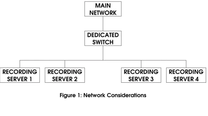
If your network has more than one recording server, we recommend a using dedicated switch for communications between the OnviCord
servers.
MAIN
NETWORK
DEDICATED
SWITCH
RECORDING
SERVER 1
RECORDING
SERVER 2
RECORDING
SERVER 3
RECORDING
SERVER 4
Figure 1: Network Considerations
IMPORTANT: Using Device Manager, select your Network Adapter and right-click to view Properties. On the Advanced tab, use the drop-down box to set the appropriate value.
Getting Started...
OnviCord System Setup Guide 8 Revised 3/13/2009
Determining Your Digital Telephone Type
Determining Your Digital Telephone Type
Determining Your Digital Telephone Type
Determining Your Digital Telephone Type
When tapping a digital phone, refer to the Telephony Support Listin the Install Documentssection of the OnviCord CD. Find your phone type on the list. If you are unsure about your switch type, contact your telephone system vendor. If you do not see your system listed, contact the One Call Solution Center before continuing. Attempting to connect an
unsupported phone type can cause permanent damage to your
OnviCord system.
For T1/E1 systems, refer to Maximum orT1/E1 Parrot Tap Distance on page
10, whichever is appropriate.
Maximum T1/E1 Parrot Tap Distance
Maximum T1/E1 Parrot Tap Distance
Maximum T1/E1 Parrot Tap Distance
Maximum T1/E1 Parrot Tap Distance
Maximum T1/E1 Parrot Tap Distance
You MUST use the one foot (1’) amphenol cable that accompanies your shipment. It may not be replaced with a longer one. Otherwise, your system will not work.
OnviCord System Setup Guide 10 Revised 3/13/2009
Determining Your Hardware Type
Determining Your Hardware Type
Determining Your Hardware Type
Determining Your Hardware Type
IMPORTANT NOTE:Unpack all items received, but do NOT attempt to connect system(s) to your telephone service until instructed to do so.
This document contains instructions for single and multi-box configurations. If yours is a single box (tower) configuration, plug in the computer
peripherals (mouse, keyboard, and monitor) and power up the system. If you received more than one box (tower), locate the one labeled
Recording Server. Plug in the peripherals and power up that system.
From your desktop, select Start->Programs->OnviSource->License
Manager.
If you receive the below error while attempting to launch the
License Manager, you must shut down the Recording Service before continuing.
To do so, launch Start->Settings->Control Panel from your desktop. Double-click on Administrative Tools, then double-click Services. Scroll down the list until you find OnviCord Recording Service. Right-click and select Stop.
For those with Parrot configurations, place your cursor in an empty section on the task bar, right-click and select Task Manager. Select
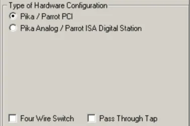
On the following line(s), write down the type(s) of hardware configuration selected in the upper left portion of the License Manager window. Your screen may look different than the one shown.Be sure to also note
whether or not the Four Wire Switch or Pass Through Tap box are checked.
Figure 3: Determine Hardware Configuration
Type of Hardware Configuration________________________________________ Type of Hardware Configuration________________________________________
Four Wire Switch? Y / N Pass Through Tap? Y / N
Write down the number of cards and channels from the Card and Channel Countsection.
Figure 4: Determine Card and Channel Count
Cards Channels
Parrot Digital H100 N/A OnviCord VoIP
Parrot T1/E1 Parrot Analog Parrot Digital
OnviCord System Setup Guide 12 Revised 3/13/2009
Click on the X in the upper right corner of the application to close the License Manager window. Power down the PC.
Repeat this procedure for eachbox labeled Recording Serverif you have more than one and write the information below. (Photocopy the form if necessary).
Type of Hardware Configuration________________________________________
Type of Hardware Configuration________________________________________
Four Wire Switch? Y / N Pass Through Tap? Y / N
Cards Channels
Parrot Digital H100 N/A OnviCord VoIP
Parrot T1/E1 Parrot Analog Parrot Digital
Type of Hardware Configuration________________________________________
Type of Hardware Configuration________________________________________
Four Wire Switch? Y / N Pass Through Tap? Y / N
Cards Channels
Parrot Digital H100 N/A OnviCord VoIP
Parrot T1/E1 Parrot Analog Parrot Digital
Installation: Wiring Hardware
Installation:
Installation:
Installation:
Installation: Wiring Hardware
Wiring Hardware
Wiring Hardware
Wiring Hardware
The card type(s) you wrote down in the previous step determine how you proceed. Using the chart below, find your card type from the column on the left. Turn to the appropriate set of instructions and complete the steps listed for your hardware configuration in the order given. You may have to follow more than one diagram and/or set of instructions if you have more than one card type in the same box.
Card Type Wiring Instructions
Parrot Analog Analog/Digital System Installation on page 19 Parrot Digital Analog/Digital System Installation on page 19 Parrot T1/E1 Parrot T1/E1 Installation on page 28
OnviCord VoIP VoIP Installation on page 30
Figure 5: Hardware Type/Wiring Diagram Reference
Note to installer:
As you connect the system to the telephone interface, you must fill out the following:
• Assigned Seating User/Channel Form on page 16 and/or the Free Agent Seating Station/Label Form on page 17
• You will need this information later in the setup process to configure
users/channels in OnviCord Web.
• VoIP only customers do NOT need to complete either form.
When finished wiring your system, continue with the instructions in the subsequent section for installing Adobe Acrobat Reader.
Assigned Seating User/Channel Form
OnviCord System Setup Guide 14 Revised 3/13/2009
Assigned
Assigned
Assigned
Assigned Seating User/Channel Form
Seating User/Channel Form
Seating User/Channel Form
Seating User/Channel Form
Photocopy this form if necessary. Fill out a form for each block (or patch panel) while wiring, noting on the form which channels you did nothook up. Fill out the last column when labeling channels.
NOTEEnter a channel ORstation number, but not both.
Block# Channel# Station# User Name Extension Label
Free Agent Seating Station/Label Form
OnviCord System Setup Guide 16 Revised 3/13/2009
Free Agent Seating Station/Label Form
Free Agent Seating Station/Label Form
Free Agent Seating Station/Label Form
Free Agent Seating Station/Label Form
Photocopy this form if necessary. Fill out a form for each block wiring, noting on the form which channels you did nothook up.
Block# Channel# Station# User Name Extension Label
Verify OnviCord Pro Block Connections
Verify
Verify
Verify
Verify OnviCord Pro
OnviCord Pro
OnviCord Pro
OnviCord Pro Block
Block
Block
Block Connections
Connections
Connections
Connections
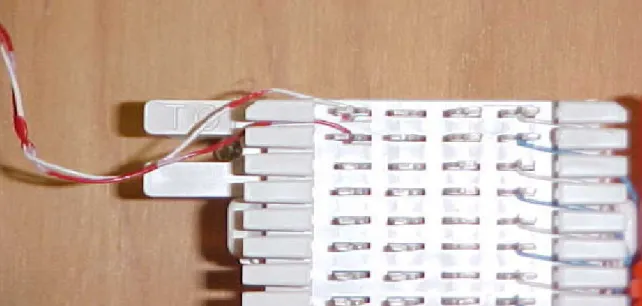
If your system installation kit contains an OnviCord Problock (shown), verify the connections on the block by following the procedure in this section. Failure to perform this step can result in channels not recovering from No Line, cards continually attempting to re-boot, and/or a loss of sync issues.
Verify OnviCord Pro Block Connections
OnviCord System Setup Guide 18 Revised 3/13/2009 Figure 6: Block Connections
Use the BLUNT end of the punch tool to re-punch the entire pre-wired side (right side).
Figure 7: Punch Tool
Installation: Analog/Digital System
Figure 8: Incorrect Punch Tool Use
Installation:
Installation:
Installation:
Installation: Analog/Digital System
Analog/Digital System
Analog/Digital System
Analog/Digital System
Read all instructionsin this section and reviewthe appropriate Wiring
Diagrams on page 53 before beginning. This section describes a 2-wire
installation only. If you have a 4-wire, refer to the diagramspertinent to your situation.
IMPORTANT: Place your system box(es) in an environment that is free of dust, smoke, humidity, excessive vibration, magnets, and static electricity.
Avoid temperature extremes and provide adequate ventilation. We recommend using a UPS (uninterrupted power supply) for your box(es).
Never place objects and/or covers on top of PC cases.
Failure to follow these recommendations may void your warranty!
Your OnviCord Pro installation kit includes: 1-Amphenol cable
Installation: Analog/Digital System
OnviCord System Setup Guide 20 Revised 3/13/2009
1-package bridge clips
Figure 9: Analog/Digital 2-Wire Installation Kit
You will also need:
Phillips and flat-head screwdriver(s) Cross-connect wire
Punch Tool
Two screws for block
Installation: Analog/Digital System
Integrating the
Integrating the
Integrating the
Integrating the OnviCord Pro
OnviCord Pro
OnviCord Pro
OnviCord Pro to Your Existing Wiring
to Your Existing Wiring
to Your Existing Wiring
to Your Existing Wiring
This section tells how to connect the OnviCord Proterminating block to the OnviCord Proserver and how to connect the lines on your existing telephone block to the OnviCord Pro terminating block.
Hook up the PC peripherals (mouse, keyboard, monitor, LAN, etc.) and power, but do not start the system yet.
Figure 11: Hook Up PC Peripherals
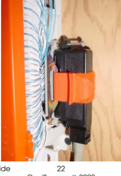
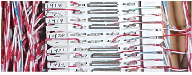
Locate your PBX box, which is usually in a closet or small room. You should see wires going from the PBX to a telephone block mounted on the wall, similar to the one shown.
Installation: Analog/Digital System
OnviCord System Setup Guide 22 Revised 3/13/2009 Figure 12: Typical Phone Block
Screw the OnviCord Proterminating block to the wall near your telephone block.
Figure 13: Install OnviCord Pro Terminating Block
Plug the 90oend of the Amphenol cable (provided) to the OnviCord Pro
Installation: Analog/Digital System
Figure 14: Terminating Block With Amphenol Cable Attached
Digital/analog combination systems use two connections on the back of your OnviCord Proserver. The photo below shows a digital (marked D) and analog (marked A) interface. T1/E1 systems are marked T1 or E1.
Figure 15: Connect Amphenol Cable to PC
WARNING
:
Connecting analog trunks to digital cards may permanently damage yourOnviCord Prosystem.Installation: Analog/Digital System
OnviCord System Setup Guide 24 Revised 3/13/2009
Marking certain that you are using the appropriate cable for each card (if there is more than one), connect the OnviCord Problock to the OnviCord Prorecording server by plugging the 180ºend of the cable into the back of the PC.
Figure 16: Connect Cable to PC
NOTE:Identify which phone lines on the block you want to record. Ideally, your block will be labeled with extension numbers. If your block is not labeled, you may need a toner to determine which lines go to the telephones you want to record.
Punch down the cross-connect wire on the right side of your existing phone block. (When punching down the wires, come in from the top and cut the wires on the bottom.) This assumes you are connecting a 2-wire system. If you are instead connecting a 4-wire system, refer to the appropriate Wiring Diagrams on page 53.
Installation: Analog/Digital System Punch down the left side of the OnviCord Pro block, leaving adequate wire length (approximately 1”) for modifications you may want to make at a later date. This assumes you are connecting a 2-wire system. If you are instead connecting a 4-wire system, refer to the appropriate Wiring
Diagrams on page 53.
Figure 18: Punch Down OnviCord Pro Block
Insert bridge clips (provided) on the OnviCord Problock.
Installation: Analog/Digital System
OnviCord System Setup Guide 26 Revised 3/13/2009
You may need bridge clips on the two center posts of your existing block to complete the connection.
Figure 20: Bridge Clips on Existing Telephone Block
Figure 21: Correct Punch Technique
Power up your system. With multiple boxes, start the data server first, followed by the recording server(s) and video server(s) if applicable.
NOTE: If you have Lucent Partner Switch and you experience recording
issues at the time of installation, you may need to adjust your voltage settings. From the interactive menu on the OnviCord Pro
CD, select Utilities and launch the CyberTech Maintenance Service.pdf file. Follow the instructions to run the utility. With the phone on hook, use the analog_stat command (-24, -48, etc.) and note the setting. Repeat the procedure with the phone off hook and note the setting. Now use the command analog_hook (ch_nr)(low)high ORanalog_hook on all. (Low=2 above OFF measurement; high=2 below ON measurement.)
Installation: Analog/Digital System Enter the appropriate minimum and maximum voltages for each line or for all lines.
Installation: Parrot T1/E1
OnviCord System Setup Guide 28 Revised 3/13/2009
Installation:
Installation:
Installation:
Installation: Parrot T1/E1
Parrot T1/E1
Parrot T1/E1
Parrot T1/E1
IMPORTANT: Place your system box(es) in an environment that is free of dust, smoke, humidity, excessive vibration, magnets, and static electricity.
Avoid temperature extremes and provide adequate ventilation. We recommend using a UPS (uninterrupted power supply) for your box(es).
Never place objects and/or covers on top of PC cases.
Failure to follow these recommendations may void your warranty!
We support the following protocols: T1 ISDN PRI, E1 ISDN PRI, E1 DASS2, E1 DPNSS, E1 QSIG, T1 VOX, E1 VOX and the following T1 CAS protocols: FXO/FXS D4 loop start, FXO/FXS ESF loop start, FXO/FXS D4 ground start, FXO/FXS ESF ground start, E&M wink start.
Your installation kit will include an RJ-45 splitter, a Multi-Jak adapter and an amphenol cable. You MUSTuse the one foot (1’) amphenol cable that accompanies your shipment. It may notbe replaced with a longer one. Otherwise, your system will notwork. Finish reading the instructions in this section, then refer to CyberTech Parrot T1/E1 on page 64.
Installation: Parrot T1/E1 Connect one end of the amphenol cable to the CyberTech/Parrot card (back of your box). Connect the other end of the cable to the back of the Multi-Jak adapter. Connect the Y-splitter to Multi-Jak adapter ports 1, 3 or 5 for each trunk. Span 1 = 1, span 2 = 3, span 3 = 5. Connect the network cable from the CO and the PBX to the RJ-45 splitter as shown in the diagram for CyberTech Parrot T1/E1 on page 64. (If using a CSU DSU, it needs to go between the PBX and the Y-splitter.)
Determine which firmware is loaded on the T1/E1 card(s) and verify that it is correct for the protocol used for the trunks you will record. Firmware files can be found on the OnviCord Pro CD interactive menu. Supported protocols include: T1 PRI, E1 PRI, E1 DASS2, E1 DPNSS, E1 QSIG, T1 VOX, E1 VOX and the following T1 CAS protocols: FXO/FXS D4 loop start, FXO/FXS ESF loop start, FXO/FXS D4 ground start, FXO/FXS ESF ground start, E&M wink start.
NOTE: If using T1/E1 with the use of our VOX firmware, you must turn off the data channel. On T1 PRI, turn off the 24th channel on each span. On E1 PRI or E1 CAS, turn off the 1st channel and the 17th channel on each span.
If necessary, load the correct firmware and reboot.
On the OnviCord ProCD interactive menu, select Utilities and CyberTech Maintenance Service. Open the documentation (pdf format) and follow the instructions to launch the utility. Now select
Start->Programs->CyberTech->Parrot DSC and launch the Parrot DSC Maintenance Tool. Use the Tool to configure settings for each trunk and card.
Two settings may require adjustment on each card. The first is the line encoding. This is changed via the line_code_setup <mode> command. Encoding modes supported are 0 - HDB3, 1 - B8ZS, and 2 - AMI. To check the setting, simply type line_code_setup and hit enter. The current setting will be displayed for the card currently selected. To change the setting, for example to B8ZS, type line_code_setup 1 and hit enter.
The second setting is only necessary after checking a few calls in
OnviCord Webfor direction information. (This requires completing the following section first to load the client applications.) If the opposite call direction is being set in OnviCord Web, use the set_side <trunk> <swap> command to swap the call direction. The parameters are 0 - trunk 1, 1 - trunk 2, 2 - trunk 3, and 0 for default, 1 to swap. For example, to switch the second trunk, type set_side 1 1 and press enter.
Installation :VoIP
OnviCord System Setup Guide 30 Revised 3/13/2009
Installation :
Installation :
Installation :
Installation :VoIP
VoIP
VoIP
VoIP
IMPORTANT: Place your system box(es) in an environment that is free of dust, smoke, humidity, excessive vibration, magnets, and static electricity.
Avoid temperature extremes and provide adequate ventilation. We recommend using a UPS (uninterrupted power supply) for your box(es).
Never place objects and/or covers on top of PC cases.
Failure to follow these recommendations may void your warranty!
Read all instructions in this section and review the VoIP wiring diagram on page 65) before beginning.
NOTE: Your VoIP network mustbe capable of mirroring the VoIP phone
traffic to a network port in order for the OnviCord Prosystem to record the VoIP phones.
Integrating
Integrating
Integrating
Integrating OnviCord Pro
OnviCord Pro
OnviCord Pro with
OnviCord Pro
with
with
with Existing VoIP Phone System
Existing VoIP Phone System
Existing VoIP Phone System
Existing VoIP Phone Systems
ss
s
Hook up the PC peripherals (mouse, keyboard, monitor, LAN, etc.) and power, but do not start the system yet.
Locate the managed network switches handling your VoIP phone traffic (usually located in a closet or small room).
If you will be using remote OnviCord Proclients to access the OnviCord Prosystem or if this is a multi-box configuration, locate the NIC port on the
OnviCord Prosystem labeled LAN 1. Connect a CAT5 cable from this port to the primary network that OnviCord Proclients will use to access the system. Connect a Cat5 cable from each of the tap NIC ports (labeled LAN 2, LAN 3, etc.) to each managed switch or VLAN that will be
monitored.
Power up the OnviCord Prosystem and bring up Network Connections under the Control Panel. Configure network settings for the connection labeled Local Area Connection for access by your main network. This connection will need DNS settings.
Installation :VoIP Configure each connection (Local Area Connection 2, Local Area
Connection 3, etc.) for access to each managed switch or VLAN. These should not need DNS settings.
Verify that the OnviCord Prosystem can ping to and from a computer on the main network. If not, you may need to adjust the network
configuration of your connections.
Referring to the manuals for your managed switches and VoIP PBX system, identify the MAC addresses and switch ports for the VoIP phones you plan to record. Use the following table to assist you in subsequent steps.
Photocopy this form if necessary.
MAC Address Label Managed
Switch
Switch Port
Tap NIC (LAN 2, LAN 3, etc.)
Installation :VoIP
Installation :VoIP On each managed switch or VLAN, follow the switch documentation to set the port for the tap NIC to be a spanning port. Next, for each MAC address port that will be recorded on that managed switch or VLAN, establish a mirror of it to the spanning port.
Open a command prompt on the OnviCord Prosystem and type ipconfig -alland press <ENTER>. You should see Ethernet Adapter Local Area Connection... for your main network and for each tap NIC network. For
each tap NIC entry, record the Physical Address below as the MAC address. Photocopy this form if necessary.
Tap NIC MAC Address Managed Switch
Installation :VoIP
Installation :VoIP Log into OnviCord Weband select Manage->VoIP. For the server you are working with you should see the MAC addresses you recorded. Click on each entry and change the description to something that you can use to remember which managed switch or VLAN is assigned to that tap NIC. The next step is to upload the VoIP phone MAC address information into
OnviCord Webor add the MAC addresses individually to OnviCord Web. (Complete instructions are included in the OnviCord WebUser’s Guide.) It is more efficient initially to create an upload file. Create a text file in the following format (one row per phone) using the information you obtained in the above tables.
Phone MAC Address, Tap NIC MAC Address, Protocol, Label (optional). Below is an example text MAC upload file.
00:43:46:5e:ef:09, 00:40:f4:6a:de:5e, 1, X1189 00:11:20:8c:2d:e9, 00:40:f4:6a:de:5e, 1, X1190
NOTE: The only current protocol codes are 1 - Cisco SCCP (Skinny), and 2 - RTP Only.
In OnviCord Web, go to Manage->VoIP. In the Import MAC Address
section, use the Browse button to navigate to and upload the text file you just created. Additional VoIP phones can easily be added, modified or removed individually using OnviCord Webin the Manage->VoIP section.
Installation : Client Software
OnviCord System Setup Guide 36 Revised 3/13/2009
Installation :
Installation :
Installation :
Installation : Client Software
Client Software
Client Software
Client Software
New systems are shipped with the OnviCord Prosoftware loaded, but the installation procedure in this section must be performed on eachPC that will use any client application(s): OnviCord Agent, OnViews, and/or
OnviCord Monitor. (An overview of each is available in the Client Applications section on page 44.)
EXCEPTION:If installing ONLY the OnviCord Agentapplication on machines (such as a call center environment), you may use the Remote Client Install procedure found on the OnviCord Pro
Software Suite CD ORif you already have OnviCord Proinstalled on one or more machines and now want to copy the clients onto additional machines, you may use the Ghost utility located on the
OnviCord ProSoftware Suite CD rather than physically going to each machine to install the software.
To physically install the client application(s) on each machine, select Client Applicationsfrom the Software Installs section on the OnviCord Pro
CD. At the prompt, open the file. There may be a slight delay while the software loads the necessary files. At the Welcome screen, Click on Next. When prompted to select the components you wish to install, place a checkmark next to the desired application(s).
Figure 25: Select Components
Click on Next.
IMPORTANT NOTE:Refer to the OnviCord WebUser’s Guide for instructions on how to set up VoIP, label and/or assign channels and other important information.
Refer to the OnviCord Agent User’s Guide for information on configuring free agent seating.
Installation : Client Software On the Data Server Address screen, enter localhost (all one word in lower case) if installing the client application(s) on the data server. Otherwise, use the host name or IP address of the data server. See your system administrator if unsure what to enter here.
Figure 26: Server Locations
Click on Next.
On the Install Location screen, use the Browse button if you wish to
change the Destination folder location. Click on Install. It may take several minutesto finish. When complete, click on Next.
When the installation is complete, click on Finish and reboot the PC.
IMPORTANT NOTE:to users with screen capture: When screen capture is first enabled on a machine, a message indicates that drivers must be installed.
Read the Screen Capturesection in the OnviCord Agent User’s Guide for more information about the procedure. Failure to do so may prevent screen capture from working properly.
From the Start menu (or Control Panel), open Administrative Tools, then select Event Viewer. From the list on the left, select the Application Log. If any errors or warnings associated with the OnviCord Proinstallation
appear on the right, refer to the Troubleshooting Guide on your CD. Otherwise, close all windows and proceed to the next step
Installation : Client Software
OnviCord System Setup Guide 38 Revised 3/13/2009
Adobe Acrobat
Adobe Acrobat Reader is required to open the OnviCord Pro user’s manuals for the client applications, which are in PDF format. If you see a shortcut icon on the desktop for the program, it is already installed. If not, install the latest version of Acrobat Reader from the OnviCord Pro CD by opening the Adobe Acrobat Reader folder. Run the executable file and follow the on-screen installation instructions.
Microsoft Internet Explorer
Please see www.onvisource.com for approved Microsoft update lists and or requirements.
Media Player
Microsoft’s Media Player is included with your operating system installation for listening to recordings.
Installation : Client Software
Windows Terminal Server Environment
Windows Terminal Server Environment
Windows Terminal Server Environment
Windows Terminal Server Environment
In a Windows Terminal Server environment, special steps must be taken to configure the server andthe client machine that enables audio on the client machine. (This procedure is described using Windows XP.)
Repeat these steps for eachclient machine where you want audio enabled.
On the server:
In Administrative Tools, select Terminal Services Configuration. Under Terminal Services Configuration, select Connection in the left column. On the right, select the connection where you want to allow audio. Right click and select Properties.
Select the Client Settings tab. In the “Disable the following”section, clear the Audio Mapping checkbox. Click on OK.
A screen pop indicates that the user at that location must log out and log in again for the change to become effective.
On the client machine:
Select Start->All Programs->Remote Desktop Connection. Click on Options.
Select the Local Resources tab.
In the Remote Computer Sound section, select “Bring to this computer” and click on Connect.
Setup Confirmation
OnviCord System Setup Guide 40 Revised 3/13/2009
Setup Confirmation
Setup Confirmation
Setup Confirmation
Setup Confirmation
After you successfully complete the wiring, power up the system(s) as follows: in a single box configuration, simply power up the PC. In a multi-box configuration, power up the multi-box labeled Data Serverfirst, followed by
the Recording Server.
To confirm that your software and hardware are successfully set up and begin using OnviCord Pro, launch OnviCord Webusing the icon on your desktop.
Log in using the default User ID and Password that accompanied your shipment. We recommend choosing your own unique User ID and
Password as soon as possible. Store your unique User ID and Password with the default login information in a secure location.
When the OnviCord WebHome page opens, select MANAGE, then SERVERS. This page lists your data, recording and video (if applicable) servers. If yours does not, contact the One Call Solutions Center.
Each recording server should display Begin and End channel numbers. (If the End number does not match the number of channels you have or if there are no entries in either box, contact the One Call Solutions Center.) Each successive recording server should show the next series of channels as the Begin and End numbers. Close OnviCord Web.
Setup Confirmation
Figure 28: Server Properties
Using the desktop icon, launch OnViewswith the admin user ID and password.
When OnViewsopens, select View->Channels. To record on a channel, it must be hooked up and turned ON.
If Channels are ON
If your system was shipped with all channels turned ON, select View->Channels from the menu bar. Each channel is shown with a green bar and the word IDLE on the OnViewspanel. (Yours will be slightly different from what is shown.)
Figure 29: Channels ON
If Channels are OFF
If your system was shipped with all channels turned OFF, each is shown with a gray bar and the word OFF on the OnViewspanel. Select Admin->System Configuration from the Menu Bar. On the Flex Recording tab, find a channel you want to record. Use the scroll bar if necessary to view all channels. Click on the Channel Control box for that channel, then use the drop-down arrow to select ON.
Setup Confirmation
OnviCord System Setup Guide 42 Revised 3/13/2009
If your channel icons show Disconnected or something other than Idle or Off, consult the Troubleshooting Guide on your CD or contact the One Call Solutions Center.
Later, you will want to refer to the OnViewsUser's Guide for more
information about critical settings on the System Configuration tabs. The steps described here areonly a cursory test to see if the software installed correctly!
Select the Recording Control Tab and view the Start/Stop Method column.
The Start/Stop Method defaults to Standard(Loop/PBX), which starts a recording any time it receives a signal from the telephone company or your digital PBX switch.
In certain circumstances, such as if you are recording a dispatch radio or tapping the handset of a digital telephone, you should select Voice Activation (VOX).
A setting option for Tones(DTMF) is used in organizations that require a tone sequence to start/stop recording (i.e., **7 to start and **9 to stop).
CTI users will also see a CTIoption.
Client Deviceis another option if using keyboard client
start/stop.
If you are licensed for Concerto, you will also see CTI/Loop Mix. This option defaults to Loop unless a login is triggered on the predictive dialer. At that point, it goes into CTI mode until a logout occurs.
Use the following table to determine which setting is appropriate for your organization. If more than one option is available based on your
recording interface or if you are unsure what type of interface you have, consult your telephone system manual.
Recording Interface Standard/Loop VOX Tones*
Handset Recommended Yes
Demarc (demarcation) Recommended Yes
Analog PBX Recommended** Yes Yes
Radio Recommended
Digital PBX*** with digital interface
Setup Confirmation interface
Centrex Recommended**** Yes
T1/E1 Yes
* Depends on hardware type ** If there is regular line voltage
*** If the switch supported by OnviSource
**** If on-hook line voltage is 48v
Setup Confirmation
OnviCord System Setup Guide 44 Revised 3/13/2009 NOTE:Settings on this tab can be changed any time, but what you select
may affect which features are available on your system.
On the Recording Control tab, click on the Start/Stop box for the channel you want to record. Use the arrow to open the options box and click on the start/stop method appropriate for the channel.
Figure 31: Start/Stop Control Settings
Click on OK in the lower right corner to close the window.
Once a channel is turned On and OnViewsdisplays an IDLE icon with a green status bar, lift the handset for a channel (phone) shown on the panel. (Yours will not show user names or channel labels.) The channel icon should turn red and indicate it is Recording. On VoIP systems, the icon turns red when a connection is made. On other systems, the icon turns red as soon as a user picks up the extension.
Figure 32: Functional OnViews
Congratulations! You have successfully completed this section.
If these steps did not activate your channels, check your settings in the previous steps. If you are still unable to activate a channel by lifting the handset, try turning on a different channel or change your setting to Voice Activation/VOX, which should work with any recording interface. If your channels still fail to activate, launch the Troubleshooting Guide that is located on the OnviCord Pro CD or contact a One Call Solutions Center.
Setup Confirmation
IMPORTANT: These steps were a cursory test to ensure your software
installed correctly! Later, you will also need to launch OnviCord Web to set up users, label channels, etc. Detailed instructions can be found in the OnviCord Web User’s Guide. You But for now, continue on to the next section.
NOTE to users with screen capture: When screen capture is first enabled on a machine in OnviCord Agent, a message indicates that drivers must be installed.
Read the Screen Capturesection in the OnviCord Agent User’s Guide for more information about the procedure. Failure to do so may prevent screen capture from working properly. This is especially important for systems using Windows XP.
SDK
OnviCord System Setup Guide 46 Revised 3/13/2009
SDK
SDK
SDK
SDK
OnviCenter 6 SDK provides third party integration to the OnviCord Pro
recording system and quality management system. The interface allows predictive dialers and CRM packages to control when a recording takes place, what agent is associated with each recording, and attaches predefined and user-defined data to each record. The SDK is licensed through OnviCord Agent and is provided as a thread safe DLL compatible with Windows 98, ME, 2000 and XP. It requires installation of MyODBC
version 3.51.06.
Integrating with your software
Integrating with your software
Integrating with your software
Integrating with your software
Using the SDK, you can set up stations and/or trunks if you use client device start/stop. However, if setting up one trunk or station to client device start/stop, we recommend setting up all trunks and stations as such.
Feature Highlights: Client Applications
F
F
F
Feature Highlights:
eature Highlights:
eature Highlights:
eature Highlights: Client Applications
Client Applications
Client Applications
Client Applications
You have successfully configured the basic components of the OnviCord Prosoftware. This section provides a brief overview of the OnviCenter 6 applications.Later, you’ll want to read the Users Guides for detailed
instructions on setting up the features you need.
Overview:
Overview:
Overview:
Overview: OnviCord Web
OnviCord Web
OnviCord Web
OnviCord Web
Function:OnviCord Webis a powerful part of OnviCord Pro that lets users
search for, play and evaluate recordings, prepare reports, and manage certain functions of the system from any physical location - all you need is a network connection provided by your IT manager and the most recent version of Internet Explorer (with current Service Packs). Within OnviCord Web, you (or a System Administrator) can label and assign channels, import a list of existing users and/or accounts, set up groups, configure free agents and/or VoIP, manage servers and much more.
Overview:
Overview:
Overview:
Overview: OnViews
OnViews
OnViews
OnViews
(including
(including OnviCord
(including
(including
OnviCord
OnviCord
OnviCord Monitor)
Monitor)
Monitor)
Monitor)
Function: OnViewscan be used to view channel activity and set
recording/storage options and configure beep tones (if applicable);
OnviCord Monitor enables remote live monitoring of channel activity.
Overview:
Overview:
Overview:
Overview: OnviCord
OnviCord
OnviCord
OnviCord Agent
Agent
Agent
Agent
Function:OnviCord Agent is a system tray application designed to allow
each user the ability to control certain recording functions on his/her own channel, such as adding notes, flags and/or account information.
IMPORTANT NOTEto users with screen capture: When screen capture is first enabled on a machine in OnviCord Agent, a message indicates that drivers must be installed.
Read the Screen Capture section in the OnviCord Agent User’s Guide for more information about the procedure. Failure to do so may prevent screen capture from working properly. This is especially important for Windows XP users.
The use of the OnviCenter product suite enables free agent seating without a PBX upgrade or CTI server, and our software allows you to view or manage all systems that have OnviCord Agent installed and are set to Free Agent. For more information, refer to the OnviCord Web, OnViews and OnviCord Agent User Guides on the OnviCenter 6 CD.
Feature Highlights: Client Applications
Authentication for OnviCord Web Access
Authentication for
Authentication for
Authentication for
Authentication for OnviCord Web
OnviCord Web
OnviCord Web Access
OnviCord Web
Access
Access
Access
(Optional) To require user network authentication (and thereby restrict
OnviCord Webaccess to only users with network access):
In the Control Panel, go to Administrative Tools->Internet Services
Manager. Expand the menu and right-click on Default Web Site. Select Properties and select the Directory Security tab. Under Anonymous Access and Authentication Control, click on Edit. Remove the checkmark for Anonymous Access and click on OK. Close any remaining windows.
Establishing a Secure Sockets Layer (SSL)
OnviCord System Setup Guide 50 Revised 3/13/2009
Establishing a Secure Sockets Layer (SSL)
Establishing a Secure Sockets Layer (SSL)
Establishing a Secure Sockets Layer (SSL)
Establishing a Secure Sockets Layer (SSL)
Select Start->Settings->Control Panel->Administrative Tools->Internet Services Mgr.
Figure 33: Internet Services Manager
Right click on Default Web Site. Choose Properties. On the Directory
Security tab, click on Server Certificate. A wizard walks you through creating a new certificate. Send this certificate to a certificate authority (i.e., verisign.com, instantssl.com, thawte.com). The certificate authority will charge a fee for their service. Import the file received from the authority. Select Start->Settings->Control Panel->Administrative Tools->Internet Services Mgr.
Determining your SMTP Server
Figure 34: Server Certificate
Determining
Determining
Determining
Determining your SMTP Server
your SMTP Server
your SMTP Server
your SMTP Server
NOTE:The OnviCord Pro Data Service component routes all outbound storage alert messages through the SMTP server entered during the installation. Determining the machine name or IP address of the SMTP server to use depends on the environment in which OnviCord Prois running.
For Enterprise Environmentswith a central shared e-mail server, enter the
machine name or IP address of the computer hosting the SMTP server portion of the mail system. This is the preferred OnviCord Proconfiguration because the mail system will manage the routing of storage alerts to users and enforce all corporate security & mail quota policies. Contact your local system administrator for assistance identifying and configuring your mail systems SMTP server.
For Small Office/Home Office (SOHO) Environmentswithout a dedicated
mail server, enter the name of the SMTP server maintained by your Internet Service Provider (ISP). Contact your ISP to obtain this information.
(EXAMPLE: mail.onvisource.com). In rare instances, you may want to use the local SMTP Service installed on the OnviCord Proserver to manage the delivery of alerts. When prompted for the SMTP server address, enter the machine name of the computer where you are installing the Data Service
Determining your SMTP Server
OnviCord System Setup Guide 52 Revised 3/13/2009
component. After the Data Service installation completes, follow the instructions below for Configuring the Local SMTP Service. ONLY customers using the local SMTP Service need to follow these procedures.
Configuring the Local SMTP Service
Configuring the Local SMTP Service
Configuring the Local SMTP Service
Configuring the Local SMTP Service
Configuring the Local SMTP Service
Verify SMTP Service Installatio
Verify SMTP Service Installatio
Verify SMTP Service Installatio
Verify SMTP Service Installation
n
n
n
In Control Panel, open Add/Remove Programs. From the left side, click on
Add/Remove Windows Components.
Figure 35: Add/Remove Windows Components
Select the Internet Information Services (IIS) component, then click on
Details.
Configuring the Local SMTP Service
OnviCord System Setup Guide 54 Revised 3/13/2009
If SMTP Serviceis not checked, place a checkmark in the box. This
automatically checks several other boxes. Leave them checked and click on OK. Follow the installation directions that are displayed.
Figure 37: SMTP Service
Configure the SMTP Service to Relay for External Domains
To configure the SMTP service to relay inbound messages for any e-mail address ending in .com, you must first create the remote domain.
Depending on the version of Windows you are running, open
Administrative Tools from your desktop by going to Start- >Programs
->Administrative Toolsor by selecting Start->Settings->Control Paneland
Configuring the Local SMTP Service
Figure 38: Administrative Tools
In Administrative Tools, click on Internet Services Manager.
Expand the tree under the server name, and expand the Default SMTP Virtual Server to view the fully qualified domain name of the server. To configure the domain for inbound, right-click on the Domainsicon. Select New, then click on Domain.
Click on Remote, then click on Next. In the Name box, type *.com(or the
name of the domain you are configuring). Click on Finish.
Configure the domain for relay
From the domain list, double-click on the domain you just created.
In the Properties for the domain, check the Allow the Incoming Mail to be
Relayed to this Domain checkbox. Click on OK.
Repeat the configuration process for each type of domain you will with which you will communicate via email, such as .net, .org, .gov, .edu, .biz, .tv, etc.
Changing the OnviCord Pro Computer Name
OnviCord System Setup Guide 56 Revised 3/13/2009
Changing the
Changing the
Changing the
Changing the OnviCord Pro
OnviCord Pro
OnviCord Pro
OnviCord Pro Computer
Computer
Computer Name
Computer
Name
Name
Name
IMPORTANT NOTE:This procedure works on single-box systems only. If yours is a multi-box configuration, telephone One Call Solution Center. After changing the computer name and restarting the system, perform the following procedure to ensure the change is successful.
1. Launch OnviCord Agentfrom your desktop. At the login dialog, enter a User name and Password using an administrator account or one that allows access to system privileges. Click on OK.
2. When the “Could not locate database” message appears with the old computer name, enter the new computer name and click “Try again.”
3. At the login dialog, enter the user name and password, then click on OK. The OnviCord Agenticon should appear in the system tray. 4. Right click on the icon and select Settings from the menu.
5. On the Server Configuration tab, verify the new computer name is displayed in the Database Location. Click on OK.
6. Right click on the OnviCord Agenticon in your system tray and select OnViewsfrom the menu.
7. In OnViews, select Admin>System Configuration (or click on the last icon in the row). When the System Configuration box opens, select the Servers tab.
8. Change any computer name that is incorrect, then click on OK. 9. On your desktop, modify the OnviCord Webicon properties by right
clicking on the icon. Select Properties. On the Shortcut tab, change the target URL to the new server name and click on OK. (Change onlythe server name, not the rest of the target.)
Perform Steps 1-5 and Step 9 on systems running only OnviCord Agentand
OnviCord Web. On all other systems, follow all steps.
NOTE:To log on to OnviCord Webfrom a desktop without an icon; enter the new name of the web server in the Internet Explorer address bar. This procedure is located in the OnviCord WebUser’s Guide on your OnviCord ProCD.
Performing Preventative Maintenance
Performing Preventative Maintenance
Performing Preventative Maintenance
Performing Preventative Maintenance
Performing Preventative Maintenance
Defrag
Defrag
Defrag
Defrag
We recommend you establish a defrag schedule for your hard drives to keep systems in peak operating condition. This is particularly important for systems with the screen capture feature.
Follow the procedure appropriate for your operating systemto configure a routine defrag operation with the following suggestions in mind.
1. Perform defrag operations when as few calls as possible are occurring.
2. Back up your data first, then perform the defrag.
3. Defrag your hard drive(s) as often as possible, preferably before drive reaches capacity.
4. Defrag the data server when it is full and starting to purge.
5. Defrag the recording server beginning on the first day of operation. 6. In a single box setup, perform defrag procedures regularly, following
Wiring Diagrams
OnviCord System Setup Guide 58 Revised 3/13/2009
Wiring Diagrams
Wiring Diagrams
Wiring Diagrams
Wiring Diagrams
If more than one diagram is listed for your card type, use the one(s) most appropriate for your switch. In some instances, you will need to reference
more than one diagram. If you have any questions regarding the diagram,
telephone the One Call Solution Center before beginning. Card
Type Diagram Situation
Parrot Analo g
2-Wire Digital/Analog 66 Block on
page 54 (more common) Analog pots lines
2-Wire Digital/Analog 110 Block on
page 55 (less common) Analog extensions from PBX
Handset Connections on page 56 Non-supported digital PBX
extensions
Radio/Powered Analog Source on
page 57 Self explanatory
Analog/Centrex Tap on page 58 Digital Centrex CO lines
Digital Hybrid on page 59 Certain digital phone sets for
certain PBX’s
Parrot Digital
2-Wire Digital/Analog (more
common)
Normal PBX extensions if your phone is a 2-wire listed in the Telephony Support List on the
OnviCord Pro CD.
2-Wire Digital/Analog 110 Block on page 55 (less common)
Normal PBX extensions if your phone is a 2-wire listed in the Telephony Support List on the
OnviCord Pro CD.
Digital 4-Wire/BRI Single Phone on page 60
If single phone listed as 4-wire in the Telephony Support List on the
OnviCord Pro CD.
BRI Two Phones on page 61
If two phones listed as 4-wire on the Telephony Support List on the
OnviCord Pro CD.
Lucent Legend/Merlin Magix MLX
4-Wire Tap on page 62 Self explanatory
Lucent Index/Mitel Serial Wiring on
page 63 Self explanatory
Parrot
T1/E1 Cybertech Parrot T1/E1 on page 64 Self explanatory
Wiring Diagrams
2
2
2
2-
-
-Wire Digital/Analog 66 Block
-
Wire Digital/Analog 66 Block
Wire Digital/Analog 66 Block
Wire Digital/Analog 66 Block
Wiring Diagrams
OnviCord System Setup Guide 60 Revised 3/13/2009
2
2
2
2-
-
-Wire Digital/Analog 110 Block
-
Wire Digital/Analog 110 Block
Wire Digital/Analog 110 Block
Wire Digital/Analog 110 Block
Wiring Diagrams
Handset Connections
Handset Connections
Handset Connections
Handset Connections
www.onvisource.com • 800-311-3194Wiring Diagrams
OnviCord System Setup Guide 62 Revised 3/13/2009
Radio/Powered Analog Source
Radio/Powered Analog Source
Radio/Powered Analog Source
Radio/Powered Analog Source
Wiring Diagrams
Analog/Centrex Tap
Analog/Centrex Tap
Analog/Centrex Tap
Analog/Centrex Tap
www.onvisource.com • 800-311-3194Wiring Diagrams
OnviCord System Setup Guide 64 Revised 3/13/2009
Digital Hybrid
Digital Hybrid
Digital Hybrid
Digital Hybrid
Wiring Diagrams
Digital 4
Digital 4
Digital 4
Digital 4-
-
-
-Wire/BRI Single Phone
Wire/BRI Single Phone
Wire/BRI Single Phone
Wire/BRI Single Phone
Wiring Diagrams
OnviCord System Setup Guide 66 Revised 3/13/2009
BRI Two Phones
BRI Two Phones
BRI Two Phones
BRI Two Phones
Wiring Diagrams
Lucent Legend/Merlin Magix MLX 4
Lucent Legend/Merlin Magix MLX 4
Lucent Legend/Merlin Magix MLX 4
Lucent Legend/Merlin Magix MLX 4-
-
-Wire Tap
-
Wire Tap
Wire Tap
Wire Tap
Wiring Diagrams
OnviCord System Setup Guide 68 Revised 3/13/2009
Lucent Index/Mitel Serial Wiring
Lucent Index/Mitel Serial Wiring
Lucent Index/Mitel Serial Wiring
Lucent Index/Mitel Serial Wiring
Wiring Diagrams
Cybertech Parrot T1/E1
Cybertech Parrot T1/E1
Cybertech Parrot T1/E1
Cybertech Parrot T1/E1
Wiring Diagrams
OnviCord System Setup Guide 70 Revised 3/13/2009
VoIP
VoIP
VoIP
VoIP
Revision History
Revision History
Revision History
Revision History
Revision History
Revision Date* Description
November 10, 2005 Minor changes
January 15, 2009 Branding for 6.x