VPN-1
NG with Application Intelligence (R55)
For additional technical information about Check Point products, consult Check Point’s SecureKnowledge at:
http://support.checkpoint.com/kb/
See the latest version of this document in the User Center at:
http://www.checkpoint.com/support/technical/documents/docs_r55.html
Part No.: 700830 October 2003
and distributed under licensing restricting their use, copying, distribution, and decompilation. No part of this product or related documentation may be reproduced in any form or by any means without prior written authorization of Check Point. While every precaution has been taken in the preparation of this book, Check Point assumes no responsibility for errors or omissions. This publication and features described herein are subject to change without notice.
RESTRICTED RIGHTS LEGEND:
Use, duplication, or disclosure by the government is subject to restrictions as set forth in subparagraph (c)(1)(ii) of the Rights in Technical Data and Computer Software clause at DFARS 252.227-7013 and FAR 52.227-19.
TRADEMARKS:
Check Point, the Check Point logo, ClusterXL, ConnectControl, FireWall-1, FireWall-1 GX, FireWall-1 SecureServer, FireWall-1 SmallOffice, FireWall-1 VSX, FireWall-1 XL, FloodGate-1, INSPECT, INSPECT XL, IQ Engine, MultiGate, Open Security Extension, OPSEC, Provider-1, SecureKnowledge, SecurePlatform, SecureXL, SiteManager-1, SmartCenter, SmartCenter Pro, SmartDashboard, SmartDefense, SmartLSM, SmartMap, SmartUpdate, SmartView, SmartView Monitor, SmartView Reporter, SmartView Status, SmartView Tracker, SmartConsole, TurboCard, Application Intelligence, SVN, UAM, User-to-Address Mapping, UserAuthority, VPN-1, VPN-1 Accelerator Card, VPN-1 Net, VPN-1 Pro, VPN-1 SecureClient, VPN-1 SecuRemote, VPN-1 SecureServer, VPN-1 SmallOffice and VPN-1 VSX are trademarks or registered trademarks of Check Point Software Technologies Ltd. or its affiliates. All other product names mentioned herein are trademarks or registered trademarks of their respective owners.
The products described in this document are protected by U.S. Patent No. 6,496,935, 5,606,668, 5,699,431 and 5,835,726 and may be protected by other U.S. Patents, foreign patents, or pending applications.
THIRD PARTIES:
Entrust is a registered trademark of Entrust Technologies, Inc. in the United States and other countries. Entrust’s logos and Entrust product and service names are also trademarks of Entrust Technologies, Inc. Entrust Technologies Limited is a wholly owned subsidiary of Entrust Technologies, Inc. FireWall-1 and SecuRemote incorporate certificate management technology from Entrust.
Verisign is a trademark of Verisign Inc.
The following statements refer to those portions of the software copyrighted by University of Michigan. Portions of the software copyright © 1992-1996 Regents of the University of Michigan. All rights reserved. Redistribution and use in source and binary forms are permitted provided that this notice is preserved and that due credit is given to the University of Michigan at Ann Arbor. The name of the University may not be used to endorse or promote products derived from this software without specific prior written permission. This software is provided “as is” without express or implied warranty. Copyright © Sax Software (terminal emulation only).
The following statements refer to those portions of the software copyrighted by Carnegie Mellon University.
Copyright 1997 by Carnegie Mellon University. All Rights Reserved.
Permission to use, copy, modify, and distribute this software and its documentation for any purpose and without fee is hereby granted, provided that the above copyright notice appear in all copies and that both that copyright notice and this permission notice appear in supporting documentation, and that the name of CMU not be used in advertising or publicity pertaining to distribution of the software without specific, written prior permission.CMU DISCLAIMS ALL WARRANTIES WITH REGARD TO THIS SOFTWARE, INCLUDING ALL IMPLIED WARRANTIES OF MERCHANTABILITY AND FITNESS, IN NO EVENT SHALL CMU BE LIABLE FOR ANY SPECIAL, INDIRECT OR CONSEQUENTIAL DAMAGES OR ANY DAMAGES WHATSOEVER RESULTING FROM LOSS OF USE, DATA OR PROFITS, WHETHER IN AN ACTION OF CONTRACT, NEGLIGENCE OR OTHER TORTIOUS ACTION, ARISING OUT OF OR IN CONNECTION WITH THE USE OR PERFORMANCE OF THIS SOFTWARE.
The following statements refer to those portions of the software copyrighted by The Open Group.
THE SOFTWARE IS PROVIDED "AS IS", WITHOUT WARRANTY OF ANY KIND, EXPRESS OR IMPLIED, INCLUDING BUT NOT LIMITED TO THE WARRANTIES OF MERCHANTABILITY, FITNESS FOR A PARTICULAR PURPOSE AND
NONINFRINGEMENT. IN NO EVENT SHALL THE OPEN GROUP BE LIABLE FOR ANY
The following statements refer to those portions of the software copyrighted by The OpenSSL Project. This product includes software developed by the OpenSSL Project for use in the OpenSSL Toolkit (http://www.openssl.org/).* THIS SOFTWARE IS PROVIDED BY THE OpenSSL PROJECT ``AS IS'' AND ANY * EXPRESSED OR IMPLIED WARRANTIES, INCLUDING, BUT NOT LIMITED TO, THE IMPLIED WARRANTIES OF
MERCHANTABILITY AND FITNESS FOR A PARTICULAR PURPOSE ARE DISCLAIMED. IN NO EVENT SHALL THE OpenSSL PROJECT OR ITS CONTRIBUTORS BE LIABLE FOR ANY DIRECT, INDIRECT, INCIDENTAL, SPECIAL, EXEMPLARY, OR
CONSEQUENTIAL DAMAGES (INCLUDING, BUT NOT LIMITED TO, PROCUREMENT OF SUBSTITUTE GOODS OR SERVICES; LOSS OF USE, DATA, OR PROFITS; OR BUSINESS INTERRUPTION) HOWEVER CAUSED AND ON ANY THEORY OF LIABILITY, WHETHER IN CONTRACT, STRICT LIABILITY, OR TORT (INCLUDING NEGLIGENCE OR OTHERWISE) ARISING IN ANY WAY OUT OF THE USE OF THIS SOFTWARE, EVEN IF ADVISED OF THE POSSIBILITY OF SUCH DAMAGE.
The following statements refer to those portions of the software copyrighted by Eric Young. THIS SOFTWARE IS PROVIDED BY ERIC YOUNG ``AS IS'' AND ANY EXPRESS OR IMPLIED WARRANTIES, INCLUDING, BUT NOT LIMITED TO, THE IMPLIED WARRANTIES OF MERCHANTABILITY AND FITNESS FOR A PARTICULAR PURPOSE ARE DISCLAIMED. IN NO EVENT SHALL THE AUTHOR OR CONTRIBUTORS BE LIABLE FOR ANY DIRECT, INDIRECT, INCIDENTAL, SPECIAL, EXEMPLARY, OR
CONSEQUENTIAL DAMAGES (INCLUDING, BUT NOT LIMITED TO, PROCUREMENT OF SUBSTITUTE GOODS OR SERVICES; LOSS OF USE, DATA, OR PROFITS; OR BUSINESS INTERRUPTION) HOWEVER CAUSED AND ON ANY THEORY OF LIABILITY, WHETHER IN CONTRACT, STRICT LIABILITY, OR TORT (INCLUDING NEGLIGENCE OR OTHERWISE) ARISING IN ANY WAY OUT OF THE USE OF THIS SOFTWARE, EVEN IF ADVISED OF THE POSSIBILITY OF SUCH DAMAGE. Copyright © 1998The Open Group.
The following statements refer to those portions of the software copyrighted by Jean-loup Gailly and Mark Adler Copyright (C) 1995-2002 Jean-loup Gailly and Mark Adler. This software is provided 'as-is', without any express or implied warranty. In no event will the authors be held liable for any damages arising from the use of this software. Permission is granted to anyone to use this software for any purpose, including commercial applications, and to alter it and redistribute it freely, subject to the following restrictions:
1. The origin of this software must not be misrepresented; you must not claim that you wrote the original software. If you use this software in a product, an acknowledgment in the product documentation would be appreciated but is not required.
2. Altered source versions must be plainly marked as such, and must not be misrepresented as being the original software.
3. This notice may not be removed or altered from any source distribution. The following statements refer to those portions of the software copyrighted by the Gnu Public License. This program is free software; you can redistribute it and/or modify it under the terms of the GNU General Public License as published by the Free Software Foundation; either version 2 of the License, or (at your option) any later version. This program is distributed in the hope that it will be useful, but WITHOUT ANY WARRANTY; without even the implied warranty of
MERCHANTABILITY or FITNESS FOR A PARTICULAR PURPOSE. See the GNU General Public License for more details.You should have received a copy of the GNU General Public License along with this program; if not, write to the Free Software Foundation, Inc., 675 Mass Ave, Cambridge, MA 02139, USA. The following statements refer to those portions of the software copyrighted by Thai Open Source Software Center Ltd and Clark Cooper Copyright (c) 2001, 2002 Expat maintainers. Permission is hereby granted, free of charge, to any person obtaining a copy of this software and associated documentation files (the "Software"), to deal in the Software without restriction, including without limitation the rights to use, copy, modify, merge, publish, distribute, sublicense, and/or sell copies of the Software, and to permit persons to whom the Software is furnished to do so, subject to the following conditions: The above copyright notice and this permission notice shall be included in all copies or substantial portions of the Software. THE SOFTWARE IS PROVIDED "AS IS", WITHOUT WARRANTY OF ANY KIND, EXPRESS OR IMPLIED, INCLUDING BUT NOT LIMITED TO THE WARRANTIES OF MERCHANTABILITY, FITNESS FOR A PARTICULAR PURPOSE AND NONINFRINGEMENT. IN NO EVENT SHALL THE AUTHORS OR COPYRIGHT HOLDERS BE LIABLE FOR ANY CLAIM, DAMAGES OR OTHER LIABILITY, WHETHER IN AN ACTION OF CONTRACT, TORT OR OTHERWISE, ARISING FROM, OUT OF OR IN CONNECTION WITH THE SOFTWARE OR THE USE OR OTHER DEALINGS IN THE SOFTWARE.
Table Of Contents
Chapter 1
Introduction to Virtual Private Networks (VPN)
The Connectivity Challenge 13 The Check Point Solution 14
Understanding the Terminology 14 What is VPN-1 15
Building VPN Links 16
Features of VPN-1 Connectivity 17 What’s in the Book 19
Chapter 2
Building a VPN Between Gateways
The Need for Virtual Private Networks 23 Confidentiality 23
Authentication 23 Integrity 24
The Check Point Solution for VPN 24 How it Works 24
VPN Communities 25 VPN Topologies 27
Authentication Between Community Members 32 Access Control and VPN Communities 33 Excluded Services 34
Special Considerations for Planning a VPN Topology 34 Configuring a VPN Between Gateways 35
Enabling Simplified Mode 35
Configuring a Mesh Community Between Internally Managed Gateways 35 Configuring a Star VPN Community 37
Confirming a VPN Tunnel Successfully Opens 37
Chapter 3
Using PKI Solutions
Need for Integration with Different PKI solutions 39 Solution - Supporting a Wide Variety of PKI Solutions 40
PKI and Remote Access Users 40 PKI Deployments and VPN 40 Trusting a CA – Overview 42 Enrolling a Managed Entity 43 Validation of Certificate 44 PKI Considerations 46
Using the Internal CA vs. Deploying a Third Party CA 46 Storing Private Keys on the Module 47
Configuration of PKI Operations 47 Trusting a CA – Step-By-Step 47
Certificate Recovery and Renewal 53
Adding Matching Criteria to the Validation Process 54 CRL Cache Usage 54
Modifying the CRL Pre-Fetch Cache 55 Configuring CRL Grace Period 55
Chapter 4
Understanding and Customizing IKE
The Need for Advanced IKE Configuration 57
Check Point Solution for Advanced IKE Configuration 57 IKE Overview 57
Methods of Encryption and Integrity 61 Phase I modes 61
Renegotiating IKE & IPSec Lifetimes 62 Perfect Forward Secrecy 63
IP Compression 64
Subnets and Security Associations 64 Configuring Advanced IKE Properties 66
On the VPN Community Network Object 66 On the Gateway network object 67
Chapter 5
VPN-1 Advanced Configuration
Configuring a VPN with External Gateways Using PKI 69
Configuring a VPN with External Gateways Using a Pre-Shared Secret 72 How to Authorize FireWall-1 Control Connections in VPN Communities 75
Why turning off FireWall-1 Implied Rules Blocks Control Connections 75 How to allow FireWall-1 control connections inside a VPN 76
How to find out which services are used for Control Connections 76 How to Convert a Traditional Policy to a Community Based Policy 76
Introduction to Converting to Simplified VPN Mode 77
How Traditional VPN Mode Differs from a Simplified VPN Mode 77 How an Encrypt Rule Works in Traditional Mode 78
Principles of the Conversion to Simplified Mode 80 Placing the Gateways into the Communities 80 Conversion of Encrypt Rule 81
When the Converted Rule Base is too Restrictive 81 Conversion of Client Encrypt Rules 82
Conversion of Auth+Encrypt Rules 83 How the Converter Handles Disabled Rules 83 After Running the Wizard 84
IKE DOS Protection 85
Understanding DoS Attacks 85 IKE DoS Attacks 85
Defense Against IKE DoS Attacks 86
Chapter 6
Traditional Mode VPNs
Introduction to Traditional Mode VPNs 91 VPN Domains and Encryption Rules 91 Defining VPN Properties 93
Internally and Externally Managed Gateways 93 Considerations for VPN Creation 93
Choosing the Authentication Method 93 Choosing the Certificate Authority 94 Configuring Traditional Mode VPNs 94
Editing a Traditional Mode Policy 94
Configuring a VPN Between Internal Gateways using ICA Certificates 95 VPN Between Internal Gateways Using Third Party CA Certificates 95 Configuring a VPN with Externally Managed Gateways Using Certificates 96 Configuring a VPN using a Pre-Shared Secret 98
Chapter 7
VPN-1 Net
The Need for a VPN Dedicated Module 103 The Check Point Solution — VPN-1 Net 103
VPN-1 Net Overview 103 Access Control 104 VPN-1 Net and NAT 104 VPN-1 Net Considerations 105
Deployment 105
VPN-1 Net Configuration 105
SSH and HTTPS Connections to VPN-1 Net Modules 106
Chapter 8
VPN-1 Accelerator Cards
The Need for VPN-1 Acceleration 107 The VPN-1 Accelerator Card Solution 107
Accelerator Driver Installation and Uninstallation 109 Pre-Installation Instructions 109
Installing the Software 109 Uninstalling the Software 110
Enabling and Disabling the VPN-1 Accelerator Card 111 Acceleration Diagnostics 112
Windows NT Performance Monitor 115
Chapter 9
VPN for Remote Clients
Need for Remote Access VPN 119
The Check Point Solution for Remote Access 120
Enhancing SecuRemote with SecureClient Extensions 120
Establishing a Connection between a Remote User and a Gateway 121 Remote Access Community 122
Identifying Elements of the Network to the Remote Client 122 Connection Modes 123
User Profiles 124
Remote Access VPN Considerations 127 Policy Definition for Remote Access 127
User Certificate Creation Methods when Using the ICA 127 User Management – Internal Database vs. LDAP Server 127 NT Group/Radius Class Authentication Feature 128 Remote Access Configuration 129
Establishing Remote Access VPN 130
Creating the Gateway and Defining Gateway Properties 131 Defining User and Authentication methods in LDAP 132
Defining User Properties and Authentication Methods in the Internal Database. 132 Initiating User Certificates in the ICA Management Tool 132
Generating Certificates for Users in SmartDashboard 132 Initiating Certificates for Users in SmartDashboard 133
Configuring Certificates for Users and Gateway (Using Third Party PKI) 133 Enabling Hybrid Mode and Methods of Authentication 135
Configuring Authentication for NT groups and Radius Classes 135 Using a Pre-Shared Secret 135
Defining an LDAP User Group 136 Defining a User Group 136
Defining a VPN Community and its Participants 136 Defining Access Control Rules 136
Installing the Policy 137
User Certificate Management 137
Modifying encryption properties for Remote Access VPN 138 Working with RSA’S Hard and Soft Tokens 139
Chapter 10
Office Mode
The Need for Remote Clients to be Part of the LAN 143 Office Mode Solution 144
Introducing Office Mode 144 How Office Mode Works 145 Assigning IP Addresses 147 IP Address Lease duration 147
Using name resolution - WINS and DNS 148 Anti Spoofing 148
Using Office Mode with multiple external interfaces 148 Advanced Features 149
Office Mode Considerations 149 IP pool Versus DHCP 149 Routing Table Modifications 149
Using the Multiple External Interfaces Feature 150 Configuring Office Mode 150
Office Mode — IP Pool Configuration 150 Office Mode via ipassignment.conf File 153 Office Mode — DHCP Configuration 154
Chapter 11
Resolving Remote Access Connectivity Issues
The Need for Remote Access Connectivity Resolution Features 157 Check Point Solution for Connectivity Issues 157
Other Connectivity Issues 158 Overcoming NAT Related Issues 158
During IKE phase I 160 During IKE phase II 160 During IPSec 161
NAT and Load Sharing Clusters 164 Overcoming Restricted Internet Access 165
Visitor Mode 165
Configuring Remote Access Connectivity 168 Configuring IKE Over TCP 168
Configuring Small IKE phase II Proposals 168 Configuring NAT Traversal (UDP Encapsulation) 169 Configuring Visitor Mode 169
Configuring Remote Clients to Work with Proxy Servers 171
Chapter 12
Clientless VPN
The Need for Clientless VPN 175
The Check Point Solution for Clientless VPN 176 How it works 176
Special considerations for Clientless VPN 178 Certificate Presented by the Gateway 178 Number of Security Servers to Run 179 Level of Encryption 179
Configuring Clientless VPN 179 Configuring the Gateway 179 Configuring the Client 182
Chapter 13
Third Party Remote Access Clients
The Need for Third Party IPSec Clients 183
Solution - Working with Third Party IPSec Clients 183 Introduction to Third Party IPSec Clients 184
Establishing a VPN between a Microsoft IPSec/L2TP client and a Check Point Gateway 184
Behavior of an L2TP Connection 185
VPN-1 Pro Gateway Requirements for IPSec/L2TP 186 Authentication of Users and Client Machines 186 User Certificate Purposes 187
Considerations for Choosing Microsoft IPSec/L2TP Clients 188 Configuring Remote Access for Microsoft IPSec/L2TP Clients 188
General Configuration Procedure 189
Configuring a Remote Access Environment 189 Defining the Client Machines and their Certificates 189 Configuring Office Mode and L2TP Support 189 Preparing the Client Machines 190
Setting up the Microsoft IPSec/L2TP client Connection Profile 191 Configuring User Certificate Purposes 192
Making the L2TP Connection 193 For More Information... 193
Chapter 14
Remote Access Advanced Configuration
Non-Private Client IP Addresses 195 Remote Access Connections 195 Solving Remote Access Issues 196
Enabling IP Address per User (Office Mode) 196 The Problem 196
The Solution 196
How to Prevent a Client Inside the Encryption Domain from Encrypting 199 The Problem 199
The Solution 199
Authentication Timeout and Password Caching 201 The Problem 201
The Solution 201
SecuRemote/SecureClient and Secure Domain Logon (SDL) 202 The Problem 202
The Solution 202
Configuring SDL Timeout 203 Cached Information 204
Configuring Secure Domain Logon 204 Using Secure Domain Logon 205 Back Connections (Server to Client) 205
Sending Keep-Alive Packets to the Server 205 Auto Topology Update (Connect Mode only) 206 How to Work with non-Check Point Firewalls 206 Early SecuRemote/SecureClients Versions 206
Resolving Internal Names with the SecuRemote DNS Server 207 The Problem 207
The Solution 207
Chapter 15
Userc.C and Product.ini Configuration Files
Introduction to Userc.C and Product.ini 211 The Userc.C File 211
The Product.ini file 212 Userc.C File Parameters 213
SecureClient 213 Encryption 215
Multiple Entry Point 218 Encrypted Back Connections 219 Topology 219
Product.ini Parameters 224
Chapter 16
VPN Routing
The Need for VPN Routing 229
Check Point Solution for Greater Connectivity and Security 230 Site-to-Site Solutions 230
Hub Mode (VPN routing for Remote Clients) 233 VPN Routing and Access Control 237
Special Considerations for VPN Routing 238 Configuring VPN routing 238
Configuring VPN Routing for Gateways via SmartDashboard 238 Enabling Hub Mode for Remote Access clients 239
Configuration of Client to Client Routing by Including the Office Mode Range of Addresses in the VPN Domain of the Gateway 240
Configuration via editing the VPN configuration File 240 Configuring Multiple Hubs 241
Client to Client via Multiple Hubs Using Hub Mode 244
Chapter 17
VPN Routing HOWTO
Defining a Default Route Through a Spoke That Also Acts As a Hub 245 Defining VPN Routing via two Gateways for SecureClient 247
Chapter 18
IP Resolution in VPN
The Need for IP Resolution 249
Check Point Solution for Interface Resolution 249 Static IP resolution 250
Dynamic IP resolution 251
Special Considerations for IP Resolution 253 Configuring IP Resolution 253
Configuring Static IP Resolution 254 Configuring Dynamic IP Resolution 255 IP Resolution and ISP Redundancy 257
Chapter 19
Multiple Entry Point VPNs
The Need for Multiple Entry Point Gateways 259 The Check Point Solution for Multiple Entry Points 259
Three Basic MEP Configurations - an Overview 260 How It Works 261
Routing Return Packets 264 Visitor Mode and MEP 267
SecureClient Connect Profiles and MEP 267 Special Considerations for MEP 268
MEP versus Clustering 268 IP pool NAT versus RIM 268 Considerations for RIM 268 Configuring MEP 269
Chapter 20
Advanced VPN Connectivity Scenarios
DMZ Connections to the Internal Network When VPN routing is enabled 277 Defining a default Route for the DMZ 279
VPN Routing with External Gateways Functioning as Spokes 279
Load Distribution between Gateways with Partially Overlapping VPN Domains 280 Configuring Partially Overlapping VPN Domains 281
Cross Primary Backup 281
Configuring Cross Primary Backup 282
Chapter 21
Desktop Security - Protecting Remote Clients
The Need to Protect Remote Clients 285 Desktop Security Solution 286
Introducing Desktop Security 286 The Desktop Security Policy 287 Policy Server 288
Policy Download 289 Logs and Alerts 290
Desktop Security Considerations 290 Planning the Desktop Security Policy 290
Avoiding Double Authentication for Policy Server 291 Configuring Desktop Security 291
Server Side Configuration 291 Client Side Configuration 292
Chapter 22
Secure Configuration Verification - SCV
The Need to Verify Remote Client’s Security Status 295 The Secure Configuration Verification Solution 296
Introducing Secure Configuration Verification 296 How does SCV work? 296
SCV Checks 299
Considerations regarding SCV 300 Planning the SCV Policy 300 User Privileges 301
Using pre-NG Clients with SCV 301 Configuring SCV 302
Server Side Configuration 302 Client Side Configuration 303 SCV Policy Syntax 303 The local.scv sets 307
A complete example of a local.scv file 309 Common Attributes 314
The Packaging Tool Solution 328 Overview 328
How the Packaging Tool Works 328 Automatic Software Distribution 329 Configuring the Packaging Tool 330
ASD Server Configuration 330
The Packaging Tool Installation and Configuration 331 Client Side Configuration 334
Appendix A
VPN-1 Command Line Interface
VPN-1 commands 337 SecureClient Commands 339
C H A P T E R
1
Introduction to Virtual
Private Networks (VPN)
In This Chapter
The Connectivity Challenge
With the explosive growth in computer networks and network users, IT managers are faced with the task of consolidating existing networks, remote sites, and remote users into a single secure structure.
Branch offices need to be connected with other branch offices as well as the central organization. Remote users need enhanced connectivity features to cope with today’s changing networking environments. New partnership deals mean business to business connections with external networks.
Typically, consolidation needs to take place using existing infrastructure. For many, this means connectivity established via the Internet as opposed to dedicated leased lines. Remote sites and users must be unified while at the same time maintaining high levels of security. Once connectivity has been established, the connections must remain secure, offering high levels of privacy, authentication, and integrity while keeping costs low. In addition, only legitimate traffic must be allowed to enter the internal network. Possibly harmful traffic must be inspected for content. Within the internal network, different levels of access must also exist so that sensitive data is only available to the right people.
The Connectivity Challenge page 13
The Check Point Solution page 14
The Check Point Solution
Virtual Private Networking technology leverages existing infrastructure (the Internet) as a way of building and enhancing existing connectivity in a secure manner. Based on standard Internet secure protocols, VPN implementation enables secure links between special types of network node: the VPN module. Site to Site VPN ensures secure links between Gateways. Remote Access VPN ensures secure links between Gateways and remote access clients.
Understanding the Terminology
A number of terms are used widely in Secure VPN implementation, namely:
• Encryption algorithm. A set of mathematically expressed processes for rendering information into a meaningless form, the mathematical transformations and conversions controlled by a special key. In VPN, various encryption algorithms such as 3DES and AES ensure that only the communicating peers are able to understand the message.
• Integrity. Integrity checks (via hash functions) ensure that the message has not been intercepted and altered during transmission.
• Trust. Public key infrastructure (PKI), certificates and certificate authorities are employed to establish trust between Gateways. (In the absence of PKI, Gateways employ a pre-shared secret, which is less secure.)
• IKE & IPSec. Refer to the secure VPN protocols used to manage encryption keys, and exchange encrypted packets.
• Key Exchange. The process by which communicating parties negotiate the keys and methods for exchanging data. In VPN-1, this negotiation takes place using the IKE protocol.
• VPN Tunnel. An exclusive channel or link created using existing Internet infrastructure. The link is created using the agreed upon methods and keys. • VPN Gateway. The endpoint for the encrypted connection. Gateways can be
single standalone modules or arranged into clusters. Clustered Gateways provide both “high availability” and “load sharing”.
• VPN Domain. Around each Gateway a protected area is built. The Gateway protects the hosts machines within the area — the VPN domain.
• VPN Topology. The basic element of VPN is the link or encrypted tunnel. Links are created between Gateways. A collection of links is a topology. The topology shows the layout of the VPN. Two basic topologies found in VPN are Mesh and
Star.
What is VPN-1
• Remote Access VPN. Refers to remote users accessing the network with client software such as SecuRemote/SecureClient or third party IPSec clients. The VPN-1 Gateway provides a Remote Access Service to the remote clients.
What is VPN-1
Check Point’s VPN-1 is an integrated software solution that provides secure connectivity to corporate networks, remote and mobile users, branch offices and business partners on a wide range of open platforms and security appliances. FIGURE 1-1 shows the variety of applications and appliances suitable for VPN, from hand-held PDAs and wireless laptops to mission critical networks and servers:
FIGURE 1-1 VPN solutions
VPN-1 integrates access control, authentication, and encryption to guarantee the security of network connections over the public Internet.
A typical deployment places a VPN-1 Gateway at the entrance to the corporate network and remote access software on the laptops of mobile users. Remote sites are guarded by other VPN-1 Gateways and communication between all components regulated by a strict security policy.
VPN-1 Components
VPN-1 is composed of:
• VPN endpoints, such as Gateways, clusters of Gateways, or remote client software (for mobile users) which negotiate the VPN link. The VPN endpoint can be either VPN-1 (a VPN module with a Security Policy) or VPN-1 Net (the basic VPN module without a Security Policy).
• VPN trust entities, for example the Check Point Internal Certificate Authority. The ICA is part of the VPN-1 FireWall-1 suite used for establishing trust for SIC connections between Gateways, authenticating administrators and third OPSEC solutions. The ICA provides certificates for internal Gateways and remote access clients which negotiate the VPN link.
• VPN Management tools. SmartCenter Server and SmartDashboard. SmartDashboard is the SmartConsole used to access the SmartCenter Server Management. The VPN-1 Manager is part of SmartDashboard:
SmartDashboard enables organizations to define and deploy Intranet, Extranet, and remote Access VPNs.
• Smart DataBase for keeping track of defined network objects, services, resources, servers and OPSEC applications, users, and VPN communities.
Building VPN Links
At the center of VPN is the encrypted tunnel (or VPN link) created using the IKE/IPSec protocols. The two parties are either VPN Gateways or remote access clients. The VPN peers negotiating a link first create a trust between them. This trust is established via PKI or pre-shared secrets. Methods are exchanged and keys created. The encrypted tunnel is established and then maintained for multiple connections, exchanging key material to refresh the keys when needed. A single Gateway maintains multiple tunnels simultaneously with its VPN peers. Traffic in each tunnel is encrypted and authenticated between the VPN peers, ensuring integrity and privacy. Data is transferred in bulk via these virtual-physical links.
Features of VPN-1 Connectivity
Features of VPN-1 Connectivity
VPN-1 has a number of features for site to site, routing, and remote access connectivity.
Site to Site Connectivity
VPN sites are configured into two basic topologies - Mesh and Star. A topology is the collection of enabled VPN links in a system of Gateways, their VPN domains, hosts located behind each Gateway and the remote clients external to them.
In a Mesh topology, every Gateway has a link to every other Gateway, as shown in FIGURE 1-2:
FIGURE 1-2 VPN-1 Gateways in a Mesh topology
In a Star topology, only Gateways defined as Satellites (or “spokes”) are allowed to communicate with a central Gateway (or “Hub”) but not with each other:
FIGURE 1-3 VPN-1 Gateways in a Star topology
As shown in FIGURE 1-3, it is possible to further enhance connectivity by meshing central Gateways. This kind of topology is suitable for deployments involving Extranets that include networks belonging to business partners.
Advanced Topologies with VPN Routing
More complex connections between VPN sites are available by enabling VPN routing on the Gateway. VPN Gateways and clients are manually configured to route VPN traffic from tunnel to tunnel rather than forward traffic to their domains. This means
geographically spaced hosts achieve connectivity via more than one link. This is useful in a number of scenarios, for example:
• Connecting between Gateways that have dynamically assigned IP addresses; the traffic is routed via a central Gateway.
• Enabling connectivity between two remote access clients by routing through a central Gateway.
• Enhancing security in an organization that employs a number of VPN-1 Net modules. Routing connections through a VPN-1 Gateway allows traffic to be inspected for content, and a more granular security policy applied.
Remote Access Connectivity
For remote access clients, there are two VPN scenarios:
• Client to Gateway, where the remote client connects with servers on the corporate LAN via a Gateway.
Features of VPN-1 Connectivity
Multiple Entry Point VPN.
VPN Primary-backup, Load Distribution, and First-to-Respond, are high availability and load sharing solutions for remote access VPN connections.
If a Gateway fails in Primary-backup scenario, new VPN connections automatically continue through the remaining VPN-1 Gateways defined in the Multiple Entry Point (MEP) configuration.
In a Load Distribution scenario, inbound VPN connects are distributed across a number of VPN-Gateways.
In First-to-Respond, the first Gateway to respond to a probe from the remote VPN peer takes the connection.
Additional VPN-1 Technology
VPN-1 performance is enhanced via a range of accelerator cards.
Accelerator Cards
VPN-1 Accelerator Cards improve Gateway performance by off loading encryption and public key operations from the host CPU to a dedicated processor on a card. This expands Gateway capacity for VPN communications, and frees system resources for FireWall operations. This dual benefit means that accelerator cards are a good solution for any VPN-1 applications where CPU utilization is high.
What’s in the Book
The VPN book is divided into five sections:
• Building VPN covers building VPN between Gateways, advanced configuration issues, and PKI. See: “Building VPNs” on page 21.
• VPN-1 Gateway Products covers VPN-1 NET and Accelerator Cards. See: “VPN-1 Gateway Products” on page 101.
• Remote Access VPN covers remote clients, advanced configuration issues, and clientless VPN. See: “Remote Access VPN” on page 117.
• Advanced VPN Connectivity covers VPN routing, Multiple Entry Point VPN and IP resolution. See: “Advanced VPN Connectivity” on page 227.
• Desktop Security covers protecting remote clients, secure configuration verification, and software distribution via the packaging tool. See: “Desktop Security” on page 283.
Building VPNs
C H A P T E R
2
Building a VPN Between
Gateways
In This Chapter:
The Need for Virtual Private Networks
Communicating parties need a connectivity platform that is not only fast, scalable, and resilient but also provides:
• Confidentiality • Authentication • Integrity
Confidentiality
Only the communicating parties must be able to read the private information exchanged between them.
Authentication
The communicating parties must be sure they are connecting with the intended party.
The Need for Virtual Private Networks page 23
The Check Point Solution for VPN page 24
Special Considerations for Planning a VPN Topology page 34
Integrity
The sensitive data passed between the communicating parties is unchanged, and this can be proved with an integrity check.
The Check Point Solution for VPN
A Virtual Private Network (VPN) is a secure connectivity platform that both connects
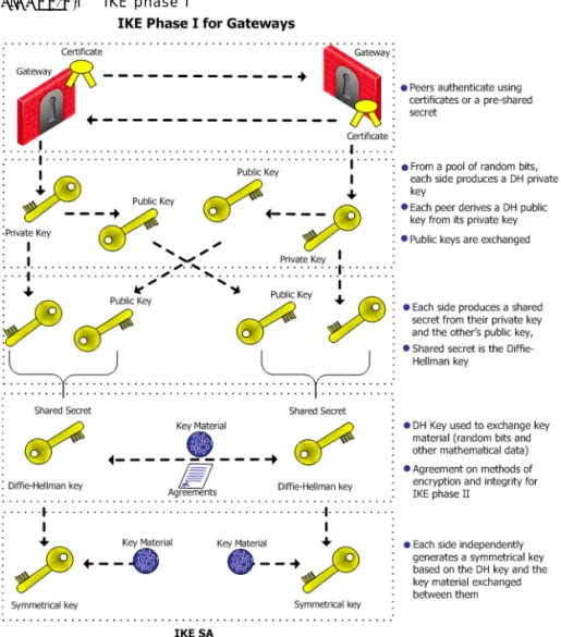
networks and protects the data passing between them. For example, an organization may have geographically spaced networks connected via the Internet; the company has connectivity but no privacy. VPN provides privacy by encrypting those connections that need to be secure. Another company may connect all parts of its geographically spaced network through the use of dedicated leased lines; this company has achieved connectivity and privacy but at great expense. VPN offers a cheaper connectivity solution by connecting the different parts of the network via the public Internet. A Virtual Private Network is a network that employs encrypted tunnels to exchange securely protected data. VPN-1 creates encrypted tunnels by using the Internet Key Exchange (IKE) and IP Security (IPSec) protocols. IKE creates the VPN tunnel, and this tunnel is used to transfer IPSec encoded data.
Think of IKE as the process that builds a tunnel, and IPSec packets as trucks that carry the encrypted data along the tunnel.
FIGURE 2-1 Simplified VPN tunnel
How it Works
In FIGURE 2-2, host 1 and host 6 need to communicate. The connection passes in the clear between host 1 and the local Gateway. From the source and destination addresses of the packet, the Gateway determines that this should be an encrypted connection. If this is the first time the connection is made, the local Gateway initiates an IKE negotiation with the peer Gateway in front of host 6. During the negotiation, both Gateways authenticate each other, and agree on encryption methods and keys. After a successful IKE negotiation, a VPN tunnel is created. From now on, every packet that passes between the Gateways is encrypted according to the IPSec protocol. IKE supplies
VPN Communities
authenticity (Gateways are sure they are communicating with each other) and creates the foundation for IPSec. Once the tunnel is created, IPSec provides privacy (through encryption) and integrity (via one-way hash functions).
FIGURE 2-2 Confidentiality, integrity, and authentication via IPSec.
After a VPN tunnel has been established (FIGURE 2-2), packets are dealt with in the following way:
• A packet leaves the source host and reaches the Gateway. • The Gateway encrypts the packet.
• The packet goes down the VPN tunnel to the second Gateway. In actual fact, the packets are standard IP packets passing through the Internet. However, because the packets are encrypted, they can be considered as passing through a private “virtual” tunnel.
• The second Gateway decrypts the packet.
• The packet is delivered in the clear to the destination host. From the hosts perspective, they are connecting directly.
For more information regarding the IKE negotiation, see: Understanding and Customizing IKE.
VPN Communities
Creating VPN tunnels between Gateways is made easier through the configuration of VPN communities. A VPN community is a collection of VPN enabled Gateways capable of communicating via VPN tunnels.
• VPN Community member. Refers to the Gateway that resides at one end of a VPN tunnel.
• VPN domain. Refers to the hosts behind the Gateway. The VPN domain can be the whole network that lies behind the gateway or just a section of that network. For example a Gateway might protect the corporate LAN and the DMZ. Only the corporate LAN needs to be defined as the VPN domain.
• VPN Site. Community member plus VPN domain. A typical VPN site would be the branch office of a bank.
• VPN Community. The collection of VPN tunnels/links and their attributes.
FIGURE 2-3 VPN Terminology
The methods used for encryption and ensuring data integrity determine the type of tunnel created between the Gateways, which in turn is considered a characteristic of that particular VPN community.
SmartCenter Server can manage multiple VPN communities, which means communities can be created and organized according to specific needs.
Remote Access Community
A Remote Access Community is a type of VPN community created specifically for users that usually work from remote locations, outside of the corporate LAN. This type of community ensures secure communication between users and the corporate LAN. For more information, see: “VPN for Remote Clients”.
VPN Topologies
VPN Topologies
The most basic topology consists of two Gateways capable of creating a VPN tunnel between them. SmartCenter Server’s support of more complex topologies enables VPN communities to be created according to the particular needs of an organization. SmartCenter Server supports two main VPN topologies:
• Mesh • Star
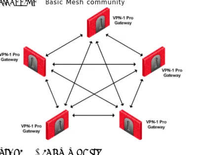
Mesh VPN Community
A Mesh is VPN community in which a VPN site can create a VPN tunnel with any other VPN site:
FIGURE 2-4 Basic Mesh community
Star VPN Community
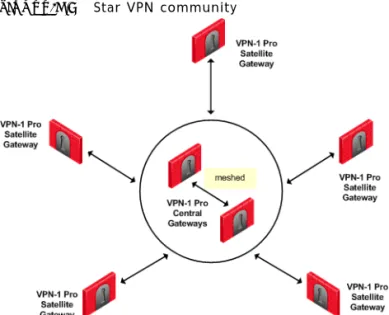
A star is a VPN community consisting of central Gateways (or “hubs”) and satellite Gateways (or “spokes”). In this type of community, a satellite can create a tunnel only with other sites whose Gateways are defined as central.
FIGURE 2-5 Star VPN community
A satellite Gateway cannot create a VPN tunnel with a Gateway that is also defined as a satellite Gateway.
Central Gateways can create VPN tunnels with other Central Gateways only if the
Mesh center gateways option has been selected on the Central Gateways page of the Star Community Properties window.
Choosing a topology
Which topology to choose for a VPN community depends on the overall policy of the the organization. For example, a mesh community is usually appropriate for an Intranet in which only Gateways which are part of the internally managed network are allowed to participate; Gateways belonging to company partners are not.
A Star VPN community is usually appropriate when an organization needs to exchange information with networks belonging to external partners. These partners need to communicate with the organization but not with each other. The organization’s Gateway is defined as a “central” Gateway; the partner Gateways are defined as “satellites”.
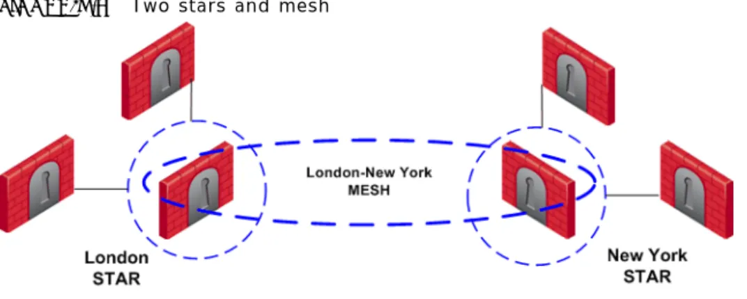
For more complex scenarios, consider a company with headquarters in two countries, London and New York. Each headquarters has a number of branch offices. The branch offices only need to communicate with the HQ in their country, not with each other; only the HQ’s in New York and London need to communicate directly. To comply with this policy, define two star communities, London and New York. Configure the London and New York Gateways as “central” Gateways. Configure the Gateways of
VPN Topologies
New York and London branch offices as “satellites”. This allows the branch offices to communicate with the HQ in their country. Now create a third VPN community, a VPN mesh consisting of the London and New York Gateways.
FIGURE 2-6 Two stars and mesh
Topology and Encryption Issues
Issues involving topology and encryption can arise as a result of an organization’s policy on security, for example the country in which a branch of the organization resides may have a national policy regarding encryption strength. For example, policy says the Washington Gateways should communicate using 3DES for encryption. Policy also states the London Gateways must communicate uses DES as the encryption algorithm. In addition, the Washington and London Gateways (as shown in FIGURE 2-7) need to communicate with each other using the weaker DES. Consider the solution in
FIGURE 2-7 Different means of encryption in separate Mesh communities
In this solution, Gateways in the Washington mesh are also defined as satellites in the London star. In the London star, the central Gateways are meshed. Gateways in Washington build VPN tunnels with the London Gateways using DES. Internally, the Washington Gateways build VPN tunnels using 3DES.
Special Condition for VPN Gateways
Individually, Gateways can appear in many VPN communities; however, two Gateways that can create a VPN link between them in one community cannot appear in another VPN community in which they can also create a link. For example:
VPN Topologies
FIGURE 2-8 Special condition
The London and New York Gateways belong to the London-NY Mesh VPN community. To create an additional VPN community which includes London, New York, and Paris is not allowed. The London and New York Gateways cannot appear “together” in more than one VPN community.
Two Gateways that can create a VPN link between them in one community can appear in another VPN community provided that they are incapable of creating a link between them in the second community. For example:
In FIGURE 2-9, The London and New York Gateways appear in the London-NY mesh. These two Gateways also appear as Satellite Gateways in the Paris Star VPN community. In the Paris Star, satellite Gateways (London and NY) can only
communicate with the central Paris Gateway. Since the London and New York satellite Gateways cannot open a VPN link between them, this is a valid configuration.
Authentication Between Community Members
Before Gateways can exchange encryption keys and build VPN tunnels, they first need to authenticate to each other. Gateways authenticate to each other by presenting one of two types of “credentials”:
• Certificates. Each Gateway presents a certificate which contains identifying information of the Gateway itself, and the Gateway’s public key, both of which are signed by the trusted CA. For convenience, VPN-1 has its own Internal CA that automatically issues certificates for all internally managed Gateways, requiring no configuration by the user. In addition, VPN-1 supports other PKI solutions. For more information, see: Using PKI Solutions.
• Pre-shared secret. A pre-shared is defined for a pair of Gateways. Each Gateway proves that it knows the agreed upon pre-shared secret. The pre-shared secret can be a mixture of letters and numbers, a password of some kind.
Considered more secure, certificates are the preferred means. In addition, since the Internal CA on the SmartCenter Server automatically provides a certificate to each VPN-1 Gateway it manages, it is more convenient to use this type of authentication. However, if a VPN tunnel needs to be created with an externally managed Gateway (a Gateway managed by a different SmartCenter Server) the externally managed Gateway: • Might support certificates, but certificates issued by an external CA, in which case
both Gateways need to trust the other’s CA. (See: “Using PKI Solutions”.”For more information, see: “Configuring a VPN with External Gateways Using PKI” on page 69.)
• May not support certificates; in which case, VPN-1 supports the use of a
“pre-shared secret”. For more information, see: “Configuring a VPN with External Gateways Using a Pre-Shared Secret” on page 72.
A “secret” is defined per external Gateway. If there are five internal Gateways and two externally managed Gateways, then there are two pre-shared secrets. The two pre-shared secrets are used by the five internally managed Gateways. In other words, all the internally managed Gateways use the same pre-shared secret when
Access Control and VPN Communities
Access Control and VPN Communities
Configuring Gateways into a VPN community does not create a de facto access control policy between the Gateways. The fact that two Gateways belong to the same VPN community does not mean the Gateways have access to each other.
The configuration of the Gateways into a VPN community means that if these Gateways are allowed to communicate via an access control policy, then that
communication is encrypted. Access control is configured in the Security Policy Rule Base.
Using the VPN column of the Security Policy Rule Base, it is possible to create access control rules that apply only to members of a VPN community, for example:
The connection is matched only if all the conditions of the rule are true, that is - it must be an HTTP connection between a source and destination IP address within VPN Community A. If any one of these conditions is not true, the rule is not matched. If all conditions of the rule are met, the rule is matched and the connection allowed. It is also possible for a rule in the Security Policy Rule Base to be relevant for both VPN communities and host machines not in the community. For example:
FIGURE 2-10 Access control in VPN communities TABLE 2-1
Source Destination VPN Service Action
The rule in the Security Policy Rule base allows an HTTP connection between any internal IP with any IP:
In FIGURE 2-10, an HTTP connection between host 1 and the Internal web server behind Gateway 2 matches this rule. A connection between the host 1 and the web server on the Internet also matches this rule; however, the connection between host 1 and the internal web server is a connection between members of a VPN community and passes encrypted; the connection between host 1 and the Internet web server passes in the clear.
In both cases, the connection is simply matched to the Security Policy Rule; whether or not the connection is encrypted is dealt with on the VPN level. VPN is another level of security separate from the access control level.
Accepting all Encrypted Traffic
If you select Accept all encrypted traffic on the General page of the VPN community
Properties window, a new rule is added to the Security Policy Rule Base. This rule is neither a regular rule or an implied rule, but an automatic community rule, and can be distinguished by its “beige” colored background.
Excluded Services
In the VPN Communities Properties window Excluded Services page, you can select services that are not be encrypted, for example FireWall-1control connections. Services in the clear means “do not make a VPN tunnel for this connection”. For further information regarding control connections, see: “How to Authorize FireWall-1 Control Connections in VPN Communities” on page 75”.
Special Considerations for Planning a VPN Topology
When planning a VPN topology it is important to ask a number of questions: 1 Who needs secure/private access?
2 From a VPN point of view, what will be the structure of the organization? 3 Internally managed Gateways authenticate each other using certificates, but how
will externally managed Gateways authenticate?
• Do these externally managed Gateways support PKI?
Source Destination VPN Service Action
Enabling Simplified Mode
Configuring a VPN Between Gateways
VPN communities can be configured in either traditional or simplified mode. In
Traditional mode, one of actions available in the Security Policy Rule Base is Encrypt. When encrypt is selected, all traffic between the Gateways is encrypted. VPN is more easily configured through the use of VPN communities, otherwise known as working in Simplified Mode. For more information regarding traditional mode, see: “Traditional Mode VPNs”.
Enabling Simplified Mode
To switch from Traditional mode to Simplified:
1 In Global Properties >VPN-1 Pro page, select either Simplified mode to all new Security Policies, or Traditional or Simplified per new Security Policy.
2 File > Save. (If you do not save, you are prompted to do so). 3 File > New... The New Policy Package window opens.
4 Create a name for the new security policy package and select Security and Address Translation.
5 For the VPN configuration method, select Simplified mode (if you selected
Traditional or Simplified per new Security policy in Global Properties). Click OK. In the Security Policy Rule base, a new column marked VPN appears and the Encrypt
option is no longer available in the Action column. You are now working in Simplified Mode.
Configuring a Mesh Community Between Internally Managed
Gateways
Internally managed VPN communities have one of two possible topologies; mesh or star. (For externally managed Gateways, see: VPN-1 Advanced Configuration.) To configure an internally managed VPN mesh community, create the network objects (Gateways) first and then add them to the community:
1 In the Network Objects tree, right click Network Objects > New > Check Point >
Gateway...Select Simple mode (wizard) or Classic mode. The Check Point Gateway properties window opens.
Note - If you upgrade VPN-1 from 4.1 to NG, select in the Global Properties window: Simplified mode to all new security policies. This means new policies are created using Simplified mode.
a On the General Properties page, after naming the object and supplying an IP address, select VPN-1 Pro or VPN-1 Net and establish SIC communication. b On the Topology page, click Add to add interfaces. Once an interface
appears in the table, clicking Edit... opens the Interface Properties window. c In the Interface Properties window, define the general properties of the
interface and the topology of the network behind it.
d Still on the Topology page, VPN Domain section, define the VPN domain as either all the machines behind the Gateway based on the topology information or manually defined:
i As an address range. ii As a network.
iii As a group, which can be a combination of address ranges, networks, and even other groups.
(There are instances where the VPN domain is a group which contains only the Gateway itself, for example where the Gateway is acting as a backup to a primary Gateway in a MEPed environment.)
The network Gateway objects are now configured, and need to be added to a VPN community.
2 On the Network objects tree, select the VPN Communities tab.
ARight-click Site to Site.
BFrom the short-cut menu, select New Site To Site... > Meshed. The Meshed Communities Properties window opens.
COn the General page, select Accept all encrypted traffic if you need all traffic between the Gateways to be encrypted. If not, then create appropriate rules in the Security Policy Rule Base that allows encrypted traffic between
community members.
DOn the Participating Gateways page, add the Gateways created in step 1. A VPN tunnel is now configured. For more information on other options, such as VPN Properties, Advanced Properties, and Shared Secret, see: “Understanding and
Note - There is nothing to configure on the VPN page, regarding certificates, since internally managed Gateways automatically receive a certificate from the internal CA.
Configuring a Star VPN Community
3 If you did not select Accept all encrypted traffic in the community, build an access control policy, for example:
Where “Meshed community” is the VPN community you have just defined.
Configuring a Star VPN Community
A star VPN community is configured in much the same way as a mesh community, the difference being the options presented on the Star Community Properties window: • On the General page, Enable VPN routing for satellites section, select a To center
only. For more information on VPN routing, see the “VPN Routing”. • On the Central Gateways page, Add... the central Gateways.
• On the Central Gateways page, select Mesh central gateways if you want the central gateways to communicate.
• On the Satellite Gateways page, Add... the satellite Gateways.
Confirming a VPN Tunnel Successfully Opens
To confirm a VPN tunnel has successfully opened:
1 Edit a rule in the Security Policy Rule base that encrypts a specific service between Member Gateways of a VPN community, for example FTP.
2 Select log as the tracking option.
3 Open an appropriate connection, in this example FTP session from a host behind the first Gateway to an FTP server behind the second.
4 Open SmartView Tracker and examine the logs. The connection appears as encrypted, as in FIGURE 2-11.
FIGURE 2-11 Sample log TABLE 2-2
Source Destination VPN Service Action
C H A P T E R
3
Using PKI Solutions
In This Chapter
Need for Integration with Different PKI solutions
X.509-based PKI solutions provide the infrastructure that enables entities to establish trust relationships between each other based on their mutual trust of the Certificate Authority (CA). The trusted CA issues a certificate for an entity, which includes the entity’s public key. Peer entities that trust the CA can trust the certificate — because they can verify the CA’s signature — and rely on the information in the certificate, the most important of which is the association of the entity with the public key.
IKE standards recommend the use of PKI in VPN environments, where strong authentication is required.
A VPN-1 module taking part in a VPN tunnel establishment must have an RSA key pair and a certificate issued by a trusted CA. The certificate contains details about the module’s identity, its public key, CRL retrieval details, and is signed by the CA. When two entities try to establish a VPN tunnel, each side supplies its peer with some information signed by its private key and with the certificate that contains the public key. The certificate enables the establishment of a trust relationship between the gateways; each gateway uses the peer gateway’s public key to verify the source of the signed information and the CA’s public key to validate the certificate’s authenticity. In other words, the validated certificate is used to authenticate the peer.
Need for Integration with Different PKI solutions page 39
Solution - Supporting a Wide Variety of PKI Solutions page 40
PKI Considerations page 46
Every deployment of Check Point SmartCenter server includes an Internal Certificate Authority (ICA) that issues VPN certificates for the VPN-1 modules it manages. These VPN certificates simplify the definition of VPNs between these modules. For more information about the ICA, see Chapter 3, “The Internal Certificate Authority (ICA) and the ICA Management Tool” in the SmartCenter Guide.
In some situations, integration with other PKI solutions is required, for example: • A VPN must be established with a VPN-1 module managed by an external
SmartCenter server. For example, the peer gateway belongs to another organization which utilizes Check Point products, and its certificate is signed by its own SmartCenter server’s ICA.
• A VPN must be established with a non-Check Point VPN entity. In this case, the peer’s certificate is signed by a third-party CA.
• An organization may decide, for whatever reason, to use a third party CA to generate certificates for its VPN-1 modules.
Solution - Supporting a Wide Variety of PKI Solutions
VPN-1 supports many different scenarios for integrating PKI in VPN environments. • Multiple CA Support for Single VPN Tunnel – Two Check Point VPN-1 modules
present a certificate signed by different ICAs.
• Support for non-ICA CAs – In addition to ICA, VPN-1 supports the following CAs: • External ICA - The ICA of another SmartCenter
• Other OPSEC certified PKI solutions • Entrust CA
• CA Hierarchy – CAs are often arranged in an hierarchical structure where multiple CAs are subsidiary to the root CA. VPN-1 supports a CA hierarchy of as many as 32 levels.
PKI and Remote Access Users
VPN-1 supports certificates not only for gateways but for users as well. See “VPN for Remote Clients”” for information about user certificates.
PKI Deployments and VPN
Following are some examples of CA deployments and the respective typical VPN scenarios. Since VPN-1 can establish VPN tunnels with various other VPN solutions (internally managed, externally managed and non-Check Point VPN solutions) and with different CA types, a wide variety of VPN scenarios is possible.
PKI Deployments and VPN
Simplest Deployment – Internal CA
When the VPN tunnel is established between gateways managed by the same
SmartCenter server, each peer has a certificate issued by the SmartCenter server’s ICA.
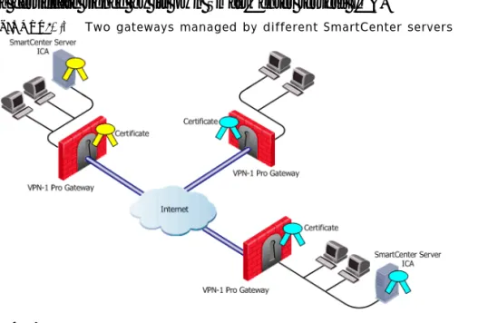
CA of An External SmartCenter Server
If a VPN gateway is managed by an external SmartCenter server (for example, when establishing a VPN tunnel with another organization’s VPN-1 modules), each peer has a certificate signed by its own SmartCenter server’s ICA.
FIGURE 3-1 Two gateways managed by different SmartCenter servers
CA Services Over the Internet
If a VPN gateway’s certificate is issued by a third party CA accessible over the Internet, CA operations such as registration or revocation are usually performed through HTTP forms. CRLs are retrieved from an HTTP server functioning as a CRL repository. FIGURE 3-2 depicts a CA and CRL repository accessible over the Internet.
FIGURE 3-2 CA services are on the Internet
CA is located on the LAN
If the peer VPN gateway’s certificate is issued by a third party CA on the LAN, the CRL is usually be retrieved from an internal LDAP server. FIGURE 3-3 depicts such a situation.
FIGURE 3-3 Third Party CA deployed locally
Trusting a CA – Overview
A trust relationship is a crucial prerequisite for establishing a VPN tunnel. However, it is possible only if the CA that signs the peer’s certificate is trusted. The following sections describe how to configure support for PKI operations and X.509 certificates in
Enrolling a Managed Entity
Trusting a CA means obtaining and validating the CA’s own certificate. Once this is done, the details on the CA certificate and its public key can be used both to obtain and validate certificates issued by the CA.
The Check Point Internal CA (ICA) is automatically trusted by all modules managed by the SmartCenter server that deploys the ICA. Other CAs are not automatically trusted, so a module must first obtain the CA’s certificate and validate it.
To obtain a CA’s certificate, proceed as follows:
• ICA of an external SmartCenter server — See Chapter 3, “The Internal Certificate Authority (ICA) and the ICA Management Tool in the SmartCenter Guide for information on how to do this.
• OPSEC Certified CA — Use the CA tools.
• Entrust CA — Because the Entrust CA certificate is delivered during the enrollment process, there are two possibilities:
• If the Entrust CA issues certificates for modules managed by the SmartCenter server, then the SmartCenter server already has the Entrust CA’s certificate. • If the Entrust CA issues certificates only for other VPN entities, then the CA
certificate must be obtained from those entities.
Enrolling a Managed Entity
Enrollment means obtaining a certificate from a CA, that is, requesting that the CA issue a certificate for an entity.
The process of enrollment begins with generation of key pair. A certificate request is then created out of the public key and additional information about the module. The type of the certificate request and the rest of the enrollment process depends on the CA type.
The case of an internally managed gateway is the simplest, because the ICA is located on the SmartCenter server machine. The enrollment process is completed with no administrator intervention.
To obtain a certificate from an OPSEC Certified CA, SmartCenter server takes the module details and the public key and encodes a PKCS#10 request. The request (which can include SubjectAltName for OPSEC certificates and Extended Key Usage extensions) is delivered to the CA manually by the administrator. Once the CA issues the certificate the administrator can complete the process by importing the certificate to the
In the case of an Entrust CA, the CA administrator supplies the SmartCenter server administrator with a Reference Number and Authorization code. The SmartCenter server communicates with the Entrust CA directly, authenticates with this information and completes the enrollment.
An Entrust CA is supported for versions 3.0. 4.0, 5.0, and 6.0. By default, a certificate is enrolled using the Entrust CMS library. For Entrust 5.0 and 6.0, certificates are enrolled using the standard CMP protocol.
Validation of Certificate
When an entity receives a certificate from another entity, it must validate it as follows: • Verify the certificate signature, i.e. verify that the certificate was signed by a trusted
CA
If the certificate is not signed directly by a trusted CA, but rather by a subsidiary of a trusted CA, the path of CA certificates is verified up to the trusted CA.
• Verify that the certificate chain is not expired.
• Verify that the certificate chain is not revoked. A CRL is retrieved to confirm that the serial number of the validated certificate is not included among the revoked certificates.
In addition, VPN-1 verifies the validity the certificate’s use in the given situation, confirming that:
• The certificate is authorized to perform the action done. If, for example, the private key was used to sign some data (e.g., for authentication) the KeyUsage extension on the certificate – if it is present – is checked to see if this is permitted. • The peer used the correct certificate in the negotiation. When creating a VPN
tunnel with externally managed module, the administrator may decide that only a certificate signed by a specific CA from among the trusted CAs is accepted. Acceptance of certificates with specific details such as Distinguished Name (DN) is possible as well.
Revocation Checking
VPN-1 can retrieve the CRL from either an HTTP server or an LDAP server. If the CRL repository is an HTTP server, the module uses the URL published in the CRL Distribution Point extension in the certificate and opens an HTTP connection to the CRL repository to retrieve the CRL.
If the CRL repository is an LDAP server, VPN-1 attempts to locate the CRL in one of the LDAP account units defined. In this case, definition of LDAP account unit is required. If the CRL Distribution Point extension exists, it publishes the DN of the
Validation of Certificate
CRL, namely, the entry in the Directory under which the CRL is published or the LDAP URI. If the extension does not exist, VPN-1 tries to locate the CRL in the entry of the CA itself in the LDAP server.
CRL Prefetch-Cache
Since the retrieval of CRL takes a long time in comparison to the entire IKE negotiation process, VPN-1 stores the CRLs in a CRL cache so that later IKE negotiations do not require repeated CRL retrievals.
The cache is pre-fetched: • every two hours • on policy installation • when the cache expires
If the pre-fetch fails, the previous cache is not erased.
An administrator can shorten the lifetime of a CRL in the cache or even to cancel the use of the cache. If the CRL Cache operation is cancelled, the CRL must be retrieved for each subsequent IKE negotiation, thus considerably slowing the establishment of the VPN tunnel. Because of these performance implications, it is recommend that CRL caching be disabled only when the level of security demands continuous CRL retrieval. See also: “Modifying the CRL Pre-Fetch Cache” on page 55.
Special Considerations for the CRL Pre-fetch Mechanism
The CRL pre-fetch mechanism makes a “best effort” to obtain the most up to date list of revoked certificates. However, after the cprestart command has been executed, the cache is no longer updated. The Gateway continues to use the old CRL for as long as the old CRL remains valid (even if there is an updated CRL available on the internal CA). The pre-fetch cache mechanism returns to normal functioning only after the old CRL expires and a new CRL is retrieved from the internal CA.
To manually update the CRL:
• After exececuting cprestart, run crl_zap to empty the cache, or:
• In Global properties > SmartDashboard Customization > Configure > Check Point CA properties > select: flush_crl_cache_file_on_install.
When a new policy is installed, the cache is flushed and a new CRL is retrieved from the internal CA.
CRL Grace Period
Temporary loss of connection with the CRL repository or slight differences between clocks may cause valid of CRLs to be considered invalid—and thus the certificates to be invalid as well—although the problem is momentary. VPN-1 offers a way to overcome this problem by supplying a CRL Grace Period. During this period, a CRL is
considered as valid although if strictly adhering to the CRL validity time it not.
PKI Considerations
In This Section
Using the Internal CA vs. Deploying a Third Party CA
The Internal CA makes it very easy to use PKI for Check Point applications such as site-to-site and remote access VPNs. However, an administrator may prefer to continue using a CA that is already used within the organization, for generalized applications such as secure email, and disk encryption.
Using the Internal CA vs. Deploying a Third Party CA page 46