> BCM Handbook
This is the Way. This is Nortel, Nortel, the Nortel logo, the Globemark, Norstar, Call Pilot and Meridian 1 are
trademarks of Nortel Networks. All other trademarks are the property of their owners.
Copyright © 2005 Nortel Networks. All rights reserved. Information in this document is subject to change without
notice. Nortel assumes no responsibility for any errors that may appear in this document.
Table of Contents
Introduction ...16
The Business Communications Manager 16 The BCM Portfolio 17 Introduction to Digital Mobility 19 Introduction to BCM50 19 About This Handbook 20 Hardware ...22
BCM200/400 Hardware 23 BCM50 Hardware 25 Physical Interfaces ...26
BCM50 Expansion Unit...26
BCM50a/e Integrated Routers ...27
BCM50 Data Networking Hardware Components ...31
BCM50 Modem ...31
BCM50 LAN Interface ...31
BCM200/400 Components 32 Connection Ports...32
Business Communications Manager LEDs ...32
Telephony Hardware Components 33 Media Services Card...33
Station Media Bay Modules ...37
Business Communications Manager Expansion Cabinet 48
Data Networking Hardware Components 49
Modem...49 LAN Interface...50 WAN Interface Card...50
Serviceability Improvements 51
Upgrade Support for Installed Base...51
Business Series Terminals 52
Overview of Portfolio ...53
Advanced Features 58
Audio Control Center...58 Business Series Terminals Feature Comparison...59 Desktop Assistant Button Labeling Application...60
Business Communications Manager Accessories 61
Analog Terminal Adapters...61 NACU ...63 Station Auxiliary Power Supply (SAPS) ...63
IP Telephones 64
Desktop Solutions 65
Nortel IP Phone 2001...65 Nortel IP Phones 2002, 2004, & 2007 ...66
Software Solutions 68
Multiple Platform Support ...69
Integrated Switched Ethernet Connection ...69
Reliable LAN Power Options ...70
Future-Proof...71
IP Set Features and Programming ...72
Telephony ...74
CLASS/CMS Features 74 Call Detail Recording (CDR) 75 CDR Enhancements...76
Report Information ...77
Call Detail Recording Display...78
Call Detail Recording Record Security...79
Telephony Features 79 Data Capabilities ...94 Routing Services 94 IP...94 Static Routing ...95 RIP ...96 RIP v2 ...96 OSPF...97 Packet Filtering...99 IP Services 100 Network Address Translation (NAT) ...100
Port Address Translation (PAT) ...101 DHCP...101 DNS ...102 IPSec ...103 PPTP ...103 Web Caching ...104 T.38 Fax over IP ...105
Communication Server interoperability via H.323...105
SIP Trunk & Data Services Support ...105
LAN Connections 106 LAN-to-LAN Fast Path Routing...106
WAN Connections 106 Frame Relay...107
Point-to-Point Protocol ...108
Point-to-Point Protocol over Ethernet (PPPoE)...109
Quality of Service (QoS) 109 QoS Module and VoIP QoS Monitor ...109
Common Open Policy Service (COPS) ...110
Data Capabilites of the BCM50 111 VPN ...112
Security Services ...112
IP Services ...112
Messaging ...114
Messaging Overview 116 Messaging Components...116
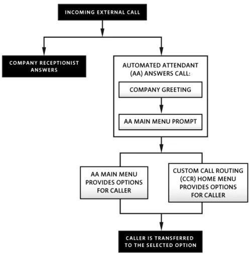
Automated Attendant...116
Mailboxes (Voice Messaging) ...116
Custom Call Routing (CCR)...116
Networking ...117
Unified Messaging...117
Fax Messaging ...117
DTMF User Choice ...117
Automated Attendant...119
Voice Messaging Call Answering Overview...120
Custom Call Routing (CCR)...121
Mailboxes ...122
Unified Messaging 126 Unified Messaging User Interface ...128
Messaging Feature Codes 129 Feature Descriptions 130 Administration ...130
AMIS Networking ...131
Digital Networking ...131
Fax Messaging Features...135 Group Lists ...135 Mailbox Features ...136 Miscellaneous Features...139 Reports...141 Security Features ...142
Voice Over IP (VoIP) ...144
VoIP for BCM50 144 Voice over IP Trunk Capability 145 VoIP Features ...145
VoIP Gateway...146
Network Quality of Service ...147
Network Performance Utilities ...148
Codecs...148
Silence Compression ...149
Echo Cancellation...151
Jitter Buffer...151
Voice over IP Stations ...152
Media Path Management on LAN ...153
Media Path Management/WAN...155
Media Path Remote Site ...156
Voice Networking ...160
Meridian Customer Defined Networking (MCDN) or IP Trunks 160 Lines/Trunks Used for Networking 160 Analog Lines...160
T-1 Trunks (Loop Start, E&M, DID, Ground Start)...161
Digital Drop and Insert MUX (DDIM)...161
PRI Trunks...161 BRI Lines...161 IP Trunks ...162 DPNSS...162 Networking Applications 162 Dialing Plans...162 Access Using BCM 163 Public Network ...163 Private Network ...163
Remote System Access to BCM...164
PRI Networking Using Call-by-Call Services ...164
IP Telephony and Communication Server 1000 Networking...166
Public Versus Private Received Digits ...167
BCM and a Gatekeeper 167 Toll Bypass with VoIP Gateway ...168
Call Center ...180
Call Center for BCM50 180 Call Center on BCM200/400 181 Intelligent Integration of Call Center 182 Professional Call Center and Basic Call Center 183 Call Center Features ...185
Hardware Requirements ...194
Multimedia Call Center 194 Multimedia Call Center Features...195
Call Center Reporting 196 Real-Time Status Display ...197
Hardware Requirements of Reporting for Call Center ...200
Wallboards and Softboards...201
ipView Softboard...203
PC Requirements ...206
Call Center Keycodes 206 Basic Call Center Keycode ...206
Reporting for Call Center Keycode ...206
Basic Call Center to Professional Call Center Upgrade Keycode ...207
Basic Call Center to Professional with Reporting Upgrade Keycode ...207
Professional Call Center Keycode ...207
Multimedia Call Center Keycode ...207
Interactive Voice Response (IVR) ...210
IVR Features 210 Flexibility Built in for Multiapplication Environments ...210
Designed for Smooth Migration and Growth ...210
Professional Services 211 Nortel Customer Contact and Voice Portal Solutions ...211
Standard Features 212 Run Time Engine...212
The Application ...212
System Development Tools ...213
System Management Tools...213
IVR and BCM: Other Applications 214 Media Processing Features ...214
Database Support ...214
IVR Park & Page ...215
IVR Messaging Integration...215
Mobility Solutions...218
Digital Mobility Solution 218 Digital Mobility Controllers ...219
Digital Mobility Base Stations...221
Digital Mobility Repeaters...222
Digital Mobility Handsets...222
Digital Mobility Software...224
Wireless LAN 2200 226 Wireless Handsets...226
Business Series Terminal T7406 Cordless ...228
Computer Telephony Integration (CTI)...232
TAPI 232 BCM LAN CTE...232
Personal Call Manager...233
System Requirements ...236
Virtual Private Networks (VPN) ...240
Virtual Private Networking on BCM50 240 Virtual Private Networking on BCM200/400 241 VPN Infrastructure 242 VPN Service Models 242 Service Provider to Service Provider Model ...243
Service Provider to Enterprise Service Provider Model ...244
Enterprise to Enterprise Service Model ...244
VPN Security 245 Privacy ...245
Authenticity and Integrity...246
VPN Enabling Technologies 246 Encryption...246
Authorization ...247
VPN Typical Applications 248 Medium/Large Business ...248
Small- to Medium-Sized Business...249
Extranets ...249
Nortel Complete VPN Solution 250 BCM Virtual Private Networking (VPN) Support 251 IPSec ...251
IPSec Client Support...253
PPTP ...253
Secure Sockets Layer (SSL) ...254
Secure Shell (SSH) ...254
Access Control...254
Denial of Service (DoS) prevention...255
Limiting BCM information revealed publicly ...255
System Management and Software Options ...258
BCM200/400: Unified Manager 260 Unified Manager Capabilities...260
BCM Management Access Options for BCM200/400 262 BCM Unified Manager Interface for the BCM200/400 ...263
Resources Menu...267
Services Menu ...269
BCM200/400 Backup and Restore ...270
BCM200/400 Fault Management ...271
BCM50 Management Environment...272
BCM Management Access Options for BCM50 ...272
BCM50 Element Manager ...273
The Element Manager Administration interface...274
CallPilot Manager OA&M Interface 275 System Monitoring with BCM Monitor ...276
Network Configuration Manager (NCM) 277 NCM Architecture ...278
NCM Tasks...279
BCM User Managed Functions 281 Software Keycodes 282 BCM200/400 Keycodes...283 BCM50 Keycodes 285 Server/Client Software 289 Glossary...292 Index ...334
> Introduction
Hardware
Telephony
Data Capabilities
Messaging
Voice Over IP (VoIP)
Voice Networking
Call Center
Interactive Voice Response (IVR)
Mobility Solutions
Computer Telephony Integration (CTI)
Virtual Private Networks (VPN)
System Management and Software Options
Glossary
Introduction
The Business Communications Manager (BCM) Handbook is a reference tool designed for representatives who sell the Nortel Enterprise product portfolio in North America. The Business Communications Manager product is referred to as BCM throughout this handbook.
This handbook is intended for reference purposes only. Please consult Configuration and Pricing Support,
specifically the Global Product Price Catalogue (GPPC) or the Nortel Networks Enterprise Configurator (NNEC). The configurations and applications mentioned in this handbook may not be standard offerings with your
company.
The Business Communications Manager
Nortel delivers global, industry-leading enterprise solutions for businesses of all types and sizes. These solutions include communications systems, call center and multimedia messaging applications, in addition to data access products. Our customer-driven solutions increasingly take advantage of Internet and computer integration, helping drive business performance and creating a greater competitive advantage for our customers. One of the Nortel enterprise communications solutions is the BCM.
Originally introduced to the market in early 2000, Nortel BCM solution is one of the most sophisticated and reliable converged voice and data solutions available for branch offices and small- to medium-sized businesses. The BCM is a converged communications system that delivers Nortel reliable and proven voice processing, feature-rich business telephony applications and data networking services over a single platform that is managed via a browser-based tool. As a highly reliable, scalable and integrated voice and data solution, BCM is designed to align with the universal core objectives of the single-site, medium-sized and multisite enterprise to increase revenues, improve customer service, streamline costs and expand market reach.
BCM has been designed to allow customers to build on the platform by adding applications as needed. Risk-averse customers can start with PSTN and migrate to IP when the time is right. With BCM, disparate systems, equipment, and applications such as voice messaging, auto attendant and call center functionality can be consolidated in one box in order to reduce costs and to create a consistent customer and employee experience across the organization.
The BCM Portfolio
BCM comes in a portfolio of three models, each of which has been designed for maximum flexibility and scalability. All of them support pluggable and interchangeable Media Bay Modules that provide the basis for delivering BCM’s many applications. Here are the three models:
• BCM50 supports up to 20 users, and comes in a streamlined combination of a main module plus optional expansion modules.
• BCM200 provides two bays for Media Bay Modules, and has a lower removable tray, similar to that in the BCM400, for improved serviceability of the platform in a lower-cost version. It’s designed to support 32 users or fewer per system.
• BCM400 is available in a standard model or a redundant feature option model, which includes four Media Bay Modules, which simplifies configurations that require four modules and eliminates the need for an Expansion Cabinet. When coupled with an Expansion Cabinet, the BCM 400 can grow to support a maximum of 192 digital stations or up to 90 IP telephones, depending on the configuration.
Figure 1.
For multi-site organizations, BCM offers advanced voice and data networking capabilities that allow employees to effectively collaborate, independent of their office location. And, with Unified Manager, or Element Manager on BCM50, SMBs can maximize cost effectiveness and simplify management by using a single point to control and program individual BCM systems. These single-point management tools minimize onsite visits and can reduce or even eliminate the need for dedicated IT staff at each office location.
BCM is a voice and data communications system that delivers Nortel’s reliable and proven voice processing, feature-rich business telephony applications and data networking services over a single platform. BCM’s
approach to IP telephony literally transforms multiple networks into a single multi-service network while driving simplicity to the desktop. BCM offers increased application performance and enhancements in the areas of core telephony, data, mobility, management and serviceability. And, it provides unparalleled ROI for vertical markets spanning manufacturing to retail to healthcare.
Introduction to Digital Mobility
The Digital Mobility Solution is a high quality, integrated in-building cellular solution that is ideal for office, industrial, and campus environments. Using a series of base stations and repeaters to extend mobility across a workplace, the Digital Mobility Solution enables handoffs between access points, allowing people to stay connected on a call while moving across the office or campus. The Digital Mobility Solution is based on the Digitally Enhanced Cordless Telephony (DECT) technology. It is supported on the BCM200/400 and scales from 1 to 64 users and covers an area up to 1.5 million square feet for true campus-wide mobility.
For more information, see the chapter entitled “Mobility Solutions”.
Introduction to BCM50
BCM50 is a smaller but robust member of the BCM family aimed at businesses with fewer than 20 employees. While the BCM50 can not offer some advanced capabilities in Call Center and IVR as both the 200/400 do,. Because of the price-sensitivity of typical BCM50 target customers, some applications, like Professional Call Center, Multimedia Call Center, IVR, Digital and WLAN mobility, are not currently enabled on BCM50. Despite this, it fulfills most business needs for small enterprises without incurring excessive costs or equipment. BCM50 is the solution for customers with smaller sites because it delivers on price, while still enabling them to adopt key advanced services when they need them, offering increased platform scalability up to 44 Digital users and/or 32 IP users and core high value applications including Messaging, Unified Messaging and Call Center.
BCM50 has all applications loaded, so that businesses can activate applications as needed using Keycodes, reducing the front-end cost of implementation. BCM50 extends the classic BCM capabilities, previously available only to larger-sized organizations, into a converged, small-site solution that can serve as few as three desktops. BCM50 can be deployed as a pure IP solution, a converged solution, or as a traditional digital solution. The BCM50 Main Unit is available in three versions:
• A BCM50 with no router
• A BCM50 with Ethernet Router (BCM50e), and
• A BCM50 with ADSL Router (BCM50a).
Customers can choose Ethernet or ADSL, depending on what type of data service they use now. If they want to adopt more advanced data options, they can select a BCM50 without an integrated router and combine that with a more advanced Nortel routing solution, such as Contivity Secure Routing.
Customers can install up to two expansion units, which support optional Media Bay Modules. BCM50 is desk-, wall-, and rack-mountable, so it can fit easily into any workspace.
About This Handbook
This Handbook is organized into short and concise sections that are intended for reference use. This format allows you to easily locate and use the most relevant sections for a current project or request for information. The
information you find here will help make your sales easier, quicker and more professional. This Handbook contains the following chapters:
• Introduction
• Hardware
• Telephony
• Data Capabilities
• Messaging
• Voice Over IP (VoIP)
• Voice Networking
• Call Center
• Interactive Voice Response (IVR)
• Mobility Solutions
• Computer Telephony Integration (CTI)
• Virtual Private Networks (VPN)
• System Management and Software Options
Introduction
> Hardware
Telephony
Data Capabilities
Messaging
Voice Over IP (VoIP)
Voice Networking
Call Center
Interactive Voice Response (IVR)
Mobility Solutions
Computer Telephony Integration (CTI)
Virtual Private Networks (VPN)
System Management and Software Options
Glossary
Hardware
BCM takes advantage of today’s technology and has the following components:
• Base units
• Media Bay Modules (MBM)
• Media Services Card (MSC)
• Business Series Terminals (BST)
• Legacy Terminals
• IP Terminals Figure 2.
BCM400 BCM200
BCM200/400 Hardware
The BCM200 and BCM400 chassis comes fully equipped with a 1.2 GHz Intel Celeron processor, 256Mb of RAM, a 20-GB hard drive and a 350-watt power supply, all housed in a 19-inch, rack-mountable chassis. The chassis also comes equipped with integrated features like voice, data and management applications working in concert with Microsoft Windows NT 4.0 Embedded operating system, fully supported into 2006.
The main component of the BCM is the base unit. The base unit contains the following powerful parts:
• 2 10/100 BaseT Ethernet ports (on-board)
• 1 V.90 embedded modem (North America units only)
• 2 PCI slots (one used by the Media Services Card and one for adding a WAN interface card)
• 4 media bays in BCM400, 2 media bays in BCM200
• 350-watt power supply (PS)
• Windows NTE 4.0 (BCM400/BCM200), Linux OS (BCM50)
The BCM base unit controls all tasks, including call processing, voice messaging and data routing. The base unit also contains telephony hardware and data networking hardware components.
Making and receiving calls is crucial to any business. The call processing capability of BCM has been designed to process calls even when the Windows NT 4.0 Embedded operating system is out of service.
The BCM has been designed for flexibility and scalability, with support for pluggable and interchangeable Media Bay Modules. The BCM400 platform has availability for four Media Bay Modules, which simplifies
configurations and eliminates the need for the Expansion Cabinet. It also reduces the total cost of ownership for this configuration. When coupled with an Expansion Cabinet, the system can grow to support a maximum of 192 digital stations or up to 90 IP telephones. This is configuration dependent. 240 stations is the maximum capacity, with a mix of IP and digital stations, when 100% IP trunking is used. The BCM400 is available in a standard model or a redundant feature option model, which includes dual, hot-swappable power supply, dual chassis cooling fan and RAID mirrored hard disk drive redundancy.
Figure 3.
BCM is also available on the BCM200 platform, which provides two bays for Media Bay Modules. The BCM200 has a lower removable tray, similar to that in the BCM400, for improved serviceability of the platform in a lower-cost version. The BCM200 cannot be expanded using an Expansion Cabinet and is designed to meet the needs of customers with 32 or fewer users per system. The BCM200 comes in the standard version and may be upgraded in the field with an RAID upgrade kit with dual mirrored hard drive.
BCM50 Hardware
For customers with need for a small-site converged solution for 20 or fewer desktops, the BCM is also available on the BCM50 platform.
Figure 5.
BCM50 is delivered in a compact, plastic enclosure designed to ensure that there is no need to add additional hardware to enable all features and applications. The compact size and flexible installation options support fast installs and recognize the diverse environmental / physical conditions that can be found in small businesses. BCM50 main module and BCM50 expansion module share the following packaging attributes:
• Approximate dimensions 12” x 8.5” x 2.5”
• External power supply
• Units may be stacked and include design details to “lock” the units together in the stack
• Can be installed on desktop or shelf. Includes rubber feet.
• Optional Wall Mount bracket.
Physical Interfaces
BCM50 is tailored to meet the capacity requirements of many small businesses using the interfaces on the main unit without having to add any further hardware. This optimizes cost effectiveness of the system into locations with less than 10 stations which are often the businesses with the highest price sensitivity. Each system ships with no paths open. You activate them by purchasing Keycodes. The following interfaces are provided on all three variants of the BCM50 main module:
• 12 digital station ports supporting the complete line of Business Series Telephones. These ports are accessible through the front pane RJ-21 connector and are enabled through the use of Keycodes;
• 4 Analog Loop Supervised Trunks in versions using North American networking standards. These ports are accessible through the front panel RJ-21 connector and are enabled through the use of Keycodes;
• 4 Analog Station interfaces with message waiting and CLID support in versions using North American networking standards. These ports are accessible through the front panel RJ-21 connector and enabled through the use of Keycodes;
• Page and auxiliary relay output also provided on the front panel RJ-21 connector;
• 3 port 10/100 Ethernet switch with auto sensing and auto polarity. Two of these ports also support connection of optional expansion units;
• 1 10/100 Ethernet port reserved for direct access management of the system;
• BCM50a also has an ADSL WAN port and 3 additional 10/100 Ethernet switch ports
• BCM50e also has an 10/100 Ethernet WAN port and 3 additional 10/100 Ethernet switch ports
• Music on hold input supported either through front panel jack or RJ-21 connector,
• USB port that is used to enhance BCM50 management and connectivity.
Capacity of the system can be extended using the optional BCM50 Expansion unit, as described in a subsequent section.
BCM50 Expansion Unit
The BCM50 Expansion Unit (only available with BCM50) is a cost-effective way to increase the capacity of the BCM50. Connection is via a standard 10/100 Ethernet cable directly from the two expansion ports on the BCM50 main unit. The Expansion Unit supports the following Media Bay Modules:
• DSM 16+/32+
• 4 x 16 (Combo)
• GASM8
• BRIM S/T
Up to two BCM50 Expansion Units are supported and each Expansion Units supports one Media Bay Module.
• One RJ-45 connector for the interface to the BCM50 Main unit
• One 10/100 Ethernet switch port for customer use
A factory-supplied cable is used to connect the Expansion Unit to the BCM. If necessary, any standard 10/100 Ethernet LAN cable may be substituted.
BCM50a/e Integrated Routers
The BCM50a and BCM50e configurations are available with an optional integrated router. This option is best suited for small businesses that might have up to 5 people using external data networking, for such applications as internet access and enterprise branch networking. The variants of the BCM50, with or without router capability, allow for the best value for the customer.
The two variations of the BCM50 main module that provide an optional integrated router vary according to the type of WAN interface desired. The BCM50a includes an Ethernet router, while the BCM50e uses an ADSL WAN. Both routers share the same rich set of data features that make the system attractive to a variety of applications:
• Secure internet access
• Multi-site VoIP trunking using secure VPN tunnels
• Wide area VoIP applications with remote user support
Common Features and Capabilities
Both versions of the router share the same rich set of functionality focused on secure internet access and VoIP. The BCM50 equipped with the optional integrated router delivers on the promise of convergence to the small business or enterprise branch.
The BCM50e or BCM50a main unit with optional router provides an additional 3 ports of ethernet LAN switch for a total of 6 LAN ports for local premise use. Because all Ethernet ports are 10/100 Mbps auto sensing, and support auto polarity, no cross-over cable is required to connect data hardware to the unit. An additional port is provided for WAN access, either Ethernet or ADSL depending on the model.
The following features make the variants of the BCM50 with embedded router an attractive package for small sites wishing to become Internet-capable, multisite enterprises with many small sites which formerly could not be part of the corporate WAN due to high cost of traditional WAN connectivity, and managed service scenarios: VPN
• 5 IPSec tunnels
• IKEv1 Main Mode
• ]IKEv1 Quick Mode
• Diffie-Hellman Group 1,2
• IPSec Tunnel Mode
• ESP
• Support for Dynamically addressed peers – ABOT
• NAT Traversal Security Services
• Cryptographic Services
• 3DES
• DES
• Data authentication SHA-1
• Data authentication MD-5
• Authentication Services
• Security Services
• Stateful Firewall
• Intrusion Detection NAT
• Many to one, static, many to many
• Port forwarding
• IPSec Pass through
• H.323 ALG
• NAT support for tunnel mode IPSec tunnels Router
• Clear text routing
• Static – via tunnel
• RIP v1 – via tunnel and clear text
• RIP v2 – via tunnel and clear text IP Services
DHCP client
DHCP server with support for Nortel Networks Internet Telephones DNS Proxy
DNS w/VPN client PPPoE
Configurable MAC address
5 Mbps clear text routing with 1500 byte packets 1.5 Mbps 3DES throughput with 1500 byte packets
Ethernet WAN variant
BCM50e is intended for those customer premise configurations which have an existing data infrastructure. These versions deliver the VoIP convergence value into the customers existing data network.
In this model, the WAN interface port provides 10/100 Ethernet with auto sensing and autopolarity. Customers with existing or alternative WAN access technology can still benefit from the VoIP features of the integrated router.
ADSL WAN variant
BCM50a is targeted at stand-alone “office in a box” applications to businesses served by ADSL. With one product, a customer can be setup for complete voice and internet service with resulting efficiency and
convenience. It is very well suited to those partners that wish to offer bundled telephony and internet services. The following features provide a complete integrated ADSL access package for ease of interconnecting with service provider ADSL networks.
• ITU G.992.1 (G.DMT)
• G.992.1 Annex A
• ITU G.992.2 (G.Lite)
• ANSI T1.413 Issue 2
• DSL Forum document TR-042 ATM Transport over ADSL.
• G.hs 994.1
• G.ploam G.997.1
• Auto negotiation rate adaptation.
• RFC 2364 PPP over AAL5
• RFC 2684 Multiprotocol Encapsulation over ATM, both Bridged and Routed encapsulation
• Support for British Telecom SIN 329; BT Broadband IP Products requirements for End User NTE equipment, where the “router” and ADSL “modem” functions are both integrated into a single device.
• RFC 1483 “Multi-protocol over AAL5”
• RFC 2365 “PPP over AAL5”
• RFC 2516 PPPoE
• ATM forum UNI 3.1 / 4.0 PVC ( minimum 5 PVC’s)
BCM50 Data Networking Hardware Components
On the BCM50, the first 10/100 Ethernet ports is reserved for craftspersons access. This port has a fixed IP address (10.10.11.1) and has a DHCP server. The second 10/100 Ethernet port been designated for conection to the local area network (LAN) and the wide area network (WAN). The customer may use the third and forth ports as a 10/100 Ethernet switch ports or to support the Expansion Unit if equipped. The BCM50a has a DSL WAN interface and the BCM50e has a 10/100 Ethernet WAN interface.
BCM50 Modem
The BCM50 has an internal soft modem that allows any line connected to the BCM50 to be used as a modem line, eliminating the need for a separate, dedicated modem line. The internal soft modem supports up to 33.6 Kbps.
BCM50 LAN Interface
The LAN interface is used to connect the BCM system to the LAN. The BCM50 has one dedicated 10/100 Base T Ethernet port for craftperson access and a second 10/100 Base T Ethernet port to interface to the customer’s LAN. The BCM Ethernet/802.3 interface supports the IBCME 802.3 Ethernet frame format. The Ethernet interface uses Carrier Sense Multiple Access with Collision Detection (CSMA/CD) to manage the access to the physical media. The BCM Ethernet interface supports the following features:
• 100 BASE -TX with RJ-45 connector
• 10 / 100 Auto Sense
• Half or Full Duplex
• Fast path forwarding in a LAN-LAN routing environment using card drivers(BCM200/400)
• LAN traffic smoothing via interrupt modulation and increased buffer size
• Point-to-Point Protocol over Ethernet (PPPOE)(Optional)
• DiffServ queuing
• Supports IEEE 802.3 format
BCM200/400 Components
Connection Ports
Serial Port
The BCM200/400 is equipped with one serial port that supports an asynchronous serial data management interface. The port has a male DB-9 connector and supports all standard baud rates (9600 default).
The serial port connects serial devices, such as a laptop computer. An engineer uses this port to set the initial IP address on the BCM before connection to the customer’s LAN.
A null modem cable is required for this connection. Alternately, a crossover Ethernet cable can be connected directly between a Network Interface Card on the BCM and a Network Interface Card on a laptop. The other ports include a USB port, modem and serial connection point.
Business Communications Manager LEDs
The BCM200/400 is configured with ten LEDs mounted on the front panel. These LEDs are assigned the following functionality:
Table 1.
Bezel
Indicator Indicates Green LED On Green LED Flash Red LED On (Only) Green LED Off
Power supply(s)
good Good N/A At least 1 PS needs attention
N/A
Hard drive activity Indicates activity
only N/A N/A N/A
Applications status All monitored services are functioning
System may be in startup or shutdown mode
N/A All monitored services are not
functioning 1
PCI Device / WAN
Port # 1 or NIC 2 Device is present and driver is functioning
Device is present but driver is not running
N/A Device is not present
Bezel
Indicator Indicates Green LED On Green LED Flash Red LED On (Only) Green LED Off
3 PCI Device Modem Device is present and driver is functioning Device is present but driver is not running
N/A Device is not present
4 PCI Device MSC Device is present and driver is functioning
Device is present but driver is not running
N/A Device is not present 5 PCI Device NIC1 Device is present and driver is functioning Device is present but driver is not running
N/A Device is not present Temperature good Temperature is
below threshold N/A Temperature is in alarm status
N/A
Fans good All installed fans are
working N/A There is a problem with at least one fan
N/A
RESET button access
Telephony Hardware Components
The telephony components perform call processing and connect the BCM to the public switched telephone network (PSTN) lines and to the BCM telephones. The main telephony hardware components of the BCM system are:
• Media Services Card (MSC) on BCM200/400
• Station Media Bay Modules
• Trunk Media Bay Modules
• Fiber Expansion Media Bay Module (BCM-FEM) BCM200/400 only
Media Services Card
The Media Services Card (MSC) on the BCM200/400 is a field replaceable unit (FRU) to allow authorized BCM service providers to replace this card in the field, as opposed to sending the entire system in for repair. The MSC performs call processing and media processing of the voice channels. It also provides the processing power for
telephony functions independent of the Windows NT 4.0 Embedded operating system. This means that if the NTE operating system should malfunction, the MSC can still process telephone calls.
However, if Windows NTE is down for any reason, voice applications such as Messaging, Call Center or IP telephony will not function. The MSC also provides the processing power for the voice channels and compression utilities for Messaging, Call Center and IP telephony.
Installed on the MSC are 2 to 4 Processor Expansion Cards (PECs), which provide digital signal processing (DSP) resource control. The PEC provides DSP resources to translate analog and digital signals and process them into a format useable by the system. The DSPs support voice applications, including Messaging, Call Center and IP telephony. All of these voice applications can share the DSP resources on one BCM platform.
The BCM platform comes equipped with two PEC IIIs on the BCM400 and one PEC III on the BCM200. Depending on applications requirement, the BCM400 can be optionally equipped wisth four PEC IIIs and the BCM200 can be optionally equipped with two PEC IIIs.
Figure 6.
The MSC also provides the following functions:
The MSC has four DS256 interfaces used to connect to the Media Bay Modules installed in the BCM. The DS256 connectors are 2 x 5 pin headers located along the top edge of the MSC. A 10-conductor ribbon cable connects the MSC to the pluggable Media Bay Modules.
• Connection to optional equipment
The BCM400 MSC has one RJ-45 connector located on the faceplate. This allows one Expansion Cabinet to be connected with the base system, providing a means to add from one to six Media Bay Modules, installed in the Expansion Cabinet, to the system. On the BCM200, there is no RJ-45 connector on the MSC and an Expansion Cabinet cannot be connected.
The MSC has four 3.5 mm (1/8 inch) miniature jacks located on the faceplate. These jacks are standard miniature stereo (three-conductor) jacks. All four interfaces are safety extra low voltage (SELV) and the external equipment connected to these interfaces must be SELV. If these interfaces are not SELV, external line isolation units (LIU) must be used.
Figure 7.
• Music on Hold input
The BCM uses the Music on Hold input to connect an external music source that supplies a signal to held lines (Music on Hold) or telephone speakers (background music). The input source can be any customer-supplied radio or music source, provided that it is approved for connection to the network.
The music source connects to the tip and sleeve terminals of the miniature jack. The sleeve terminal of the jack connects to ground. A mono or stereo plug can be used to connect the music source. However, the Music on Hold input only accepts a mono input.
• IP Music on Hold
This feature leverages the Internet and the native capabilities of BCM to provide background music for callers while on hold. By connecting to a data source, audio information is passed directly to BCM. Common formats such as .wav or .ra formats are supported. With this feature, customers now have two ways to provide music while on hold: by playing audio from an external source, whether streaming or finite file, or playing audio from files stored directly on BCM. IP Music on Hold is offered on BCM200/400 only.
• Page Output
The BCM uses Page Output to connect an internally generated voice paging signal to an external paging amplifier (customer supplied). This signal is transformer coupled and is floating with respect to earth ground. The signal has a nominal source impedance of 600 ohms. The output level is 0 dBM with reference to 600 ohms, for a PCM encoded signal at 0 dBM. There is no dc voltage across the page output terminals. The Page Output uses the tip and ring terminals of the jack. The sleeve terminal of the jack connects to ground. A stereo plug must be used to connect the page signal output.
• Page Relay
When the Page Signal Output jack is used to connect an external paging amplifier, the Page Relay jack is also used. The Page Relay jack connects a floating relay contact pair. The BCM uses this jack to control the external paging amplifier. The contact pair has a switch capacity of 50 mA (noninductive) at 40 V (maximum). Any inductive load on the output must be removed.
The sleeve of the jack connects to ground. The Page Relay contacts connect to the tip and ring terminals of the jack. A stereo plug must be used to connect the Page Relay.
• Auxiliary Ringer
The BCM uses the Auxiliary Ringer jack to control the cadence of an auxiliary ringer (customer supplied). This output must be used in a low current, low voltage application only. This output must not be used for
switching the Auxiliary Ringer directly. The contact pair has a switch capacity of 50 mA (noninductive) at 40 V (maximum). Any inductive load on the output must be removed.
The sleeve of the jack connects to ground. The Auxiliary Ringer connects to the tip and ring terminals of the jack. A stereo plug must be used to connect the Auxiliary Ringer.
Station Media Bay Modules
Station Media Bay Modules connect to telephones and analog telecommunication devices. All Station Media Bay Modules are site pluggable in the BCM unit. The BCM portfolio includes the following Station Media Bay Modules:
16-Port Digital Station Media Bay Module (BCM-DSM 16+)
The BCM-DSM 16+ connects up to 16 telephones to the BCM. An Amphenol connector on the faceplate attaches to the cross-connect array. The faceplate also has two LEDs labeled as follows:
• Power (indicates operating status)
• Status (indicates hardware status). Figure 8.
32-Port Digital Station Media Bay Module (BCM-DSM 32+)
The BCM-DSM 32+ connects up to 32 telephones to the BCM. Two Amphenol connectors on the faceplate attach to the cross-connect array. The faceplate also has two LEDs:
• Power (indicates operating status)
• Status (indicates hardware status) Figure 9.
Global Analog Station Module 8 (GASM8)
The Global Analog Station Module (GASM8) provides connectivity to eight analog stations, along with additional features. Analog support includes terminals, fax machines, answering machines and modems up to a 28.8 speed. The GASM8 is backwards compatible with earlier versions of BCM. It supports both ASM8 and ASM8+.
Available as of BCM 3.6, the GASM8 includes:
• Message Waiting Indication (MWI)
• Disconnect Supervision (DS) (as of BCM 3.6)
• Downloadable firmware (DF) (as of BCM 3.7)
• Country selectable profiles via dipswitch
The GASM8 has two LEDs on the faceplate labeled as follows:
• Power (indicates working status)
• Status (indicates hardware status). Figure 10.
Trunk Media Bay Modules
Trunk Media Bay Modules connect telecommunications trunks to the BCM system. The following types of trunk Media Bay Modules are available.
Digital Trunsk Media Bay Module (BCM-DTM)
The BCM-DTM is a trunk module that connects a T-1 or PRI trunk to the BCM system adding up to 24 digital telephone lines. On international BCM systems, the BCM-DTM connects to an E1 or PRI digital line. With an E1 or PRI line, up to 30 digital telephone lines can be added. A maximum of three BCM-DTM modules can be installed on the BCM system. The Digital Trunk Module is supported in the BCM main cabinet only (the DTM is not supported in the expansion chassis). (R2 MFC E-1 is not supported at this time, but is planned for release in 2005 (CALA).)
The front faceplate of the BCM-DTM has a number of LEDs that indicate power status and any ongoing tests and alarms that the module is undergoing. The faceplate also has an RJ-48C connector that connects the BCM-DTM to the service provider’s connection point and a set of loopback connectors used to run loopback tests.
Figure 11.
Digital Drop and Insert Mux (DDIM) Module
with both voice and data from a service provider and splits off the channels carrying data and routes them to an interface on the front of the module.
Figure 12.
The front faceplate of the DDIM module has LEDs that indicate power, status and ongoing test and alarms similar to the Digital Trunk Module. It also has LEDs that indicate the status of the serial data interface, including
Transmit, Receive, RTS, CTS, DCD, DSR and TM. Figure 13.
The DDIM is supported in the main BCM200/400 cabinet only (the DDIM is not supported in the Expansion chassis) and supports standard T-1 only (not PRI). The interface is a V.35 in the form of a miniature DB-26 connector. A variety of cables are available that connect to either the BCM WAN card to take advantage of the BCM internal router, or to external Nortel routers and other third party routers. The DDIM cables include:
• DB-26 interface to connect to BCM WAN
• DB-44 interface to connect to Nortel routers
• DB-60 interface to connect to third party routers
• Standard V.35 with M34F interface.
In addition to providing a network service revenue opportunity, the DDIM streamlines implementation costs, as it is easier to install and configure than a separate, external Drop and Insert CSU/DSU. The DDIM also streamlines ongoing management costs as it is managed through the same Unified Manager as BCM.
Global Analog Trunk Media Bay Module 4 (BCM-CTM 4)
The BCM-GATM 4 port connects up to four analog CLID PSTN lines to the BCM system. The auxiliary port permits the connection of a 33.6+ Kbps modem, fax machine or single line analog telephone to line 1. When the auxiliary device is using line 1, the BCM system does not allow other telephones to use line 1. When a single line analog telephone is connected to the auxiliary port, it can be used as an emergency telephone. A male Amphenol connector on the faceplate attaches to the cross-connect array .
The BCM-CTM faceplate also has two LEDs:
• Power (indicates operating status)
• Status (indicates hardware status). Figure 14.
Global Analog Trunk Media Bay Module 8 (BCM-CTM 8)
The BCM-GATM 8 connects up to eight analog CLID PSTN lines to the BCM system. One auxiliary port permit the connection of a 33.6+ Kbps modem, fax machine or single line analog telephone to line 1. When the auxiliary device is using line 1, the BCM system does not allow other telephones to use line 1 or 5. When a single-line analog telephone is connected to the auxiliary port, it can be used as an emergency telephone. A male Amphenol connector on the faceplate attaches to the cross-connect array.
The BCM-CTM faceplate also has two LEDs:
• Power (indicates operating status)
• Status (indicates hardware status). Figure 15.
Basic Rate Interface Media Bay Module (BCM-BRIM S/T)
The BCM-BRIM S/T pluggable module connects up to four BRI S/T ISDN lines to the BCM system. Each BRI S/T ISDN line that is connected adds two telephone lines to the BCM system. Therefore, each BCM-BRIM S/T adds up to eight telephone lines to the system. BRI is often delivered as a U interface by telcos in North America. An external NTI can be used to convert the U interface to an S/T interface that is compatible with the BRIM S/T.
The front faceplate of the BCM-BRIM S/T has four RJ-48C connectors that connect the BCM-BRIM S/T to the service provider’s connection point. On the left side of the RJ-48 connectors are LEDs that show the status of the ISDN lines.
Each BCM-BRIM S/T also has two LEDs on the faceplate labeled as follows:
• Power (indicates working status)
• Status (indicates hardware status). Figure 16.
Fiber Expansion Media Bay Module (BCM-FEM)
Fiber Expansion Media Bay Modules connect Norstar Fiber Station and Trunk modules to the BCM200/400 system. One Fiber Expansion Module is available for the BCM system. The BCM-FEM connects up to six Norstar Fiber Station or Trunk modules to the BCM system.
Normally, Norstar expansion modules are used to connect PSTN lines and telephones to a Norstar system. With the BCM-FEM, these expansion modules can be connected to the BCM system. The BCM-FEM is very useful when a customer is migrating from an existing Norstar system to BCM.
In new installations, where Direct Inward Dialing (DID), or tie-lines, cannot be provisioned over a T-1 or PRI, the BCM-FEM can be used to support Norstar Analog DID or Analog E&M trunk cartridges to satisfy this
requirement.
The front faceplate of the BCM-FEM has six connectors that connect the BCM-FEM to the expansion modules. The connections are made using fiber cables. On the right side of each connector, there is an LED that indicates if the fiber port is enabled. If the LED is on, the fiber port is enabled and it can be used to connect a Fiber Station or Trunk module.
The BCM-FEM has two LEDs on the faceplate labeled as follows:
• Power (indicates working status)
• Status (indicates hardware status). Figure 17.
4x16 Combo Media Bay Module
The 4x16 combines a CTM with four analog trunks and a DSM 16 into a single module. Combining the CTM and the DSM 16, a single module provides analog trunk access and digital station interfaces. The 4x16 module provides increased flexibility for the small site, enabling small line and station configurations to be supported without the expansion chassis.
an analog telephony device, like a modem, a fax machine or an analog telephone, to share this trunk. The operation of this auxiliary port is identical to the auxiliary port in the CTM4 and CTM8.
The DSM16 portion of the 4x16 module de-multiplexes a DS-30 channel into 16 digital phone interfaces. Each digital phone interface supports two bidirectional channels.
The 4x16 module uses one and one-quarter DS30 channels in the DS256 serial bus.
The CTM portion of the 4x16 module requires one quarter of a DS30 channel and its DS30 channel number is selected by the DS30 channel number dip-switches. The DSM 16 portion of the 4x16 module requires an entire DS30 channel. It will use the next adjacent DS30 channel number to which the DS30 dip-switches are set. The 4x16 is available in North America only.
Figure 18.
The 4x16 Module combines the functionality of:
• 4 port Calling Line ID Trunk Module (CTM4)
Business Communications Manager Expansion Cabinet
The Expansion Cabinet (only available with BCM400) is a cost-effective way to increase the capacity of the BCM. Connection is via a DS256 cable directly from the Media Services Card to the Expansion Cabinet. The Expansion Cabinet is backwards-compatible with earlier BCM Releases and supports the following Media Bay Modules: • GATM 4/8 • DSM 16+/32+ • 4 x 16 (Combo) • GASM8 • BRIM S/T • FEMThe BCM Expansion Cabinet houses an additional six bays for Media Bay Modules, excluding the DTI or DDIM. It also contains a cooling fan, a power supply and a hub card.
The hub card is an interface card mounted on the inside of the BCM Expansion Cabinet. The hub card provides a connection between the MSC and the Media Bay Modules. Inside the Expansion Cabinet are the following connectors:
• One RJ-45 connector for the interface to the MSC
• Six DS256 module connectors.
A factory-supplied cable is used to connect the Expansion Cabinet to the BCM. This cable must be exactly five meters (16 feet) long. The hub card has a six-position DIP-switch. Switch position number 1 adjusts the timing on the DS256 bus to manage the cable length between the MSC and the hub. Only the factory-supplied five-meter cable is supported. Do not substitute any other cable. The switch position number 1 is set as 0 for a five-meter cable.
Figure 19.
BCM Expansion Chassis
Data Networking Hardware Components
The data networking components connect the BCM200/400 to the local area network (LAN) and the wide area network (WAN). The BCM platform comes complete with two LAN ports.
The on-board LAN port is a fully auto-sensing network interface. The field installable WAN card supports Frame Relay and Point-to-Point protocols.
The factory-installed data networking hardware components of the system include:
• V.90 modem card (North America only)
• LAN interface.
The data networking hardware component is a WAN interface card, which is available as a field installable upgrade.
Modem
The BCM200/400 have a V.90 embedded modem that is used to send and receive data using the public telephone system. This connection can be used to manage the BCM system from a remote location. This on-board interface can also be used as a dial backup for the WAN link. The V.90 modem has the following features:
• RJ-11 connector
• V.34 33.6 Kbps ITU standard
• V.42/MNP 2-4 error control
• V.42/MNP 5 data compression.
The modem is capable of receiving data at up to 56 Kbps and sending it at 31.2 Kbps. However, due to FCC regulations, receiving speeds are limited to 53 Kbps. The actual speed may vary depending on the transmission quality of the line.
LAN Interface
The LAN interface is used to connect the BCM system to the LAN. BCM includes two on-board 10/100 Base T Ethernet ports on the BCM200/400.
The BCM Ethernet/802.3 interface supports the IBCME 802.3 Ethernet frame format. The Ethernet interface uses Carrier Sense Multiple Access with Collision Detection (CSMA/CD) to manage the access to the physical media. The BCM Ethernet interface supports the following features:
• 100 BASE -TX with RJ-45 connector
• 10 / 100 Auto Sense
• Half or Full Duplex
• Fast path forwarding in a LAN-LAN routing environment using card drivers(BCM200/400)
• LAN traffic smoothing via interrupt modulation and increased buffer size
• Point-to-Point Protocol over Ethernet (PPPOE)(Optional)
• DiffServ queuing
• Supports IEEE 802.3 format
• Utilizes CSMA/CD for physical media access.
WAN Interface Card
The BCM200/400 can support an Optional WAN interface card that is used to connect the BCM system to the wide area network. It is a field replaceable unit (FRU), simplifying configuration choices. All customers will have two Ethernet ports available and will be able to add a WAN if desired. Two WAN interface cards are available. One has a T-1 interface port, a built-in CSU and a serial sync port, and the second has two serial sync ports. These
two ports can be independently configured to run Frame Relay or Point-to-Point Protocol (PPP). MultiLink PPP (MLPPP) support for dial-on-demand is supported over the DTM. STAC compression is available.
A special cable is required to connect the serial sync port, which supports a maximum line speed of 8 Mbit/sec over V.35 or X.21 interfaces. The V.35 or X.21 cable is only required if the serial interface on the WAN card is used to connect to an external access device. This may occur if a 56K or 64K digital data service or a managed service that includes an external CSU/DSU (in order for the service provider to do testing and so on) is used. Normally, a T-1 or fractional T-1 will be terminated on the RJ-45 connector and use the internal CSU on the WAN card. Subscribers should check with the service provider for the required cable type.
WAN Interface Card Features
• Two Port PCI card (independently configured)
• Frame Relay (FR)–FRF.9 compression protocol and STAC compression algorithm
• Point-to-Point Protocol (PPP)
• Integrated T-1 w/CSU
• RJ-48C Connector for T-1
• DB-26 female serial connection for V.35.
Serviceability Improvements
The hardware platforms have one or two removable trays to improve access to the hardware for service and support. The lower tray, common to both the BCM400 and BCM200, provides access to the motherboard, CPU, RAM, MSC and modem card. The WAN card is also installed in this tray. The upper tray, in the BCM400 only, provides access to the hard drive and RAID card (if so equipped). Access to the power supply is still from the back panel and does not require access through the tray. The Media Services Card is now available as an FRU to allow replacement of this card in the field as opposed to sending the entire system in for repair (BCM200/400 FRU only).
Upgrade Support for Installed Base
The BCM upgrade kit provides a CD-ROM with which to upgrade BCM base systems in the field to the latest release. The upgrade allows users with BCM 3.5 and 3.6 to upgrade their systems to release 3.7. User
programming and data are preserved during the upgrade. The upgrade kit includes installation instructions and no hardware changes are required to carry out the upgrade. Client operating systems supported for running the
upgrade from desktops include Microsoft Windows 2000, Windows XP and Windows NT 4.0 (Windows 95/98/ME is not supported).
Business Series Terminals
Business Series Terminals offer a feature-rich portfolio with enhanced capabilities that provide telephony solutions for a broad landscape of users, from high-volume call positions and executives to low-intensive users and small workgroups.
The Business Series Terminals are flexibly positioned for deployment on two system platforms – Norstar and BCM, providing both investment protection and a migration path between either system. The Business Series Terminals offer full integration with Norstar and BCM features, as well as integration with basic and advanced applications such as Messaging, Call Center, Computer Telephony Integration (CTI) and integrated voice and data solutions.
While the Business Series Terminals boast the industry leadership and strengths of the Norstar telephone portfolio, the portfolio also delivers value-added features, including:
• Tilt Display – provides clearer viewing of information or message prompts on the LCD in different lighting environments.
• Message waiting indication (MWI)/Visual ringing lamp – alerts the user of incoming messages or that their phone is ringing when they are on another call.
• Headset interface – is driven from the Digital Terminal Interface Chip (DTIC). Volume control for the headset is also provided. Operation of the headset is mutually exclusive, with handsfree operation. When a headset is connected, all operations normally associated with handsfree operation affect the headset. This includes on-hook dialing, volume control while active and muting.
• Handsfree interface – is programmed through the administration function and is supported by a microphone and loudspeaker.
• External ringer interface – receives alerting signals that are routed to the external ringer jack as well as to the speaker in the telephone. This alerting signal can be amplified and connected to external speakers to provide an auxiliary ringer function for the telephone. The external speaker is connected with a two-wire modular telephone cord to pins 3 and 4 of the external ringer jack.
The portfolio also offers tilt display, new aesthetics, a streamlined footprint, new labeling strategy, an audio control center with a headset button and more.
Sets are available in the following colors: • Platinum • Charcoal.
Overview of Portfolio
Overview of T7100 Figure 20.The T7100 telephone is part of the Business Series Terminals portfolio. It has one programmable button and a 1 x 16 character alphanumeric display to provide call progress information. There are no display buttons (soft keys) on the T7100 and it does not support headset or Handsfree.
T7100 supports the following features:
• External ringer interface
• Message waiting indicator/visual ringing lamp
• LCD with tilt Display – The one-line by 16-character display on the T7100 telephone provides call progress information. Each character is generated from a matrix of 5 x 7 LCD dots under control of a built-in controller chip on the module.
Button Matrix
The T7100 buttons are as follows:
• Volume control (rocker type)
• Hold button
• Release button
• Feature button
• One programmable button Loop Limits
• Maximum loop length – 305 m (1000 ft) or 0.5 mm (24AWG) wire
• Maximum loop length – 790 m (2600 ft) with SAPS option
• Bridge taps – not permitted
• Loading coils – not permitted. Overview of T7208
Figure 21.
The T7208 telephone is part of the Business Series Terminals portfolio. It has eight fully programmable buttons, each with its own LCD indicator and a 1 x 16 character alphanumeric display to provide call progress
information. There are no display buttons (soft keys) on the T7208. The T7208 supports the following features:
• External ringer interface
• Headset interface
• Handsfree interface
• LCD with tilt Display – The one-line by 16-character display on the T7208 telephone provides call progress information. Each character is generated from a matrix of 5 x 7 LCD dots under control of a built-in controller chip on the module.
Button Matrix
The T7208 buttons are as follows:
• Twelve dial pad buttons
• Volume control (rocker type)
• Hold button
• Release button
• Feature button
• Eight programmable buttons with indicators. Loop Limits
• Maximum loop length – 305m (1000 ft) of 0.5 mm (24 AWG) wire
• Maximum loop length – 790 m (2600 ft) with SAPS option
• Bridge taps – not permitted
• Loading coils – not permitted. Overview of T7316E
Figure 22.
The T7316E telephone is part of the Business Series Terminals portfolio. It has one programmable button and a 2 x 16 character alphanumeric display that is menu driven and supported by three context-sensitive soft keys. The
T7316E provides access to 24 memory buttons, 16 of which include multi-segment icons for fast and precise decision-making.
The T7316E supports the following features:
• BCM and Norstar compatible
• Multi-line w/multi-segment call appearance icons
• 16 programmable buttons for lines/features/autodials
• 8 additional memory buttons for features/autodials
• Expandable by adding T24 KIM
• Integrated BLF/DSS
• Fixed buttons: feature, hold, release
• Two-line adjustable display w/soft keys
• Built-in speakerphone
• Message Waiting Indication
• Time and date displayed
• Built-in headset
• Audio control center with mute, hands free, headset and volume bar
• Default features based on profiles
• Default line and hunt group assignment
• Retractable quick reference card
• Desk or wall mount
• Hearing aid compatible
• Desktop Assistant label application compatible
• ITU dial pad
• Colors: charcoal and platinum
• English and French keycaps (accessory)
• Extra length 2.7m handset cord (accessory)
Overview of BST Central Answering Position (T7316E + T24) Figure 23.
The BST Central Answering Position is an expandable desktop telephone that allows administrative assistants and emergency call centers the ability to centralize and efficiently distribute calls. By attaching the T24 Key Indicator Module (KIM) directly to the T7316E, office administrators and emergency call centers can transform the pace and efficiency of their operations while maintaining an exceptional level of customer service.
T24 Product features:
• BCM and Norstar compatible
• Multi-line with multi-segment call appearance icons
• 24 programmable buttons for lines/features/autodials
• Busy Lamp Field/Direct Station Select support
• Multiple appearances of hunt groups
• Multiple line appearances
• 4 T24’s per T7316E without power supply
• 9 T24’s per T7316E with power supply
• Desk or wall mount
The following table highlights configuration rules:
Enhanced KIM
(use KIM for multiple appearances of target lines)
Ordinary KIM (use KIM for BLF/DSS) Max # sets
per system Max # sets
Max # EKIM on each set EKIM (max #) Max # sets Max # OKIM on each set Max OKIM 96 12 4 48 84 9 756 BST Doorphone
This device enables office personnel to talk directly with visitors prior to their entering a business. When a visitor presses the Doorphone’s call button, the BCM rings the designated phone(s) in an office and allows two-way conversation. The optional Door Opening Controller enables any BST to control a latch on a door or gate. The BST Doorphone is supported on the BCM200/400.
Advanced Features
Audio Control Center
Headset ButtonThe Headset button has the following capabilities:
• Users can leave their Headset plugged in and toggle between Headset, Handset and Handsfree
• Users can press the Headset button to toggle from either Handset or Handsfree to Headset
• Users can press the Handsfree button to toggle from Headset to Handsfree
• Users can lift the Handset to toggle from Headset to Handset
• The Headset LED will be solid when the Headset is activated
• The Headset button does not work until a Headset is plugged in – the set senses the Headset
• Users can answer incoming calls by pressing either the Headset button or the incoming line appearance. There are three speech paths: Handset, Handsfree or Headset.
The speech path is dictated by the previous call. For example, if a person had used the Headset on the previous call, the speech path would immediately go to the Headset when the user pressed a ringing line to answer the next call. A user could also press Handsfree or pick up the Handset to have the call go to those speech paths.
Note: Nortel does not support the connection of Headsets to the T7208 or T7316E telephones, unless Handsfree is enabled within the system programming.
Mute Button
The Mute button has the following capabilities:
• Mutes Handset, Handsfree, or Headset
• The Mute LED flashes when on Mute
• Button inquiry (F*1) of the Handsfree Key displays “Handsfree/Mute.” This message is sent from the KSU or BCM, which does not know if the set is a Business Series Terminal or a Norstar telephone set. (This
messaging is required to ensure that KSU and BCM compatibility is the same as with the Norstar Telephone sets.)
• The display does not show “Microphone Muted” when the Mute button is on
• A muted call placed on hold is no longer muted when a user retrieves it. This feature is different with the Norstar sets.
If users press Handsfree when a call is on hold, their set will display the message “Microphone Muted.” To unmute the set, users need to press the Handsfree key again. (This messaging is necessary to ensure that KSU and BCM compatibility is the same as with the Norstar telephone sets.)
Business Series Terminals Feature Comparison
Table 2.
Feature List T7100 T7208 T7316E
LCD display √ √ √
Integrated tilt display √ √ √
Deployment on Business Communications Manager
and Norstar (all releases) √ √ √
• buttons with LCD indicator 0 8 16
• buttons without LCD indicators 1 0 8
# of line appearances 0 8 10
Feature List T7100 T7208 T7316E
# of fixed buttons 5 7 10
# of soft key buttons 0 0 3
Handsfree √ √
Visual ringing indicator √ √ √
Audio control center
(dedicated Headset and Mute buttons) √ √
Volume bar √ √ √
Call log √ √ √
Intercom √ √ √
Selective ringing tones / Discriminating ringing √ √ √
Automatic set relocation √ √ √
Multilingual capability √ √ √
FWD / DND √ √ √
Wall mount capability √ √ √
Support for Central Answering Position (CAP)
Module N/A N/A N/A
Desktop Assistant Button Labeling Application
The Desktop Assistant is a software application tool developed to support the new button labeling strategy on the Business Series Terminals. The Desktop Assistant tool supports users in quickly and easily labeling their T7100, T7208 and T7316E telephone sets.
This application allows end users to create customized labels for their sets. In the application, users select the set type they wish to label and are presented with an image of the set. Users then enter the text in the button label fields. For each button, users may select from font type, size and color and a background color. When the process is complete, users can print the labels on a black-and-white or color printer and may save the data file (*.ntl) for later modification or for sharing among users.
Desktop Assistant Pro Administration Edition
BCM features the Desktop Assistant Pro Administration Edition, a client application available for system administrators that can be downloaded from the BCM and used on a desktop. In addition to defining labels for printing for a set, users can accomplish administration of any set on any BCM system in the network. Only user preferences for the set can be programmed.
Key Features
• Labels T7100, T7208, T7316E only (does not label T7406, or M7XXX Series)
• Available in English, French and Spanish
• Supported on Windows 95/98/2000 and NT4.0.
Customers can purchase the application on CD (NTAB3320) or download it from http://www.nortelnetworks.com
at no charge.
Business Communications Manager Accessories
• Analog Terminal Adapter (ATA-2)
• Nortel Audio Conferencing Unit (NACU)
• Central Answering Position (CAP)
• Station Auxiliary Power Supply (SAPS).
Analog Terminal Adapters
Figure 24.
Description
The Analog Terminal Adapter-2 (ATA-2) converts BCM digital interfaces to analog for communication with such analog devices as single line telephones, fax machines, modems and answering machines. Single line sets can interface with BCM system features, including Call Waiting, Call Forward and many more. The ATA-2 provides a means of connecting a single line set to the BCM system in either a long loop or off-premise extension