APPLICATION NOTE
AT05558: Wireless Manufacturing Test Kit
Atmel ATmega256RFR2
Description
Manufacturers need rapid test capability for mass production of wireless products. This Manufacturing Tool Kit (MTK) is designed to work with automated equipment or manual testing. CW and Modulated Carrier outputs are generated for use with RF Power Meters, VSAs, and Spectrum Analyzers. A one-shot test feature allows products to self-test with “Gold” units for scalable production. The manual interface can be used for advanced trouble shooting and verification of RF PHY
performance.
Features
•
Test Firmware for Mass Production•
Continuous Modulated Carrier Mode (PRBS)•
Continuous Carrier Wave Mode (CW)•
One-Shot Test•
Channel Selection•
Power Selection•
DUT Status•
Battery Test•
Serial Host Control Interface•
Manual Test Mode•
RF PHY Diagnostics•
Works with Automated Scripts•
Example Python Script1
Background
High volume manufacturing requires efficient and scalable testing. For quick functional testing of RF assemblies; verification of TX power, carrier frequency and line power is sufficient. Low-cost RF test equipment can measure power and frequency of continuous CW or Modulated Carrier (PRBS) signals, however; these devices do not support IEEE® 802.15.4 packet generation or demodulation. The MTK provides a firmware tool that produces
Continuous Carrier Wave (CW) and Pseudo-Random Binary Sequence Modulated Carrier (PRBS) signals for inspection with low-cost equipment. For trouble shooting and repairs the MTK can be used manually with a serial terminal. Additionally it provides a one-shot test that can be used with calibrated “Gold” units. This allows manufactures to self-test product and rapidly scale production test capacity.
A common setup for production testing uses conducted RF signals from batches of DUTs connected to a spectrum analyzer through an RF multiplexor. The multiplexor and test equipment are controlled using a computer network to manage the tests and log results. The MTK allows the same system to configure and control the PCBAs over wired serial connections. This system provides space-division multiplexing (SDMA), isolation of individual PCBAs, and stable measurements free from crosstalk and background interference.
An alternative low-cost method uses radiated testing and a “Gold” unit to examine several DUTs in the same space, or mini-RF-chamber. Measurements from this method are empirical but sufficient for many users. Using a “Gold” unit allows manufacturers to self-test products which enables geometric expansion of test capacity for mass production.
2
Modulation Modes
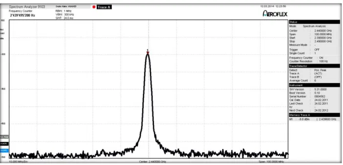
2.1 CW Mode
The MTK supports continuous Carrier Wave (CW) transmission. This signal can be used to verify carrier center frequency, RF power output, and equalization across the spectrum. Normally IEEE 802.15.4 transmitters use DSSS and O-QPSK modulation with a 500kHz deviation. To create a CW waveform using the IEEE 802.15.4 transmitters the symbols are all sent in the lower sideband with a -500kHz offset. For example a setting of CH18, 2440.0MHz will have a peak at 2439.5MHz.
2.2 PRBS Mode
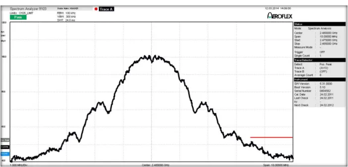
The MTK also supports continuous Modulated Carrier mode. A Pseudo-Random Binary Sequence (PRBS) is transmitted using O-QPSK modulation. This format is useful for Power Spectral Density measurements and verification of suppression in restricted bands.
Figure 2-2. PRBS Mode CH25 Restricted Band Test
Figure 2-3. PRBS Mode CH26 PLL_TX_FLT Enabled
Figure 2-2 and Figure 2-3 show ATmega256RFR2 passing Restricted Band tests in the high channels. The horizontal red line on the right is the -54dBµV @ 3m limit, in the 2483.5 to 2500MHz band, set by FCC regulations
3
User Interface
The MTK uses UART Channel 1 of the ATmega256RFR2. The default serial port settings are Baud=38400, DataBits=8, StopBits=1, Parity=None, FlowControl=None.
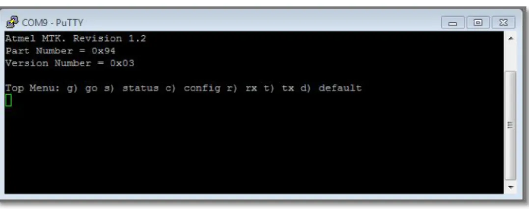
Figure 3-1. MTK Terminal Display
The MTK includes a menu driven interface that can be run using a serial terminal or automated script. The interface returns to the Top Menu when the system is idle. At the top level there are several choices:
Top Menu g) go
This starts the CW or PRBS tests. Pressing any key will stop the test and turn the transmitter off.
s) status
This choice dumps the DUT settings to the terminal. The channel, power, modulation mode, and battery voltage are displayed. This choice is used to verify the DUT configuration before testing.
c) configure
This selection calls a sub-menu to configure the DUT.
Config Submenu
c) channel. Channels 11 through 26.
p) power. Tx power levels +3dBm to -17dBm.
m) modulation. CW and PRBS modes.
q) quit. Return to Top Menu.
r) rx
Enable receiver for one-shot test.
t) tx
Transmits one packet.
d) default
4
DUT Default Settings
Settings are preserved as long as the DUT is active. Power cycling, resetting the device, or selecting the d) default choice will reload the DUT with the default settings:
TX Channel = CH18 2440MHz TX Power = 0dBm
TX Modulation = CW
5
Submenus
The channel, power, and modulation submenus are straightforward. All submenus include a q) quit choice that aborts the selection process and take the user back to the Top Menu. When a menu choice sequence has been completed the MTK will cycle back to the Top Menu.
6
Error Messages
If the user makes an incorrect selection the warning “QRM Bad Key” is thrown, the choice sequence is aborted and the user is taken back to the Top Menu.
7
Interacting with automated scripts
With high-speed automation routines the “Top Menu:” string can be used for flow control and verification that the MTK firmware is IDLE and ready for commands. For consistent message handling by automated scripts all responses from the MTK are strings terminated with \r \n and all menus and submenu choices take only one keystroke as input.
8
One-Shot Test
The One-Shot test is included for functional verification of the PHY. The One-Shot test uses the Atmel® LwMesh [1] to implement a simple point-to-point network between two devices running the MTK firmware. The PANID 0x5558 is used. The Transmitter is Address 1. The Receiver is Address 0. Normal 250kbps O-QPSK modulation is used. (CW and PRBS settings are ignored.) The test payload is “QRV ATMEL MTK”, 13 bytes. The NWK header used by the LwMesh is 7 bytes. This result in a 20 byte (octet) PDSU recommended for receiver sensitivity evaluation in Section 6.1.7 of the IEEE 802.15.4 spec [2].
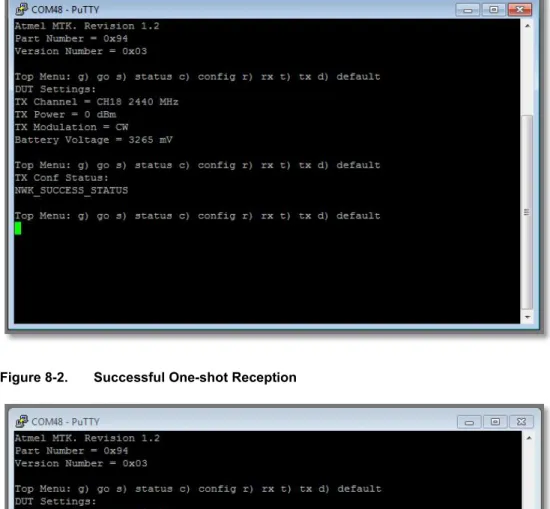
To run the test make sure the channel settings on both devices match. Start the receiver first with the r) rx command. The Receiver will monitor the channel for the first packet it observes (including broadcast messages). Next send the packet by selecting the t) tx choice on the “Gold” unit. The Transmitter will display transmission status returned by appDataConf(). The Receiver will display the payload and RSSI returned by appDataInd() when a packet is received. On-air packet behavior can be observed using the Atmel Wireshark Packet Analyzer
Figure 8-1. Successful One-shot Transmission
Figure 8-2. Successful One-shot Reception
9
Know Issues
The one-shot test is a compromise; one-shot was chosen to avoid network configuration issues, code space consumption and feature creep on the DUT. Test protocols requiring larger sample populations, parametric variation and statistical analysis can be managed at higher levels using test scripts and post-processing. The LwMesh uses CSMA and AACK. These may have odd side effects in point-to-multi-point networks. To avoid confusion it is recommended to use SDMA or just power one DUT at a time.
The MTK is released for the ATmega256RFR2 Xplained PRO platform. This is a low cost platform and is not calibrated. Power outputs can be several dBm lower than the datasheet specs. Test systems also add cable losses and other attenuating elements. Furthermore, power settings in the transmitter and the RF power detector (used to measure RSSI) are not precisely linear. Characterization of “Gold” units with calibrated instruments is strongly recommended.
10 Python Script
Mtk_driver.py is a short python script is included as a starting point for Test Engineers. This was written using python 2.7.
11 References
[1] AVR®2130: Lightweight Mesh Developer Guide
[2] IEEE Std 802.15.4™-2006
[3] FCC CFR-2009-title47-vol1-part15
12 Appendix
12.1 IEEE 802.15.4 Relevant Sections
6.1.7, 6.1.2.1, 6.5 6.9 and Appendix E and Appendix F
12.2 Minimum Product Performance Targets
6.5.3.1 Transmit power spectral density (PSD) mask (-20dBc and-30dBm f > fc ±3.5MHz 6.5.3.3 Receiver Sensitivity -85dBm or better (using 6.1.7 packets)
6.5.3.4 Anti-jam and ACPR 6.9.3 Error Vector Magnitude 35%
6.9.4 Transmit carrier center frequency tolerance ±40PPM (~±100kHz) Across temperature, voltage and aging 6.9.5 Transmit Power -3dBm
6.9.6 Receiver maximum input level -20dBm Line power ≤5mA Active mode and 14.5mA in Tx
12.3 Regulatory Testing
15.35 definitions Quasi-peak 100k bw < 1G and average 1MHz bw > 1G
15.205 restricted bands; 2483.5-2500 and 4.5-5.15GHz 500µV/m @ 3m (+54dBµV) (-41dBm/MHz ERP average using 1MHz detector, absolute limit)
15.209 general rule spurious emissions -20dBc
13 Revision History
Doc Rev. Date Comments
Atmel Corporation 1600 Technology Drive, San Jose, CA 95110 USA T: (+1)(408) 441.0311 F: (+1)(408) 436.4200 │ www.atmel.com © 2014 Atmel Corporation. / Rev.:Atmel-42286A-WIRELESS-Wireless-Manufacturing-Test-Kit-ApplicationNote_042014.
Atmel®, Atmel logo and combinations thereof, AVR®, Enabling Unlimited Possibilities®, and others are registered trademarks or trademarks of Atmel Corporation or its
subsidiaries. Other terms and product names may be trademarks of others.
DISCLAIMER: The information in this document is provided in connection with Atmel products. No license, express or implied, by estoppel or otherwise, to any intellectual property right is granted by this document or in connection with the sale of Atmel products. EXCEPT AS SET FORTH IN THE ATMEL TERMS AND CONDITIONS OF SALES LOCATED ON THE ATMEL WEBSITE, ATMEL ASSUMES NO LIABILITY WHATSOEVER AND DISCLAIMS ANY EXPRESS, IMPLIED OR STATUTORY WARRANTY RELATING TO ITS PRODUCTS INCLUDING, BUT NOT LIMITED TO, THE IMPLIED WARRANTY OF MERCHANTABILITY, FITNESS FOR A PARTICULAR PURPOSE, OR NON-INFRINGEMENT. IN NO EVENT SHALL ATMEL BE LIABLE FOR ANY DIRECT, INDIRECT, CONSEQUENTIAL, PUNITIVE, SPECIAL OR INCIDENTAL DAMAGES (INCLUDING, WITHOUT LIMITATION, DAMAGES FOR LOSS AND PROFITS, BUSINESS INTERRUPTION, OR LOSS OF INFORMATION) ARISING OUT OF THE USE OR INABILITY TO USE THIS DOCUMENT, EVEN IF ATMEL HAS BEEN ADVISED OF THE POSSIBILITY OF SUCH DAMAGES. Atmel makes no representations or warranties with respect to the accuracy or completeness of the contents of this document and reserves the right to make changes to specifications and products descriptions at any time without notice. Atmel does not make any commitment to update the information contained herein. Unless specifically provided otherwise, Atmel products are not suitable for, and shall not be used in, automotive applications. Atmel products are not intended, authorized, or warranted for use as components in applications intended to support or sustain life.