Design and Analysis of a Propeller Shaft in CAE tool and ANSYS
Gara Bharat Kumar#1, M Manoj#2, P.Satish Reddy#3 Scholar of Master of Technology, Asst Professor, Assoc Professor
Dept of Mechanical Engineering, Prasiddha College of Engg & Tech, Anathavaram [email protected],[email protected],[email protected]
Abstract:
A Propeller Shaft is a device on which a propeller is attached to and transfers the power from the engine to the propeller. In the design of automobiles, the industry is exploiting in order to obtain reduction of weight without significant decrease in vehicle quality and reliability. This is due to the fact that the reduction of weight of a vehicle directly impacts its fuel consumption. Particularly in city driving, the reduction of weight is almost directly proportional to fuel consumption of the vehicle. A Propeller Shaft is a longitudinal drive shaft used in vehicles where the engine is suited at the opposite end of the vehicle to the drive wheels. A propeller shaft is an assembly of one or more tubular shaft connected by universal, constant velocity or flexible joints. Thus, in this project work the propeller shaft of a vehicle was chosen and analyzed by replacing it with different materials
Keywords: Propeller Shaft, catiav5, ANSYS, Steel-Reference Material, Boron, Kevlar, Aluminum, Glass, Carbon, analysis
I. INTRODUCTION
In the process of designing a vehicle, one of the most important objectives is the conservation of energy and the most effective way to obtain this goal is the reduction of weight of the vehicle. There is almost a direct proportionality between the weight of the vehicle and its fuel consumption, particularly in city driving. The automotive industry is exploiting composite material technology for structural component construction in order to obtain reduction of weight, without decrease in vehicle quality and reliability. Properties can be tailored to increase the torque they carry as well as the rotational speed at which they operate. In this project, the conventional propeller shaft has been replaced with different types of material to carry out a comparative analysis, thus determining the most suitable replaceable material
II. AIM AND SCOPE OF THE WORK:
The project aims to reduce the weight of the propeller shaft assembly by using different materials. For this project work, the drive shaft of a car was chosen. The modeling of the propeller shaft assembly was done using Catia V5. A Leaf spring has to be designed to meet the stringent design requirements for automobiles. A comparative study of five different materials was conducted to choose the best-suited material. Steel (SMC 45) was chosen for reference and the rest of the five different materials were analyzed. The analysis was carried out using ANSYS 10.0 Workbench for the following materials.
The first was Steel (SM C 45) which was used for reference purpose
Two Composites Boron Kevlar
And a combination of
Aluminum Glass Carbon
The standard material properties of steel are given as
follows
Table-1: Mechanical Properties of Steel (SMC45)
Material Properties for Boron
Density = 2600 kg/m3 ,Young’s Modulus = 3 Gpa, Poisson’s Ratio = 0.21
Material Properties for Kevlar
Density = 1440 kg/m3 ,Young’s Modulus = 130 Gpa ,Poisson’s Ratio = 0.34
Material Properties for Aluminum
Density = 2700 kg/m3, Poisson’s Ratio = 0.35 Young’s Modulus = 70 Gpa
Material properties for Glass
Density = 2540 kg/m3, Young’s Modulus = 72.4Gpa, Poisson’s Ratio = 0.34
Material Properties for Carbon Density = 1800 kg/m3
Poisson’s Ratio = 0.2 Young’s Modulus= 225 Gpa
IV. DESIGN CONSIDERATION FOR A
PROPELLER SHAFT Description of the Problem:
The fundamental natural bending frequency for passenger cars, small trucks, and vans of the propeller shaft should be higher than 6,500 rpm to avoid whirling vibration and the torque transmission capability of the Propeller shaft should be larger than 3,500 Nm. The Propeller shaft outer diameter should not exceed 100 mm due to space limitations. The Propeller shaft of transmission system is to be designed optimally for following specified design requirements as shown in Table.
S. No Name Notation Units Value
1 Ultimate Torque
Tmax N-m 3500
2 Max Speed Nmax Rpm 6500 3 Max Diameter
D mm 90
Propeller Shaft Design Formulae for Calculations:
Deflection:
YMax=
E = Young’s Modulus of Steel (SMC 45)
L = Length of the shaft
I = Moment of inertia
Maximum Shear Stress:
ƮMax=
T = Torque
Ro = Outer Radius
ƮMax= Shear Stress
Maximum Von-Misses Stress:
T = Torque
S.no parameters values
1 Outer Radius (Ro) 0.02m
2 Inner Radius (Ri) 0.01m
do = Outer Diameter
I = Moment of inertia
Design Calculations
For the hollow shaft, Let
Ro= 0.04 m ; Ri= 0.02 m ; l = 0.5 m ; E = 207e9 pa
and Torque=3500 Nm
Where Ro= Outer Radius
Ri= Inner Radius
l = Length of the shaft
E = Young’s Modulus of Steel (SM45C)
T = Applied Torque
Deflection = YMax= =
= 0.0179 m
Then:
Maximum Shear Stress:ƮMax=
=
=
= 2.9708 e 8 Pa
Maximum Von-Misses Stress:
=
=
= 594178454.2
= 5.9417 e 7 Pa
V. STRUCTURAL ANALYSIS OF
PROPELLER SHAFT
In this work propeller shaft is selected for structural analysis using ANSYS. The various materials using finite element analysis software ANSYS 10.0 CLASIC
MODELING OF PROPELLER SHAFT IN CATIA V5:
The propeller shaft is designed by required dimensions into the modeling software Catia V5. The geometry of the propeller shaft is designed in Catia V5 is imported to the analysis software in the IGES format.
The designed propeller shaft is below
Fig 5.1 Propeller Shaft
Propeller Shaft Model and Mesh
STRUCTURAL ANALYSIS WITH DIFFERENT MATERIALS
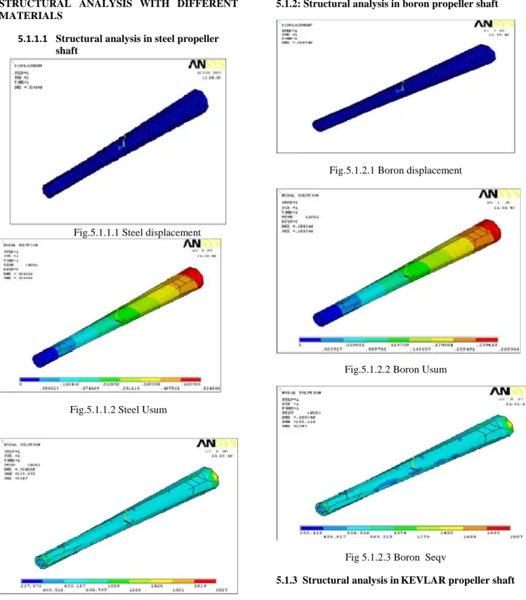
5.1.1.1 Structural analysis in steel propeller shaft
Fig.5.1.1.1 Steel displacement
Fig.5.1.1.2 Steel Usum
Fig.5.1.1.3 Steel Seqv
5.1.2: Structural analysis in boron propeller shaft
Fig.5.1.2.1 Boron displacement
Fig.5.1.2.2 Boron Usum
Fig 5.1.2.3 Boron Seqv
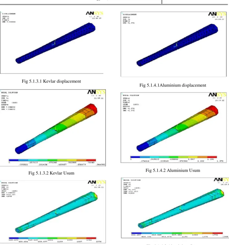
Fig 5.1.3.1 Kevlar displacement
Fig 5.1.3.2 Kevlar Usum
Fig 5.1.3.3 Kevlar Seqv
5.1.4 Structural analysis in Aluminium propeller shaft
Fig 5.1.4.1Aluminium displacement
Fig 5.1.4.2 Aluminium Usum
Fig 5.1.4.3 Aluminium Seqv
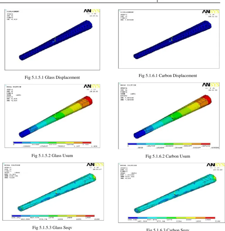
Fig 5.1.5.1 Glass Displacement
Fig 5.1.5.2 Glass Usum
Fig 5.1.5.3 Glass Seqv
5.1.6 Structural analysis in carbon propeller shaft
Fig 5.1.6.1 Carbon Displacement
Fig 5.1.6.2 Carbon Usum
Fig 5.1.6.3 Carbon Seqv
VI RESULTS AND DISCUSSIONS:
S.N o
MATERI AL
DEF LEC TION Max
STRESS Max
STRESS Min
1 STEEL 0.524
01
2017 237.875
2 BORON 0.269
35
2097 415.505
3 KEVLAR 0.844
3
1976 226.193
4 ALUMIN
IUM
1.571 1966 222.657
5 GLASS 1.424 2106 256.657
6 CARBON 0.454 2106 256.541
VI. MODAL ANALYSIS OF PROPELLER SHAFT
6.1 STEEL:
S.NO FREQUENCY DEFLECTION
MAX
1 682.335 592.787
2 690.768 591.99
3 4191 613.97
4 4259 615.107
5 11282 590.285
Mode1
Mode2
Mode3
Mode5
6.2 BORON
S.NO FREQUENCY DEFLECTION
MAX
1 1582 1013
2 1605 1011
3 9727 1050
4 9915 1052
5 2645 1055
Mode1
Mode2
Mode3
Mode5
6.3 KEVLAR:
S.NO FREQUENCY DEFLECTION
MAX
1 1250.4 1362
2 1264.1 1361
3 7679.9 1411
4 7786.3 1413
5 20414 1342
Mode1
Mode2
Mode3
Mode5
6.4 ALUMINIUM:
S.NO FREQUENCY DEFLECTION
MAX
1 671.605 994.756
2 678.653 993.799
3 4125 1030
4 4179 1032
5 10930 979.541
Mode1
Mode2
Mode3
Mode4
6.5 GLASS:
S.NO FREQUENCY DEFLECTION
MAX
1 694.105 1025
2 704.157 1023
3 4268 1062
4 4351 1064
5 11611 1068
Mode1
Mode2
Mode3
Mode4
6.6 CARBON:
S.NO FREQUENCY DEFLECTION
MAX
1 1454 1217
2 1475 1215
3 8958 1262
4 9112 1264
5 24314 1269
Mode1
Mode2
Mode3
Mode4
Mode5
VII CONCLUSION
machine, which employs Propeller shafts, in general. This was achieved by reducing the weight of the Propeller shaft with the use of different materials. The Propeller shaft of a vehicle was chosen for determining the dimensions, which were then used for creating a model in Catia V5. Being a complex assembly of a number of parts, it had to be analyzed only for Propeller shaft in ANSYS 10. A total of five materials were chosen for the comparative analysis, including steel, which was used for reference.
Taking into consideration the weight saving, deformation, shear stress induced and resonant frequencies it is observed that Boron has the most encouraging properties to act as the replacement for steel out of all the materials.
VIII REFERENCES:
1. A.K. Kaw, Mechanics of Composite Materials, CRC Press, 1997.
2. Dwayne A., “Composites and Advanced
Materials” (Centennial of Flight
Commemoration Act Public Law 105-389 105thCongress (November 13, 1998)).
NASA. U.S. Centenial of Flight Commission.(2003).
3. Mallick, P Newman, K. composite materials tech. hanser publishers inc (1990).
4. Vijayarangan, S., Rajendran, I. Optimal Design of a Composite Leaf Spring Using Genetic Algorithm Computers and Structures 79 2001: pp. 1121–1129.