STRUCTURAL ANALYSIS OF CONNECTING ROD OF
SEPARATOR DRIVING MECHANISM WITH ECCENTRIC
BELONGING TO TECHNICAL EQUIPMENT FOR HARVESTING
MISCANTHUS RHIZOMES
SORICĂ C.1), MARIN E.1), SORICĂ E.1), 1)INMA Bucharest;
E-mail:[email protected]
Keywords:structural analysis, connecting rod, optimization, separator with eccentric
ABSTRACT
Article presents a structural analysis of connecting rod of driving mechanism of separator with eccentric belonging to technical equipment of harvesting rhizomes ofMiscanthus, where the equivalent tension values in structure and resulting relative movement are determined..
Within the mechanism which drives the separator with eccentric, the connecting rod of quadrilateral mechanism is subject to tensile strength and compression.Structural analysis of connecting rod belonging to eccentric separator has allowed the optimization of its construction and operation.
INTRODUCTION
For establishing a new culture, using a high quality material is a prerequisite and therefore, rhizomes harvesting represents one of the most important operations [2], [3], [8], [9], [10] with major influence on the quality of seedling material.
Technical equipment of harvesting Miscanthus rhizomes (fig. 1) performs the operation of extraction of Miscanthus rhizomes out of the soil and their separation of earth. Process of displacement consists in soil deep loosening without overturning it, destroying the connections between soil and rhizomes and pushing them up to the oscillating grates; the grates separate by sieving the rhizomes of impurities and earth and let them in the furrow, after which they are loaded into the transport means.Equipment comprises a separator with eccentric driven by a quadrilateral mechanism made of a connecting rod, a crank and a working beam, represented by separator’s rods.
The separator with eccentric is driven by a hydraulic engine coupled at the tractor’s hydraulic installation.
Fig. 1 – Equipment for harvesting the Miscanthus rhizomes[11]
Table 1 Den.
no. Characteristic MU Value
1. Type of equipment - carried
2. Type of displacing plough share - plane inclining blade
3. Driving method of separator with eccentric - hydraulic
4. Separator oscillation frequency Hz 4.16
5. Amplitude of separator’s oscillations mm 26
6. Power of tractor working in aggregate HP 70...80
7. Working width m 1.2
8. Working depth cm max. 25
9. Clearance mm 350
Separator with eccentric (fig. 2) is designed to clean the earth by shaking and transport the Miscanthus rhizomes displaced to the machine’s rear part. It comprises two oscillating grates that take over the soil displaced together with the rhizomes and an oscillating mechanism with eccentric that achieves an optimum vibrating effect so that the soil detaches from rhizomes and fall on the ground between the grate holes.
Fig. 2 – Separator with eccentric[11]
MATERIAL AND METHOD
Within the driving mechanism of separator with eccentric, the quadrilateral mechanism connecting rod is subject to strain forces if the separator’s angular speed (mechanism connecting rod) has negative sign ω3< 0 and compression, if the angular speed of separator has positive sign ω3> 0.
Following the kinetostatics analysis, reactions of each rotation coupling of the mechanism have been obtained. Therefore, it has found that the maximum tensile strength is manifested for the position of mechanism at which the crank rotation angle is φ1= 4.538 rad. For this position, the tensile force acting on point B has the value of R12=2105,829 N and tensile force acting on point C has the value of R32=1980,821 N. [11]
Maximum compression forces become manifest for the mechanism position at which the crank rotation angle is φ1 = 1.221 rad. For this position, the compression force acting on point B has the value of R12=1095,24 N and, the compression force acting on point C has the value of R32=2191,273 N.
Taking into account these strains, it has found that the maximum stress is present when stretching for the crank rotation angle of φ1 = 4.538 rad. and structural analysis willbe based on this strain.
Geometry of connecting rod is generated in SolidWorks program and shown in figure 4.
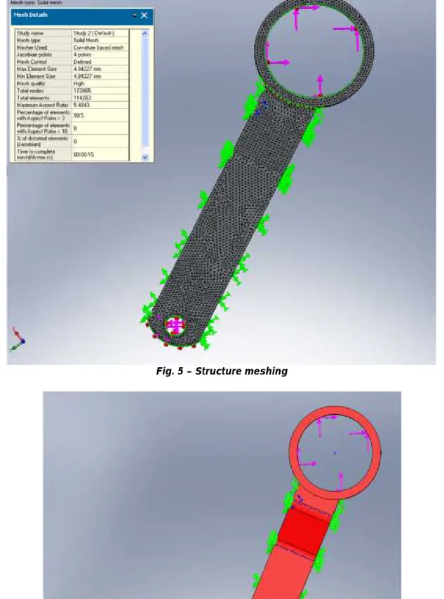
Fig. 4 – Connecting rod geometry
Structure is made of two solid components considered to be totally connected and working together as a unique body. Meshing is made with elements of 3D type (fig. 5) and contains 114203 elements and 172865 nodes.
Type of structural analysis is the linear static elastic analysis and therefore the material out of which is made the structure is an elastic-linear, homogeneous and isotropic material. The connecting rod position comparing to coordinates system is that at which it is placed at the maximum stress moment.
Structure is loaded in the two bearings, each bearing being acted by a tensile strength with two components on axes OX and OY (fig. 6).
Structure is made of steel with the following material constants: - density 7800 kg/m3;
- limit strain 220,59 MPa;
RESULTS AND DISCUSSIONS
Analysis results have consisted in indicating the values of equivalent tension in structure and relative movement resulted. Relative movement resulted represents an important parameter of structure deformation. For the agricultural machines designed to soil works, a high value of structure deformation can determine an inappropriate quality of agricultural works.
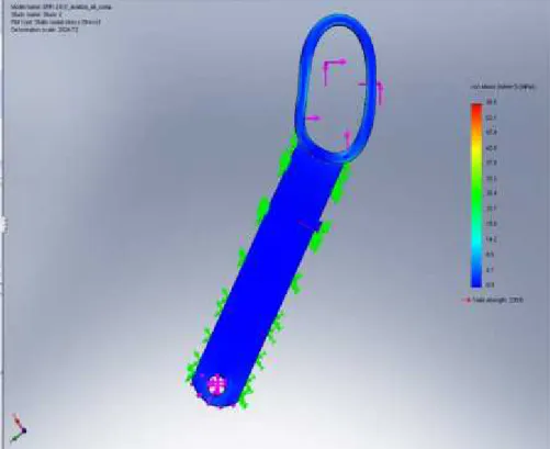
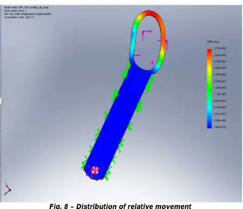
Equivalent tension [1], [4], [5], [6], [7], is the measure of tension in metallic structures that is used for comparing it to the limit strain related to each it must be smaller, in order to operate in the elastic field. Distribution of equivalent tension in structure is shown in figure 7, and that of relative movement is shown in figure 8.
Fig. 7 – Distribution of equivalent tension in structure
Main results of linear static analysis are synthetized in table 2.
Table 2 Equivalent tension,
[MPa]
Relative movement resulted (deformation), [mm]
Fig. 8 – Distribution of relative movement
CONCLUSIONS
Due to the fact that maximum equivalent tension (56.8 MPa) is much smaller than the limit stretching tension of material (220.59 MPa), the whole structure works within the linear elastic domain;
In conditions considered, the most stressed area is in the joint connected to the crank that drives the mechanism, to the strain force resultant direction.(fig. 7);
Maximum relative movement (fig. 8) takes place in the joint connected to the crank that drives the mechanism, its maximum value being of 0.027 mm;
For the structure loaded the minimum value of safety coefficient is of 3.88, value which is appropriate to joint structures of agricultural machines.
REFERENCES
1. Ahrendts, J. and &, 1995 –Engineer Manual (Hutte. Die Grundlagen der Ingineurwissenschaften), EdituraTehnică Publishing, Bucharest;
2. Atkinson, C. J., 2009 – Establishing the perennial energy crops in Great Britain: A review of current options of Miscanthus propagation, biomass and bioenergy, Volume 33, No.5, Pg.752–759.
3. Boersma, N. N., Heaton, E. A., 2014 – Method of propagation affecting Miscanthus- x morphology of giganntic development, Industrial cultures and products, Volume 57, June 2014, Pg.59–68.
7. Marin, C., 1997 – Materials resistance and elements of elasticity theory, EdituraBiblioteca Publishing, Târgovişte;
8.O’Flynn, M. G., Finnan, J. M., Curley, E. M., McDonnell, K. P., 2014 –Diminishing the crops damaging and yield losses in the last harvesting period of Miscanthus × giganteus, Researches on soil and harvest, Volume 140, Pg.8–19;
9. Sorică, C., Voicu, E., 2009 – Development of a technology capitalizing the Miscanthus rhizomes in order to make more efficient the establishment of this energy culture, Contract no. 15N/27.02.2009, Project: PN 09-15.02.01;
10. Sorică, C., Voicu, E., Manea, D., 2009 – Technology for promoting in Romania the energy plant Miscanthus as a renewable source for increasing work competitiveness and safety, in INMATEH Journal No. 29 (2009-III), pg. 19-26, Bucharest, ISSN 1583-1019, http://www.inma.ro/inmateh;
![Fig. 1 – Equipment for harvesting the Miscanthus rhizomes [11]](https://thumb-us.123doks.com/thumbv2/123dok_us/8070510.2137799/1.892.338.548.841.1023/fig-equipment-harvesting-miscanthus-rhizomes.webp)