ADMINISTRATION
GUIDE
Linksys Voice System
SPA9000 IP Telephony SystemSPA400 PSTN VoIP Gateway with Integrated Voice Mail Server SPA9x2 IP Phones
Preface . . . vi
Document Audience vi
Firmware vii
Document Purpose and Contents viii
Document Conventions ix
Related Documentation ix
Finding Information in PDF Files xi
Finding Text in a PDF xi
Finding Text in Multiple PDF Files xi
Online Resources xiii
Copyright and Trademarks xiii
Technical Support xiii
Chapter 1: Getting Started . . . . 13
Introduction to the Linksys Voice System 13
SPA9000 IP PBX 14
SPA400 SIP-PSTN Gateway and Voicemail Server 14
SPA900 Series IP Phones and Accessories 14
Deployment Scenarios 15
Deploying the LVS with PSTN Access and Local Voice Mail 16
Deploying the LVS with ITSP Service Only 17
Deploying the LVS with ITSP Service, PSTN Access and Local Voice Mail 18 ITSP Service, PSTN and ISDN Access and Local Voice Mail 19
Initial Installation, and Configuration 20
Chapter 2: Basic Administration of the SPA9000 . . . . 21
Upgrading Firmware for the SPA9000 21
Connecting to the SPA9000 Administration Web Server 24
Saving or Discarding Changes SPA9000 24
Access Levels 25
Setting Passwords for User and Administrator Accounts 25
Configuring Basic Settings 26
Setting Up the WAN Connection for the SPA9000 26
Setting the Date and Time 27
Configuring Daylight Saving Time 27
SPA9000 Ethernet Port 28
LAN and Application Guidelines 28
Configuring Multicast Addressing and Group Paging 29
Collecting System Logs and Debug Information 31
Viewing Information about the SPA9000 33
Viewing Information about Client Stations 33
Using the Interactive Voice Response Unit 33
Using the IVR Menu 34
Entering a Password through the IVR 37
Chapter 3: Configuring the SPA9000 for ITSP Interoperability . . 39
About LVS and SIP 39
Network Address Translation (NAT) and Voice over IP (VoIP) 40
NAT Mapping with SIP-ALG Router 40
Configuring NAT Mapping with a Static IP Address 41
Configuring NAT Mapping with STUN 42
Firewalls and SIP 43
Configuring SIP Timer Values 44
Chapter 4: Configuring Phone Lines and Calling Routing Behavior 45
Configuring SPA9000 FXS Ports 45
Configuring Line Interfaces on the SPA9000 46
Configuring a Line Interface for ITSP Service 46
Configuring a Line Interface for a SPA400 (PSTN or Voice Mail) 48
Configuring Call Capacity for a Line Interface 51
Configuring Dial Plans 52
How the Dialed Digits are Processed 53
Digit Sequences 53
Digit Sequence Examples 55
Acceptance and Transmission the Dialed Digits 56
Editing the System Dial Plan 57
Entering a Phone Dial Plan 58
Entering the Line Interface Dial Plan 59
Setting the Timers for the Dial Plan 59
Managing the Line Selection for Outbound Calls 63
Line Availability 63
Configuring a Call Routing Rule 63
Entering a Call Routing Rule 65
Managing Caller ID Settings for Outgoing Calls 65
Managing Inbound Calls with the Contact List 66
Routing an Inbound Call to the Auto Attendant 66
Routing an Inbound Call to a Receptionist or Client Stations 66
Example Contact List Rules 66
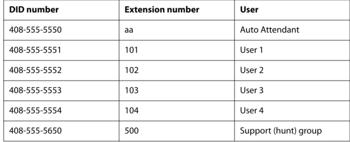
Supporting Multiple DID Numbers Per Line Interface 68
An incoming call to the main number is answered by the Auto-Attendant, while calls to the other nine DID numbers are routed to dedicated private extensions. 69 Supporting Direct Inward Dialing to Phone Extensions 69
Entering a Contact List Rule 70
Call Forwarding Support on SPA9000 71
Call Transfer Support on SPA9000 72
Call Forward Bridge Mode 72
Call Transfer Bridge Mode 72
Managing Inbound Calls with Hunt Groups 73
Hunt Group that Rings All Stations Simultaneously 73
Hunt Group that Rings Stations Individually 75
Managing Inbound Calls with Shared Line Appearances 77
About Shared Line Appearances 77
Chapter 5: Administering the SPA400 and Voice Mail Service . . 80
Connecting to the SPA400 Administration Web Server 80
Configuring the SPA400 Network Connection 81
Saving or Discarding Changes on the SPA400 82
Managing Access to the SPA400 Web-Based Configuration Utility 83
Configuring a SPA400 to Interoperate with the SPA9000 85
Configuring a SPA400 for PSTN Access 87
Configuring a SPA400 for Voice Mail Service 87
Voice Mail Capacity 88
Configuring Local Voice Mail Service on a SPA400 88
Setting Up Voice Mail on Each Station 90
Enabling Remote Voice Mail Access (Optional) 93
Managing the Voice Mail Messages on the USB Key 94
Enabling Debugging on the SPA400 95
Chapter 6: Configuring Music on Hold . . . . 97
Using the Internal Music Source for Music On Hold 97
Using the Internal Music Source 97
Changing the Music File for the Internal Music Source 98
Restoring the Original Music File 98
Configuring a Streaming Audio Server 99
Using a Streaming Audio Server 99
Using the IVR with an SAS Line 100
Example SAS with MOH 100
Configuring the Streaming Audio Server 101
Chapter 7: Configuring the LVS Auto-Attendant . . . 103
How the Auto Attendant Works 103
Working with the Auto Attendant Greetings 104
Using Pre-Recorded Prompts 104
Recording an Auto Attendant Prompt 105
Downloading Prompts 107
Writing an Auto Attendant Script 108
An Introduction to XML Scripting Grammar in AA Script Examples 109
Elements of XML Scripting Grammar 111
Auto Attendant XML Instructions Set 113
Entering an Auto Attendant Script 115
Configuring the DayTime, NightTime and Weekend/Holiday Auto Attendants 116
Configuring Dial Plans for the Auto Attendant 117
Chapter 8: Localization . . . 118
Requirements for Localization 118
Localizing the SPA9000 Auto Attendant Prompts 118
Local Time Configuration 120
Configuring the SPA9000 and SPA9xx Call Progress Tones 120
Localizing the SPA400 Voice Mail Prompts 125
Localizing the SPA400 Call Disconnect Tones 126
Localizing the SPA400 Caller ID Method 128
Appendix A: Advanced Topics in LVS Administration . . . 130
Technology Background 130
Session Initiation Protocol 130
SPA9000 Media Proxy 132
Using the SPA9000 with a Firewall or Router 133
SPA9000 Architecture 134
SIP-NAT Interoperation 135
Determining Whether the Router Uses Symmetric or Asymmetric NAT 136
Advanced Call Control and Routing 137
Configuring Vertical (Supplementary) Service Codes 137
Managing the Outbound Call Routing Groups 139
Configuring Outbound Call Codec Selection Codes 141
Advanced Topics for SPA400 Voice Mail Service 141
How Voicemail Works 142
Checking Voicemail from an External Number 142
Depositing Voicemail 143
Subscribing to Voicemail Notification 144
Remote Provisioning Features 145
Using Configuration Profiles 145
Client Auto-Configuration 146
Manual Client Configuration 147
Client Registration 149
Using the Upgrade URL 150
Using the Resync URL 151
Using the Reboot URL 151
Appendix B: SPA9000 Field Reference . . . 152
Router Tab 152
Status page 152
Wan Setup page 153
Lan Setup page and Application page 156
Voice tab 156
Info page 156
System page 159
SIP Page 160
Provisioning page 176
Regional page 176
FXS 1/2 page 189
Line 1/2/3/4 page 196
Appendix C: SPA400 Field Reference . . . 203
Setup 203
Basic Setup 203
SPA9000 Interface 204
Voice 205
Voicemail Server 208
Voicemail Users 209
Administration 209
Management 209
Factory Default 210
USB Setting 210
Firmware Upgrade 210
Reboot 210
Status 211
Set Log Level 212
Tone 212
Appendix D: Warranty Information . . . 214
Limited Warranty 214
Exclusions and Limitations 214
Obtaining Warranty Service 215
Technical Support 215
Appendix E: Regulatory Information . . . 216
Federal Communications Commission Interference Statement 216Industry Canada Statement 216
Règlement d’Industry Canada 216
EC Declaration of Conformity (Europe) 217
User Information for Consumer Products Covered by EU Directive 2002/96/EC on Waste
Electric and Electronic Equipment (WEEE) 217
Appendix F: Safety Information . . . 224
Meaning of the Warning Symbol 224
General Safety Information 224
Power Safety Information 225
Appendix G: Software License Agreement . . . 227
Software in Linksys Products: 227
Software Licenses: 227
Schedule 1 Linksys Software License Agreement 227
Schedule 2 229
Schedule 3 234
Appendix H: Contacts . . . 237
Appendix I: Acronyms . . . 238
Appendix J: Glossary . . . 241
Preface
The Linksys Voice System Administration Guide is intended to help VARs and Service Providers to manage and configure the Linksys Voice System (LVS). This preface provides helpful
information about this guide and other resources that are available to you. Before you begin to use this guide, refer to the following topics:
• ”Document Audience,” on page vi
• ”Document Purpose and Contents,” on page viii • ”Document Conventions,” on page ix
• ”Related Documentation,” on page ix
• ”Finding Information in PDF Files,” on page xi • ”Online Resources,” on page xiii
• ”Copyright and Trademarks,” on page xiii
Document Audience
This document is written for the following audience:
• Service providers offering services using LVS products • VARs and resellers who need LVS configuration references
• System administrators or anyone who performs LVS installation and administration
Note This guide does not provide the configuration information required by specific service providers. Please consult with the service provider for specific service parameters.
Firmware
This guide supports the following firmware releases. The installed firmware must be at least the indicated in the table below.
Product Firmware Version
SPA9000 5.1.9
SPA400 1.0.1.4
SPA922/SPA942 5.2.5
SPA962 5.2.8
SPA901 5.1.5
Document Purpose and Contents
This document provides information that an administrator needs to configure the Linksys Voice System, which typically consists of a SPA9000 IP PBX, one or more SPA900 Series IP phones, and the optional SPA400 PSTN gateway and voice mail server. This guide focuses primarily on the tasks that an administrator performs to configure a SPA9000 with the SPA9000 administration web server.
NOTE: This guide does not cover initial installation and configuration, SPA900 Series phone configuration, the Setup Wizard, or provisioning. See ”Related Documentation,” on page ix. The information in this guide is organized into the following chapters and appendices:
Chapter 1, "Getting Started." This chapter introduces you to the Linksys Voice System (LVS) by describing the components and presenting several deployment scenarios.
Chapter 2, "Basic
Administration of the SPA9000."
This chapter introduces you to basic administrative tasks using the SPA9000 administration web server and the Interactive Voice Response Unit.
Chapter 3, "Configuring the SPA9000 for ITSP
Interoperability"
This chapter provides configuration details for the purpose of helping you to ensure that your infrastructure properly supports the LVS.
Chapter 4, "Configuring Phone Lines and Calling Routing Behavior"
This chapter describes many features that you can configure on the SPA9000 to ensure smooth handling of all inbound and outbound calls, and ease of use.
Chapter 5, "Administering the SPA400 and Voice Mail Service"
This chapter guides you through the process of
configuring and managing the SPA400 for PSTN access and voice mail service.
Chapter 6, "Configuring Music on Hold"
This chapter explains how to configure Music on Hold using either a music file or streaming audio.
Chapter 7, "Configuring the LVS Auto-Attendant"
This chapter describes how to configure the LVS Auto Attendant using the IVR, and XML scripting.
Chapter 8, "Localization" You can localize your LVS with the language files, tones, and ring patterns that are appropriate for your region. Appendix A, "Advanced Topics
in LVS Administration"
This appendix provides technical information that is useful to individuals who want a better understanding of how the LVS works.
Appendix B, "SPA9000 Field Reference"
This appendix describes the fields on each page of the SPA9000 administration web server.
Appendix C, "SPA400 Field Reference"
This appendix describes the fields on each page of thes of the SPA400 administration web server.
Document Conventions
The following are the typographic conventions used in this document.
Related Documentation
This LVS Administration Guide is part of a complete suite of documentation that is available to assist you in using and configuring Linksys devices. The following documents are of special interest to LVS administrators.
Note These documents and more are available at Linksys.com. Typographic Element Meaning
Boldface May indicate either of the following:
• A user interface element that you need to click, select, or otherwise act on
• A literal value to be entered in a field.
Italic May indicate either of the following:
• A variable that should be replaced with a literal value. • The name of a page, section, or field in the user interface
Monospaced Font Indicates code samples or system output.
Document Title Description Intended Audience
Linksys Voice System Installation and Configuration Guide
• Network design
considerations and site preparation
• Switch configuration • Initial installation and
configuration of the LVS components
• SPA9000, SPA400, SPA900 series IP phones
VARs and Service Providers
Linksys Phone Administration Guide
• Configuration and management of IP phones
• Deployment options with or without the SPA9000 IP PBX
• SPA9x2 series IP phones
Linksys SPA9x2 Phone User Guide
• Phone setup • Phone features
• SPA9x2 series IP phones
VARS and phone end-users
Linksys Analog Telephone Adapter Administration Guide
• Administration and use of Linksys ATAs
• PAP2T, SPA2102, SPA3102, SPA8000, AG310, RTP300, WRP400, and WRTP54G
VARS, system administrators, and Service Providers
Linksys Provisioning Guide • Provisioning LVS components
Service Providers only
SPA9000 FAQS Specifica-tion, Troubleshooting,Con-figuration, and General Specifications
Answers to Frequently Asked Questions, within the Easy Answers Knowledge Base at www.linksys.com/kb
VARs and Service Providers
Finding Information in PDF Files
The PDF Find/Search tool lets you find information quickly and easily online. You can: • Search an individual PDF.
• Search multiple PDFs at once (for example, all PDFs in a specific folder or disk drive). • Perform advanced searches.
Finding Text in a PDF
1. Enter your search terms in the Find box on the toolbar.
Note By default, the Find tool is available at the right end of the Acrobat toolbar. If the Find tool does not appear, choose Edit > Find.
2. Optionally, click the arrow next to the Find text box to refine your search by choosing special options such as Whole words only.
3. Press Enter. Acrobat displays the first instance of the search term. Press Enter again to continue to more instances of the term.
Finding Text in Multiple PDF Files
The Search window lets you search for terms in multiple PDF files that are stored on your PC or local network. The PDF files do not need to be open.
1. Start Acrobat Professional or Adobe Reader.
2. Choose Edit > Search, or click the arrow next to the Find box and then choose Open Full Acrobat Search.
3. In the Search window, complete the following steps: a. Enter the text that you want to find.
b. Choose All PDF Documents in.
c. From the drop-down box, choose Browse for Location. Then choose the location on your computer or local network, and click OK.
d. If you want to specify additional search criteria, click Use Advanced Search Options, and choose the options you want.
e. Click Search.
4. When the Results appear, click + to open a folder, and then click any link to open the file where the search terms appear.
Note For more information about the Find and Search functions, see the Adobe Acrobat online help.
Online Resources
Website addresses in this document are listed without http:// in front of the address because most current web browsers do not require it. If you use an older web browser, you may have to add http:// in front of the web address.
Copyright and Trademarks
Technical Support
A list of technical support phone numbers and websites is available in Appendix H, "Contacts."
Resource Link
Linksys www.linksys.com
Linksys International www.linksys.com/international Glossary www.linksys.com/glossary Network Security www.linksys.com/security
Linksys is a registered trademark or trademark of Cisco Systems, Inc. and/or its affiliates in the U.S. and certain other countries. Copyright © 2008 Cisco Systems, Inc. All rights reserved. Other brands and product names are trademarks or registered trademarks of their respective holders.
1
Introduction to the Linksys Voice SystemGetting Started
This chapter introduces you to the Linksys Voice System (LVS) by describing the components and presenting several deployment scenarios.
• ”Introduction to the Linksys Voice System,” on page 13 • ”Deployment Scenarios,” on page 15
• ”Initial Installation, and Configuration,” on page 20
Introduction to the Linksys Voice System
The LVS is an affordable and feature-rich voice over IP (VoIP) telephone system that is designed especially for small businesses. The LVS uses standard TCP/IP protocols and can provide global connectivity through any Internet Telephony Service Provider (ITSP) that supports Session Initiation Protocol (SIP).
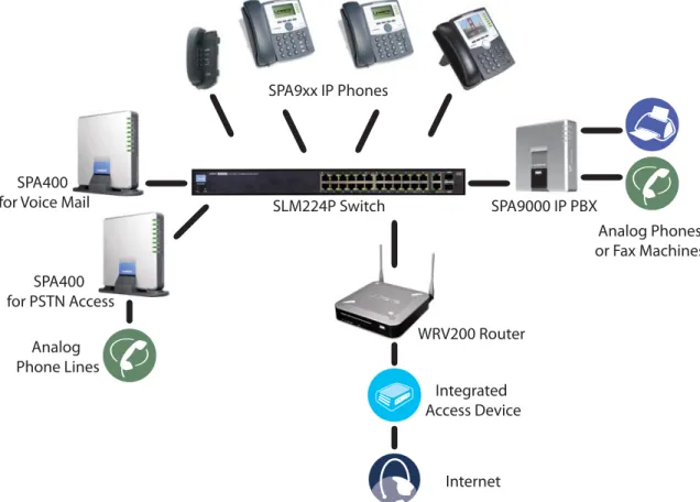
At minimum, the LVS includes a SPA9000 IP PBX and one or more SPA900 series IP phones. These devices are connected through a switch to a local area network. With an Internet connection, the LVS can subscribe to ITSP services to take advantage of low calling rates. With the optional SPA400, the LVS can connect to the Public Switched Telephone Network (PSTN) to support legacy phone lines. Figure 1-1 illustrates the LVS Solution in a typical deployment.
Figure 1-1 The Linksys Voice System (LVS) with the SPA9000 and SPA400
SPA9xx IP Phones
SLM224P Switch SPA9000 IP PBX
WRV200 Router
Internet Integrated Access Device Analog
Phone Lines SPA400 for Voice Mail
SPA400 for PSTN Access
Analog Phones or Fax Machines
Introduction to the Linksys Voice System
SPA9000 IP PBX
The SPA9000 is an IP PBX that supports up to 16 phones. It also has a built-in Analog Telephone Adapter (ATA) with two FXS ports for analog telephones, fax devices, or an external music source for the music on-hold service. Devices connected to the FXS ports are not included in the licence's device count.
The SPA9000 has four line interfaces, which can be configured in any combination for ITSP service, ISDN access, SPA400 PSTN access, or SPA400 voice mail service. A different ITSP account can be configured on each line interface. If a service provider supplies a group of sequential direct inward dial (DID) phone numbers (such as 408-555-0100 through 555-0145) the SPA9000 can support all of the assigned numbers on a single line interface.
The SPA9000 includes an Auto Attendant service that plays pre-recorded voice messages to offer the caller a menu of choices and to direct the call. When the Auto-Attendant is enabled, it parses and operates on user input (key presses that produce DTMF tones) following the rules specified in the Auto Attendant script on the SPA9000.
SPA400 SIP-PSTN Gateway and Voicemail Server
The SPA400 provides a SIP-PSTN gateway for voice connectivity between the PSTN and the local client stations that are connected to the SPA9000. It also includes an integrated voice mail application that supports up to 32 voice mail accounts with customized greetings, providing LVS users the ability to receive and playback voice mail messages.
Each SPA400 occupies one of the four line interfaces on the SPA9000. The SPA400 has four ports for that can be connected to PSTN or ISDN lines.
SPA900 Series IP Phones and Accessories
Linksys provides a variety of IP phones to meet the needs of small businesses. Table 1-1 provides a comparison of the available models.
NOTE: This guide explains how to configure the SPA9000 and the SPA400 to support the calling features on the phones. For more information about the phones, see the Linksys Phone
Administration Guide and the Linksys SPA9x2 Phone User Guide.
Table 1-1 Linksys SP900 Series IP Phones and Accessories
Product RJ-45 Voice Lines Additional Features/
Notes
SPA922* 2 1 One-line IP phone with
Power over Ethernet (PoE) support
Deployment Scenarios
* NOTE: SPA922, SPA942, SPA962 do not include an external power adapter as they support Power over Ethernet (802.3af ). If the phones are connected to a non-POE switch, the PA100 power adapter is required.
Deployment Scenarios
The LVS can meet the calling needs of many small businesses. Various deployment scenarios are possible. This section includes the following examples:
• ”Deploying the LVS with PSTN Access and Local Voice Mail,” on page 16 • ”Deploying the LVS with ITSP Service Only,” on page 17
• ”Deploying the LVS with ITSP Service, PSTN Access and Local Voice Mail,” on page 18
SPA932 — — Attendant console (sidecar)
for SPA962 with 32 buttons and LEDs for monitoring and call transfer
SPA942* 2 4 Four-line IP phone with
Power over Ethernet (PoE) support
SPA962* 2 6 Six-line IP Phone with
high-resolution color display and Power over Ethernet (PoE) support
POES5 1 N/A Provides an 802.3af PoE
port for connection back to a PoE switch for SPA9000, SPA400 and SPA9x1 phones
WBP54G 1 N/A Converts your IP phone
into a wireless device, so it can connect to your wireless network without an Ethernet cable
Product RJ-45 Voice Lines Additional Features/
Deployment Scenarios
• ”ITSP Service, PSTN and ISDN Access and Local Voice Mail,” on page 19
Deploying the LVS with PSTN Access and Local Voice Mail
In this scenario, the customer requires a robust phone system but is not using VoIP services. The LVS is deployed with a SPA9000 IP PBX, one SPA400 for PSTN access with four FXO ports, and another SPA400 for local voice mail service. Optionally, analog phones or fax machines (not illustrated) can be connected to the two phone ports on the SPA9000.
SPA9xx IP Phones
SLM224P Switch SPA9000 IP PBX
Analog Phone Lines SPA400
for Voice Mail
SPA400 for PSTN Access
Deployment Scenarios
Deploying the LVS with ITSP Service Only
In this scenario, a customer has no legacy telephone numbers and does not require local voice mail (either needs no voice mail at all or has voice mail hosted by the ITSP). The LVS is deployed with the SPA9000 IP PBX, VoIP service, and four SPA9x2 series phones. Four phones are
connected at this time, but the LVS can be expanded to include 16 SPA9xx IP phones.
Optionally, analog phones or fax machines (not illustrated) can be connected to the two phone ports on the SPA9000.
SPA9xx IP Phones
SLM224P Switch
SPA9000 IP PBX
WRV200 Router
Internet Integrated Access Device
Deployment Scenarios
Deploying the LVS with ITSP Service, PSTN Access and Local Voice Mail
In this scenario, the customer wants to use ITSP service for reduced long distance fees but needs to support legacy local telephone numbers (for example, to receive calls over the original legacy telephone number, or to route local telephone calls). This customer also prefers local voice mail service. The LVS is deployed with the SPA9000 IP PBX, VoIP service, one SPA400 unit for voice mail service, another SPA400 units for PSTN access with four FXO ports, and up to 16 SPA900 series phones. Optionally, analog phones or fax machines (not illustrated) can be connected to the two phone ports on the SPA9000.SPA9xx IP Phones
SLM224P Switch SPA9000 IP PBX
WRV200 Router
Internet Integrated Access Device Analog
Phone Lines SPA400 for Voice Mail
SPA400 for PSTN Access
Deployment Scenarios
ITSP Service, PSTN and ISDN Access and Local Voice Mail
In this scenario, the customer takes full advantage of the LVS solution, with the SPA9000 IP PBX, VoIP service, one SPA400 unit for voice mail service, another SPA400 for PSTN access with four FXO ports, one ISDN Gateway for ISDN BRI access with four BRI ports, and up to 16 SPA9xx IP phones. Optionally, analog phones or fax machines (not illustrated) can be connected to the two phone ports on the SPA9000.
SPA9xx IP Phones
SLM224P Switch SPA9000 IP PBX
WRV200 Router
Internet Integrated Access Device Analog
Phone Lines SPA400 for Voice Mail
SPA400 for PSTN Access
Mediatrix® 4402 BRI Gateway ISDN
Initial Installation, and Configuration
Initial Installation, and Configuration
Linksys strongly recommends that you use the Linksys Voice System Installation and
Configuration Guide to design your system, to prepare the site, to connect and configure your equipment, and to set up the essential calling features. By following the instructions in the installation guide, you can get your system running in less time and with the settings that help to ensure strong performance.
After you complete the procedures in the installation guide, the users can make and receive calls. When the optional SPA400 is installed, the users also can record and retrieve voice mail messages. The SPA9000 has a fully functional Auto Attendant to greet callers, and a default dial plan that is suitable for most dialing scenarios. You can use this administration guide to refine the settings, to configure advanced features, and to manage the system.
NOTE: Because the Linksys Voice System Installation and Configuration Guide provides all of the procedures that you need for initial installation and configuration, those instructions are not duplicated in this administration guide.
2
Upgrading Firmware for the SPA9000Basic Administration of the SPA9000
This chapter introduces you to basic administrative tasks using the SPA9000 administration web server and the Interactive Voice Response Unit.For Installation and Configuration of LVS in the most common deployment scenarios, refer to the Linksys Voice System Installation and Configuration Guide, which is available at Linksys.com. See the following topics:
• ”Upgrading Firmware for the SPA9000,” on page 21
• ”Connecting to the SPA9000 Administration Web Server,” on page 24 • ”Saving or Discarding Changes SPA9000,” on page 24
• ”Access Levels,” on page 25
• ”Setting Passwords for User and Administrator Accounts,” on page 25 • ”Configuring Basic Settings,” on page 26
• ”Viewing Information about the SPA9000,” on page 33 • ”Viewing Information about Client Stations,” on page 33 • ”Using the Interactive Voice Response Unit,” on page 33
Upgrading Firmware for the SPA9000
As needed, you can download new firmware from Linksys.com and then install the firmware on the SPA9000.
1. Download the firmware from Linksys.com by completing the following steps: a. Start a web browser and enter the following address: www.linksys.com. b. On the menu at the top of the page, choose Support > Technical Support. c. Click Choose a Product.
d. From the Voice over IP (VoIP) drop-down list, choose IP PBX.
e. On the Choose the Device IP PBX page, choose SPA9000 from the drop-down list on the left side of the page.
Upgrading Firmware for the SPA9000
f. On the Technical Support page, click the link in the Downloads section.
g. On the SPA9000 Downloads page, choose the version from the Please select a version
drop-down list.
h. In the Firmware section, click the link for the version that you want to install, and then save the file on the administration computer.
2. Extract the Zip file, and then run the executable file to upgrade the firmware. When the
Firmware UpgradeWarning window appears, click Continue.
Upgrading Firmware for the SPA9000
4. In the Confirm Upgrade window, verify that the correct device information and product number appear. Then click Upgrade.
5. When the confirmation message appears, click OK.
Connecting to the SPA9000 Administration Web Server
a. Connect to the SPA9000 administration web server, and choose Admin access with Advanced settings. (See ”Connecting to the SPA9000 Administration Web Server,” on page 24).
b. Review the Router > Status page. The Software Version field should show the firmware version that you installed.
NOTE: You may need to refresh your browser to display the updated page reflecting the new version number.
Connecting to the SPA9000 Administration Web Server
To connect to the SPA9000 administration web server, perform the following steps. 1. Start Internet Explorer on any computer that is connected to the same network as the
SPA9000.
NOTE: You should have previously connected and configured the SPA9000 as described in the LVS Installation Guide.
2. Enter the IP address of the SPA9000.
NOTE: You can find the IP address of the SPA9000 by connecting an analog telephone to the Phone 1 or Phone 2 port on the SPA9000. Then lift the receiver of the phone and press **** on the keypad to access the IVR menu. Press 110# to hear the IP address.
3. To view administrative features, click Admin Login and then click Advanced.
NOTE: By default, no password is required. For more information, see ”Setting Passwords for User and Administrator Accounts,” on page 25.
ALTERNATIVELY: After starting Internet Explorer, enter: <SPA9000_ipaddress>/admin/ advanced
Saving or Discarding Changes SPA9000
Changes can be saved or discarded at any time.
• Changes are submitted only when you click the Submit All Changes button at the bottom of a page. When changes are saved, the SPA9000 may reboot, depending on the type of changes.
• To discard unsubmitted changes, click the Undo All Changes button at the bottom of the page.
• Unsubmitted changes are retained when you move among the pages within the Voice module or the Router module. This feature allows you to make changes on various pages within a module before clicking Submit All Changes.
• Unsubmitted changes are discarded when you switch between the Router and Voice tabs, between the User and Administrator accounts, or between the Basic and Advanced views.
Access Levels
Access Levels
You can use the SPA9000 administration web server to configure and manage your system. Three levels of access are available:
• User Level: The User account only has the privilege to access part of the web profile parameters.
• Administrator Level: The Administrator account has the privilege to modify all the web profile parameters and can also modify the passwords of both Administrator and User account.
• Advanced: Administrators and Users can view advanced features by clicking the Advanced link in the top right corner or lower left corner of the menu bar.
By default, no passwords are assigned for either the Administrator account or the User account. If the password has been set for the Administrator account, the browser prompts for
authentication.
You can switch from User access to Administrator access by clicking the Admin Login link. Likewise, you can switch from Administrator access to User access by clicking the User Login link. If a password is set, you will be prompted to enter the password after you click the link.
Setting Passwords for User and Administrator Accounts
The Administrator account name for the SPA9000 is admin (with a lower-case a) and the User account name is user. These account names cannot be changed.
Note The system prompts for an Administrator account password only if a password has been set. By default, there is no password. You should set a password to protect your SPA9000 from unauthorized access.
TIP: Before you make changes, it is recommended that you save a copy of your current working configuration:
1. In Internet Explorer, connect to the administration web server.
2. From the menu, choose File > Save As.
3. Save the configuration as Web Page Complete. You can use the saved file to review the saved settings in all pages of the administrative GUI. NOTE: To save a Telephone Configuration, first enter the IP address for the configuration, and then follow the above procedure.
Configuring Basic Settings
1. Connect to the SPA9000 administration web server, and choose Admin access with Advanced settings. (See ”Connecting to the SPA9000 Administration Web Server,” on page 24.)
2. Click Voice tab > System.
3. In the System Configuration section, enter the Admin Password and the User Password, as needed. Up to 39 characters are allowed for the passwords.
4. Click Submit All Changes.
Configuring Basic Settings
This section provides information about the following tasks:
• ”Setting Up the WAN Connection for the SPA9000,” on page 26 • ”Setting the Date and Time,” on page 27
• ”Configuring Daylight Saving Time,” on page 27 • ”LAN and Application Guidelines,” on page 28
• ”Configuring Multicast Addressing and Group Paging,” on page 29 • ”Collecting System Logs and Debug Information,” on page 31
Setting Up the WAN Connection for the SPA9000
The SPA9000 becomes a DHCP client of any server on the network. The recommended setting is to use a static IP address. This configuration provides ease of installation and prevents connectivity issues that would occur if the IP address of the SPA9000 changed.
1. Connect to the SPA9000 administration web server, and choose Admin access with Advanced settings. (See ”Connecting to the SPA9000 Administration Web Server,” on page 24.)
2. Click Router tab > Wan Setup.
3. From the Connection Type drop-down list, choose Static IP.
4. In the Static IP Settings area, enter the Static IP of the SPA9000, as well as the NetMask and
Gateway for your network.
5. In the Optional Settings area, enter the Primary DNS for your network.
NOTE: It is recommended to set an IP address that is outside the address range assigned by the DHCP server. For example, if the DHCP server assigns IP addresses in the range from 192.168.1.50 to 192.168.1.254, you should select a static IP address between 192.168.1.2 and 192.168.1.49.
Configuring Basic Settings
Setting the Date and Time
The date and time appear on the phone display and are used to activate the daytime and nighttime Auto Attendant settings. Normally the date and time are set by the network, which has a connection to an NTP server. If needed, you can identify the NTP server on the Voice > Wan Setup page, Optional Settings section.
Note Do not use the date/time settings on the Voice > Regional page to set your system time.
1. Connect to the SPA9000 administration web server, and choose Admin access with Advanced settings. (See ”Connecting to the SPA9000 Administration Web Server,” on page 24).
2. Click Router tab > Wan Setup.
3. Scroll down to the Optional settings section.
4. Enter the fully qualified domain name of the NTP server that you want to use, such as time.nist.gov.
5. Click Submit All Changes. 6. Click Voice tab > Regional.
7. Scroll down to the Miscellaneous section.
8. From the Time Zone drop-down list, choose your local time zone. 9. Click Submit All Changes.
10.
Configuring Daylight Saving Time
You can enter a daylight saving time rule to ensure that the time is adjusted appropriately for your region.
Syntax and Examples
SYNTAX:start = <start-time>; end=<end-time>; save = <save-time> EXAMPLE:start=3/9/7;end=11/2/7;save=1
In this example, Daylight Saving Time begins March 9, 2007, and ends Nov. 2, 2007. One hour is added to the time of day during this period.
• The <start-time> and <end-time> values specify the start and end dates and times of daylight saving time. Each value is in the following format: <month> /<day> /
Configuring Basic Settings
• The <save-time> value is the number of hours, minutes, and/or seconds to add to the current time during daylight saving time. The <save-time> value can be preceded by a negative (-) sign if subtraction is desired instead of addition. The <save-time> value is in this format: [/[+|-]HH:[mm[:ss]]]
• The <month> value equals any value in the range 1-12 (January-December). • The <day> value equals [+|-] any value in the range 1-31. If <day> is 1, it means the
<weekday> on or before the end of the month (in other words the last occurrence of <weekday> in that month).
• The <weekday> value equals any value in the range 1-7 (Monday-Sunday). It can also equal 0. If the <weekday> value is 0, this means that the date to start or end daylight saving is exactly the date given. In that case, the <day> value must not be negative. If the <weekday> value is not 0 and the <day> value is positive, then daylight saving starts or ends on the <weekday> value on or after the date given. If the <weekday> value is not 0 and the <day> value is negative, then daylight saving starts or ends on the <weekday> value on or before the date given.
• The abbreviation HH stands for hours (0-23). • The abbreviation mm stands for minutes (0-59). • The abbreviation ss stands for seconds (0-59). Entering the Daylight Saving Time Rule
1. Connect to the SPA9000 administration web server, and choose Admin access with Advanced settings. (See ”Connecting to the SPA9000 Administration Web Server,” on page 24).
2. Click Voice tab > Regional.
3. Scroll down to the Miscellaneous section.
4. Enter the rule in the Daylight Saving Time Rule field. 5. Click Submit All Changes.
SPA9000 Ethernet Port
The SPA9000 Ethernet port is used to connect an administrative computer. Typically, this port is used only during initial installation and configuration. With WAN access enabled by default, you can manage your SPA9000 from any computer that is connected to the same subnetwork as the SPA9000. The default IP address for this port is 192.168.0.1.
LAN and Application Guidelines
Although the SPA9000 can provide router and Application services, it does not have sufficient power to provide both phone and routing/application services in a highly utilized
environment. For this reason, Linksys recommends that the SPA9000 not be used as a router at any time. Instead, use the SPA9000 as an appliance by connecting its INTERNET port to a network switch and leaving the ETHERNET port disconnected.
Configuring Basic Settings
Configuring Multicast Addressing and Group Paging
For initialization and system updates, the SPA9000 communicates with all the client stations at once by using IP multicast. This method also is used in the group paging application. For this reason, the SPA9000 and the SPA9xx IP phones must reside on a network where multicasting is allowed. Default addresses are provided, but you can change these addresses as needed.
Note Make sure that the SPA9000 and the SPA900 Series phones use the same multicast address and port number. Also make sure that you enable spanning tree and port fast on your LAN switch, as described in the LVS Installation and Configuration Guide.
Setting the Multicast Address
For administration purposes, the SPA9000 can send the following reboot, restart, page, and ring messages to the group:
• Graceful reboot • Immediate reboot • Graceful restart • Immediate restart • Group page start • Group page end • Get ringing calls
1. Connect to the SPA9000 administration web server, and choose Admin access with Advanced settings. (See ”Connecting to the SPA9000 Administration Web Server,” on page 24).
2. Click Voice tab > SIP.
3. Scroll down to the PBX Parameters section.
Configuring Basic Settings
NOTE: The default value is 224.168.168.168:6061. 5. Click Submit All Changes.
6. Enter the same multicast address in the phone configurations: a. Click the PBX Status link to view a list of all phones.
b. Find the phone that you want to configure, and then click the hyperlink in the IP Address
column. The Telephone Configuration page appears in a separate browser window. c. Click the SIP tab.
d. Scroll down to the Linksys Key System Parameters section. e. Enter the IP address in the Multicast Address field.
f. Click Submit All Changes.
g. Click the Back button on the Internet Explorer toolbar to return to the list of phones. h. Repeat these steps for each phone.
Setting the Group Page Address
In the group paging application, the originator sends RTP packets to an IP multicast address at which all the other client stations are listening. This address is chosen by the SPA9000 and is configured on the Voice > SIP page, PBX Parameters section, Group Page Address field.
The originator starts the group page by choosing PageGroup from the Corporate Directory on the phone, or by using a speed dial or personal directory entry. All client stations are alerted at once. If the client station is on a call when a group page starts, the call is automatically placed on hold. The speaker on each paged station is turned on automatically unless the handset or headset is being used. Group page is one-way only. The paged client stations can only listen to the call from the originator.
1. Connect to the SPA9000 administration web server, and choose Admin access with Advanced settings. (See ”Connecting to the SPA9000 Administration Web Server,” on page 24).
2. Click Voice tab > SIP.
Configuring Basic Settings
4. Enter the correct multicast address in the Group Page Address field.
NOTE: The default value is 224.168.168.168:34567. 5. Click Submit All Changes.
Collecting System Logs and Debug Information
If you are working with an ITSP that needs more information to configure interoperability, you can collect system logs and debug information for the SPA9000. You can send these logs to the ITSP for their use.
Requirements:
• You need a PC that is on the same subnetwork as the SPA9000, to capture the log files. This PC needs to be running a syslog daemon. Enter the IP address of this PC on the
Voice > System page, in the Syslog Server and Debug Server fields.
• If you are interested in working with these logs yourself, you will need to use an application that reads syslogs. Linksys partners can download a syslog server tool (slogsrv.exe) from the Linksys Partner Connection. (VARs, see Product Utilities > Linksys Voice System > SPA Utilities > Syslog Server for SPA Devices. SPs, see Technical Tools > SPA Utilities > Syslog Server for SPA Devices.)
Note As a best practice, enable logging only when needed, and disable logging when you finish the investigation. Logging information can impact system performance.
1. Connect to the SPA9000 administration web server, and choose Admin access with Advanced settings. (See ”Connecting to the SPA9000 Administration Web Server,” on page 24).
Configuring Basic Settings
3. In the Miscellaneous Settings section, enter the following settings:
• Syslog Server: Enter the server IP address and port to collect basic information about system activity (no SIP messages).
• Debug Server: Enter the server IP address and port to collect information about SIP messages.
NOTE: SIP logging is not enabled until you complete this procedure by enabling system logging on the line interface.
i. Debug Level: Choose 3 to enable debugging.
4. Click Voice tab > Line N, where N represents the line interface number of the line that you are investigating.
5. Scroll down to the SIP Settings section, and then choose a SIP Debug Option, based on the level of SIP information that you want to collect.
NOTE: Typically, your ITSP support personnel will tell you what type of information they need in the logs. The drop-down list includes three categories of options: none,1- line, and
full.
• none: Disables SIP logging
• 1-line: Identifies the SIP message type but does not include the message body Options within this category allow you to choose to exclude OPT, NTFY, and REG information to reduce the length of the logs.
• full: Includes the SIP message body
Options within this category allow you to choose to exclude OPT, NTFY, and REG information to reduce the length of the logs.
EXAMPLES:
• If you are troubleshooting a problem with line registration. Select full. • If you are troubleshooting a call problem. Select full excl. OPT|NTFY|REG.
6. Click Submit All Changes. The information is stored on the specified server and port, with a file name in the following format: syslog.port.log.
7. IMPORTANT: When you finish collecting the information, disable the logging: a. Click Voice tab > Line. Change SIP Debug Option to none.
b. Click Voice tab > System. In the Miscellaneous Settings section, change Debug Level to0.
Viewing Information about the SPA9000
Viewing Information about the SPA9000
The Router Status page provides information about software version, hardware version, MAC address, WAN connection type, IP address, and the packets that have been sent and received.
SPA9000 Router > Status
Viewing Information about Client Stations
The PBX Status page provides information about the client stations (IP phones), with hyperlinks to station configuration pages.
1. Connect to the SPA9000 administration web server, and choose Admin access with Advanced settings. (See ”Connecting to the SPA9000 Administration Web Server,” on page 24).
2. To view the status information for the client stations, click the PBX Status link in the top right corner or lower left corner of the page. The list of client stations appears.
SPA9000 > PBX Status
3. To view the Telephone Configuration page for any station, click the hyperlink in the IP Address
column. For information about the telephone configurations, see the Linksys Phone Administration Guide.
Using the Interactive Voice Response Unit
In addition to the administration web server, the SPA9000 is equipped with an Interactive Voice Response unit (IVR) that allows you to perform certain administrative tasks by using an analog phone that is connected to the SPA9000.
Using the Interactive Voice Response Unit
• ”Using the IVR Menu,” on page 34
• ”Entering a Password through the IVR,” on page 37
Using the IVR Menu
To use the IVR menu, complete the following steps.
1. Connect an analog telephone to the Phone 1 or Phone 2 port of the SPA9000. 2. Press **** (quicklypress the star key four times).
3. Wait until you hear “Linksys configuration menu.” 4. Refer to Table 2-1 to identify the option required. 5. Enter the required option followed by the # (pound) key.
NOTE:
• To enter a period, use the star key (*).
• When entering a value, such as an IP address, to exit without entering any changes, press the * (star) key twice within half a second. Otherwise, the * is treated as a decimal point.
• After entering a value, such as an IP address, press the # (pound) key to indicate you have finished your selection.
• To save a new setting, press 1. To review a new setting, press 2. To re-enter a setting, press 3. To cancel your entry and return to the main menu, press * (star).
For example, to enter the IP address 191.168.1.105 by keypad, press the following keys: 191*168*1*105. Press the # (pound) key to indicate that you have finished entering the IP address. Then press 1 to save the IP address, or press the * (star) key to cancel your entry and return to the main menu.
• If the menu is inactive for more than one minute, the SPA9000 times out. You need to re-enter the menu by pressing ****.
6. To exit the menu, hang up the telephone.
The settings that you have saved take effect after you hang up the telephone. The SPA9000 may reboot at this time.
Using the Interactive Voice Response Unit
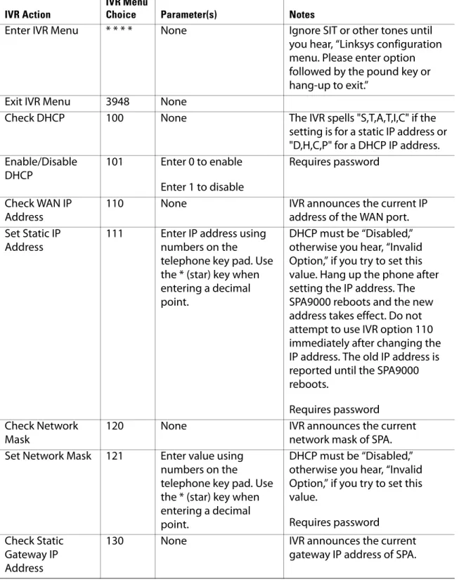
Table 2-1 IVR Options
IVR Action
IVR Menu
Choice Parameter(s) Notes
Enter IVR Menu * * * * None Ignore SIT or other tones until you hear, “Linksys configuration menu. Please enter option followed by the pound key or hang-up to exit.”
Exit IVR Menu 3948 None
Check DHCP 100 None The IVR spells "S,T,A,T,I,C" if the setting is for a static IP address or "D,H,C,P" for a DHCP IP address. Enable/Disable
DHCP
101 Enter 0 to enable Enter 1 to disable
Requires password
Check WAN IP Address
110 None IVR announces the current IP
address of the WAN port. Set Static IP
Address
111 Enter IP address using numbers on the
telephone key pad. Use the * (star) key when entering a decimal point.
DHCP must be “Disabled,” otherwise you hear, “Invalid Option,” if you try to set this value. Hang up the phone after setting the IP address. The SPA9000 reboots and the new address takes effect. Do not attempt to use IVR option 110 immediately after changing the IP address. The old IP address is reported until the SPA9000 reboots.
Requires password Check Network
Mask
120 None IVR announces the current
network mask of SPA. Set Network Mask 121 Enter value using
numbers on the
telephone key pad. Use the * (star) key when entering a decimal point.
DHCP must be “Disabled,” otherwise you hear, “Invalid Option,” if you try to set this value.
Requires password Check Static
Gateway IP Address
130 None IVR announces the current
Using the Interactive Voice Response Unit
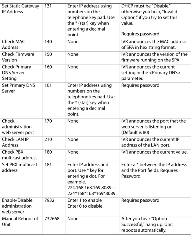
Set Static Gateway IP Address
131 Enter IP address using numbers on the
telephone key pad. Use the * (star) key when entering a decimal point.
DHCP must be “Disable,” otherwise you hear, “Invalid Option,” if you try to set this value.
Requires password Check MAC
Address
140 None IVR announces the MAC address
of SPA in hex string format. Check Firmware
Version
150 None IVR announces the version of the
firmware running on the SPA. Check Primary
DNS Server Setting
160 None IVR announces the current
setting in the <Primary DNS> parameter.
Set Primary DNS Server
161 Enter IP address using numbers on the
telephone key pad. Use the * (star) key when entering a decimal point.
Requires password
Check
administration web server port
170 None IVR announces the port that the
web server is listening on. (Default is 80)
Check LAN IP Address
210 None IVR announces the current IP
address of the LAN port. Check PBX
multicast address
180 None IVR announces the current value.
Set PBX multicast address
181 Enter IP address and port. Use * key for entering a dot. For example,
224.168.168.169:8089 is 224*168*168*169*8089.
Enter a * between the IP address and the Port fields. Requires Password
Enable/Disable administration web server
7932 Enter 1 to enable Enter 0 to disable
Requires password
Manual Reboot of Unit
732668 None After you hear “Option
Successful,” hang up. Unit reboots automatically.
Using the Interactive Voice Response Unit
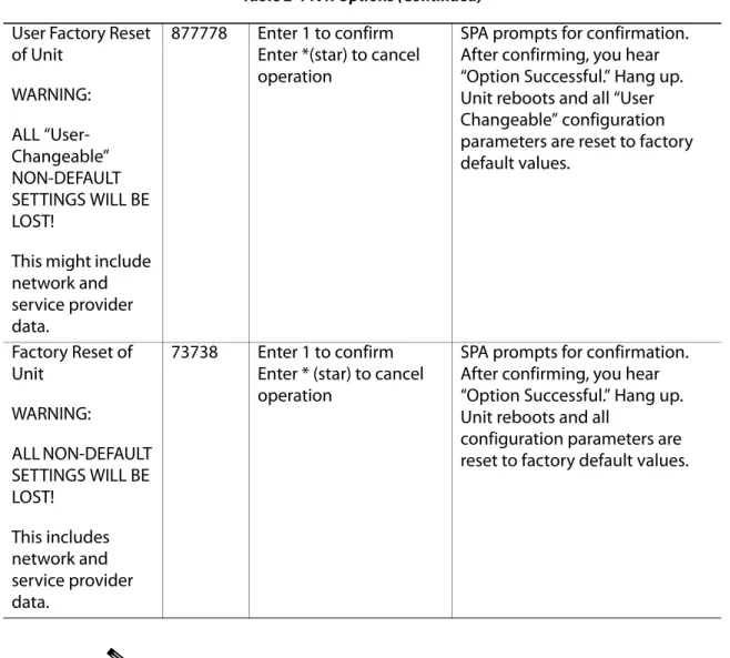
Note The items marked with “Requires Password” only require a password if the Administrator password is set.
Entering a Password through the IVR
To input the password using the phone keypad, the following translation conventions apply:
– To input: A, B, C, a, b, c—press “2’ – To input: D, E, F, d, e, f—press “3’ – To input: G, H, I, g, h, i—press “4’ – To input: J, K, L, j, k, l— press “5’ – To input: M, N, O, m, n, o—press “6’ – To input: P, Q, R, S, p, q, r, s—press “7’ User Factory Reset
of Unit WARNING: ALL “User-Changeable” NON-DEFAULT SETTINGS WILL BE LOST!
This might include network and service provider data.
877778 Enter 1 to confirm Enter *(star) to cancel operation
SPA prompts for confirmation. After confirming, you hear “Option Successful.” Hang up. Unit reboots and all “User Changeable” configuration parameters are reset to factory default values.
Factory Reset of Unit
WARNING:
ALL NON-DEFAULT SETTINGS WILL BE LOST!
This includes network and service provider data.
73738 Enter 1 to confirm Enter * (star) to cancel operation
SPA prompts for confirmation. After confirming, you hear “Option Successful.” Hang up. Unit reboots and all
configuration parameters are reset to factory default values.
Using the Interactive Voice Response Unit
– To input: T, U, V, t, u, v—press “8’ – To input: W, X, Y, Z, w, x, y, z—press “9’
– To input all other characters in the Administrator account password, press “0’
Note This translation convention only applies to the password input. For example, to input password test#@1234 by phone keypad, you need to press the following sequence of digits: 8378001234.
1. After entering a value, press the # (pound) key to indicate end of input. • To save value, press 1.
• To review the value, press 2. • To re-enter the value, press 3.
• To cancel the value entry and return to the main configuration menu, press
*
’ (star). NOTES:– The final # key is not included in the password value.
– Saved settings take effect when the telephone is hung-up, and if necessary, the SPA9000 automatically reboots.
2. After one minute of inactivity, the unit times out. The user needs to re-enter the configuration menu from the beginning by pressing * * * *.
3
About LVS and SIPConfiguring the SPA9000 for ITSP
Interoperability
This chapter provides configuration details for the purpose of helping you to ensure that your infrastructure properly supports the LVS.
• ”About LVS and SIP,” on page 39
• ”Network Address Translation (NAT) and Voice over IP (VoIP),” on page 40 • ”Firewalls and SIP,” on page 43
• ”Configuring SIP Timer Values,” on page 44
About LVS and SIP
The LVS is implemented using open standards, such as Session Initiation Protocol (SIP), to help ensure interoperation with all ITSPs that support SIP. This section provides information about the SIP requests and the settings that you may need to adjust on your network or your SPA9000 to help ensure interoperability.
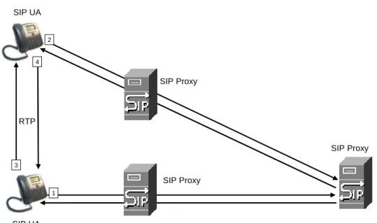
The VoIP telephone service is coordinated by SIP requests and responses, whether the calls are internal or external. Figure 3-1 illustrates the SIP requests and responses between client stations in the LVS. The SPA9000 acts as a SIP proxy and establishes a session. After the session is established, Real Time Protocol (RTP) traffic flows directly between the two client stations.
Figure 3-1 SIP Requests and Responses for Internal Calls
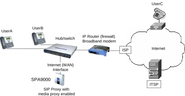
Likewise, SIP requests and responses are exchanged to support outbound and inbound calls that are handled through the ITSP service. In Figure 3-2, UserA and UserB are client stations that are registered to the SPA9000. When UserA calls UserC, the SPA9000 directs the request to the SIP proxy at the ITSP, which is then responsible for routing the request to UserC. After the
SIP UA SIP UA
SIP Proxy SIP Proxy
RTP
1 2
3 4
Network Address Translation (NAT) and Voice over IP (VoIP)
Figure 3-2 SPA9000 as a SIP Proxy for Internet Calls
Network Address Translation (NAT) and Voice over IP (VoIP)
NAT is a function that allows multiple devices to share the same public, routable, IP address to establish connections over the Internet. NAT is present in many broadband access devices to translate public and private IP addresses. To enable VoIP to co-exist with NAT, some form of NAT traversal is required.
Some ITSPs provide NAT traversal, but some do not. If your ITSP does not provide NAT traversal, you have several options.
• ”NAT Mapping with SIP-ALG Router,” on page 40
• ”NAT Mapping with Session Border Controller,” on page 41 • ”Configuring NAT Mapping with a Static IP Address,” on page 41 • ”Configuring NAT Mapping with STUN,” on page 42
NAT Mapping with SIP-ALG Router
You can achieve NAT mapping by using a router that has a SIP ALG (Application Layer Gateway). The Linksys WRV200 router is recommended for this purpose, although any router with a SIP-ALG can be used. By using a SIP-SIP-ALG router, you have more choices in selecting an ITSP.
SIP Proxy with media proxy enabled
Internet IP Router (firewall)
Broadband modem Hub/switch
SPA9000
UserA UserB
UserC
Internet (WAN) Interface
ITSP ISP
Network Address Translation (NAT) and Voice over IP (VoIP)
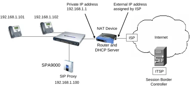
NAT Mapping with Session Border Controller
It is strongly recommended that you choose an ITSP that supports NAT mapping through a Session Border Controller (see Figure 3-3). With NAT mapping provided by the ITSP, you have more choices in selecting a router.
Figure 3-3 NAT Support with Session Border Controller Provided by ITSP
Configuring NAT Mapping with a Static IP Address
Configuring NAT mapping in the SPA9000 is recommended only if the ITSP network does not provide a Session Border Controller functionality. In this case, and if the external (public) IP address is static, then it is recommended to perform a static (permanent) mapping on SPA9000. This setting is also recommended if NAT mechanism used in the router is symmetric.
Note The LAN switch needs to be configured to enable Spanning Tree Protocol and Port Fast on the ports to which the SPA9000 and the SPA9xx phones are connected.
1. Connect to the SPA9000 administration web server, and choose Admin access with Advanced settings. (See ”Connecting to the SPA9000 Administration Web Server,” on page 24.)
2. Click Voice tab > SIP.
3. Scroll down to the NAT Support Parameters section, and then enter the following settings to support static mapping to your public IP address:
• Handle VIA received, Insert VIA received, Substitute VIA Addr: yes • Handle VIA rport, Insert VIA rport, Send Resp To Src Port: yes • EXT IP: Enter the public IP address for your router.
SIP Proxy
Internet
ITSP NAT Device
SPA9000
192.168.1.102
ISP DHCP
server 192.168.1.101
192.168.1.100 Session Border Controller
Private IP address 192.168.1.1
External IP address assigned by ISP
Router and DHCP Server
Network Address Translation (NAT) and Voice over IP (VoIP)
SPA9000 Voice > SIP: NAT Support Parameters
4. Click Voice tab > Line N, where N is the number of the line interface for the ITSP service that you need to configure.
5. Scroll down to the NAT Settings section. • NAT Mapping Enable: Choose YES.
• NAT Keep Alive Enable: Choose YES (optional).
NOTE: Your ITSP may require the SPA9000 to send NAT keep alive messages to keep the NAT ports open permanently. For more information, see Appendix A, "Advanced Topics in LVS Administration," ”SIP-NAT Interoperation” section on page 135.
6. Click Submit All Changes.
NOTE: You also need to configure the firewall settings on your router to allow SIP traffic. See ”Firewalls and SIP,” on page 43.
Configuring NAT Mapping with STUN
Configuring NAT mapping in the SPA9000 is recommended only if the ITSP network does not provide a Session Border Controller functionality. In this case, and if the external (Public) IP address is assigned dynamically by the network (and the router uses asymmetric NAT mechanism), it is possible to use STUN as a mechanism to discover the NAT mapping in SPA9000. This is considered a practice of last resort and should be used only if the other methods are unavailable.
Note STUN is a viable option only if your router uses asymmetric NAT. See Appendix A, "Advanced Topics in LVS Administration," ”Determining Whether the Router Uses Symmetric or Asymmetric NAT” section on page 136.
1. Connect to the SPA9000 administration web server, and choose Admin access with Advanced settings. (See ”Connecting to the SPA9000 Administration Web Server,” on page 24.)
Firewalls and SIP
3. Scroll down to the NAT Support Parameters section, and then enter the following settings to enable and support the STUN server settings:
• Handle VIA received, Insert VIA received, Substitute VIA Addr: yes • Handle VIA rport, Insert VIA rport, Send Resp To Src Port: yes • STUN Enable: Choose yes.
• STUN Server: Enter the IP address for your STUN server.
4. Click Voice tab > Line N, where N is the number of the line interface for the ITSP service that you need to configure.
5. Scroll down to the NAT Settings section. • NAT Mapping Enable: Choose YES.
• NAT Keep Alive Enable: Choose YES (optional).
NOTE: Your ITSP may require the SPA9000 to send NAT keep alive messages to keep the NAT ports open permanently. For more information, see Appendix A, "Advanced Topics in LVS Administration," ”SIP-NAT Interoperation” section on page 135.
6. Click Submit All Changes.
NOTE: You also need to configure the firewall settings on your router to allow SIP traffic. See ”Firewalls and SIP,” on page 43.
Firewalls and SIP
To enable SIP requests and responses to be exchanged with the SIP proxy at the ITSP, you must ensure that your firewall allows both SIP and RTP unimpeded access to the Internet.
• Make sure that the following ports are not blocked:
– SIP ports—UDP port 5060 through 5063, which are used for the SPA9000 line interfaces
– RTP ports—16384 to 16482
Configuring SIP Timer Values
Configuring SIP Timer Values
The SPA9000 is configured with default timer values that should be adequate in most circumstances. However, you can adjust the SIP timer values as needed to ensure interoperability with your ISTP. For example, if SIP requests are returned with an “invalid certificate” message, you may need to enter a longer SIP T1 retry value.
To view the default settings or to make changes, open the Voice > SIP page, and scroll down to the SIP Timer Values section. For field descriptions, see ”SIP Timer Values (sec) section,” on page 161.
4
Configuring SPA9000 FXS PortsConfiguring Phone Lines and Calling
Routing Behavior
This chapter describes many features that you can configure on the SPA9000 to ensure smooth handling of all inbound and outbound calls, and ease of use.
• ”Configuring SPA9000 FXS Ports,” on page 45
• ”Configuring Line Interfaces on the SPA9000,” on page 46 • ”Configuring Dial Plans,” on page 52
• ”Managing the Line Selection for Outbound Calls,” on page 63 • ”Managing Caller ID Settings for Outgoing Calls,” on page 65 • ”Managing Inbound Calls with the Contact List,” on page 66 • ”Managing Inbound Calls with Hunt Groups,” on page 73
• ”Managing Inbound Calls with Shared Line Appearances,” on page 77
Configuring SPA9000 FXS Ports
The SPA9000 FXS ports can be used to connect analog phones and fax machines to the LVS. A port also can be configured for a Streaming Audio Server for Music On Hold. See Chapter 6, "Configuring Music on Hold."
Note A fax machine can be connected to the Phone port of the SPA9000. Fax support through an ITSP line requires a T.38 fax machine on both ends and the availability of T.38 FAX relay through the ITSP. T.38 support is dependent on fax machine and network / transport resilience. Linksys makes no guarantee with the use of this product regarding fax
transmission services
1. Connect to the SPA9000 administration web server, and choose Admin access with Advanced settings. (See ”Connecting to the SPA9000 Administration Web Server,” on page 24.)
2. Click Voice tab > FXS N, where N is the port number.
3. Scroll down to the Subscriber Information section, and then enter the following settings: • Display Name: Enter an extension number of name for the FXS 1 port, such as
Receptionist Area Fax Machine. You can use this extension number to add the analog phone to the contact list, hunt groups, and shared line appearances.
• User ID: Enter a three- to four-digit extension number that is not is use by other extension.