New Rock Technologies, Inc.
MX Voice-Fax Gateway Series
High Availability Configuration Guide
HX4E MX8A MX60 MX120
Website: http://www.newrocktech.com
Email: [email protected]
1 Overview ... 1-1
1.1 Function Definition ... 1-1 1.2 Server Cluster ... 1-2
2 Configuration ... 2-1
2.1 Configuring Primary-Standby Mode ... 2-1 2.2 Configuring Active-Standby Mode... 2-2 2.3 Configuring Load Balancing Mode ... 2-4
Contents of Figure
Figure 1-1 Server cluster ... 1-2 Figure 2-1 Primary-Standby configuration page ... 2-1 Figure 2-2 DNS server configuration page ... 2-2 Figure 2-3 Active-Standby configuration page ... 2-3 Figure 2-4 Page to disable PSTN failover ... 2-4 Figure 2-5 Load balancing configuration page ... 2-5
MX Voice-Fax Gateway Series High Availability Configuration Guide
New Rock Technologies, Inc. 1-1
1
Overview
1.1 Function Definition
In the deployment of VoIP network, New Rock MX-Series VoIP Gateway (referred as gateway below) supports high availability architecture with Primary-Standby, Active-Standby and Load balancing mode.
Primary-Standby mode
In this mode, a backup SIP proxy server (referred as SIP server) is configured. The gateway will failover to the backup server automatically when the primary server faults. The gateway detects the failure condition of primary server by sending OPTIONS request to it. If the gateway does not receive the response to OPTIONS request, it will failover to the backup server.
After failover to the backup server, the gateway will still send OPTIONS to the primary server all the time. It switches back to the primary server once the response to the OPTIONS request is received.
Active-Standby mode
In this mode, one SIP proxy server (referred as SIP server) functions as the primary server while other SIP servers function as standby servers.
Either of the following conditions could trigger the failover operation of the gateway:
Not receiving response to the OPTIONS message from the current SIP server to which the gateway sends or receives call traffic;
Not receiving response to the REGISTER/INVITE message from the current SIP server to which the gateway send or receives call traffic
The administrator can manually switchover the gateway from the current SIP server to the next available one.
The gateway will redirect call traffic to the designated proxy server in responding to the re-INVITE from the server.
Load balancing mode
In this mode, the clustered SIP servers are all working in active status. Under the coarse grained scheme all endpoints of a gateway are allowed to register on one of the designated servers and under the fine grained scheme the endpoints of a gateway are allowed to register on multiple servers, according to the administrator’s load balancing plan. The following features are supported with load balancing:
The gateway as a whole or endpoints search for the designated sever in the server cluster (a list of servers) using REGISTER/INVITE message in forward circular scheme.
Server failure detetion is supported by gateway sending OPTIONS to each servers, on which the gateway or endpoints are registered on.
the next available servers for the gateway or endpoints and move the calls to them accordingly The gateway will redirect call traffic to the designated proxy server in responding to the re-INVITE from the server.
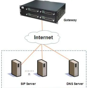
1.2 Server Cluster
The server cluster includes one primary SIP proxy server and one backup SIP proxy server under primary-standby mode, one primary SIP proxy server and up to five standby proxy servers under active-standby mode or six active servers under load balancing mode. The address of the SIP server can be configured manually by the administrator or obtained through DNS SRV record. Topology is shown as Figure 1-1.
MX Voice-Fax Gateway Series High Availability Configuration Guide
New Rock Technologies, Inc. 2-1
2
Configuration
2.1 Configuring Primary-Standby Mode
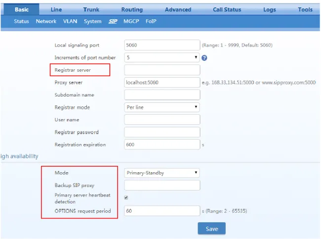
Step1 Click Basic > SIP.Step2 Choose the High availability mode to Primary-Standby.
Step3 Fill primary SIP server IP address or domain name in Registrar server. Step4 Fill backup SIP server IP address in Backup SIP proxy.
Note: This step is required if an IP address is filled in step 3.
When a domain name is filled in step 3, you can also fill in a backup IP address. This allows the device to failover to the backup IP address if the domain name resolution service fails.
Step5 Enable Primary server heartbeat detection, and configure the OPTIONS request period. Step6 Click Save.
Figure 2-1 Primary-Standby configuration page
Step7 Click Basic > Network, make sure DNS server can be obtained automatically or has been specified manually.
2.2 Configuring Active-Standby Mode
Step1 Click Basic > SIP.Step2 Choose the High availability mode to Active-standby.
Step3 Fill primary SIP server IP address or domain name in Registrar server.
Step4 Click Add and fill the IP address for the standby SIP proxy server in Standby SIP server 1. Repeat it for multiple SIP proxy servers.
Note: This step is required if an IP address is filled in step 3.
When a domain name is filled in step 3, you can also fill in a backup IP address in Standby SIP server 1. This allows the device to failover to the backup IP address if the domain name resolution service fails.
Step5 Select to enable or disable OPTIONS Keep-alive.
When OPTIONS Keep-alive is enabled, the following timers need to be configured:
OPTIONS request period: the interval between receiving the response (200) from the SIP server to the previous OPTIONS and sending the next OPTIONS.
OPTIONS request timeout: the period since the sending of the last OPTIONS with no response by the SIP server.
When OPTIONS Keep-alive is disabled, the gateway will failover to the standby SIP server if there is no response to the REGISTER or INVITE.
MX Voice-Fax Gateway Series High Availability Configuration Guide
New Rock Technologies, Inc. 2-3 Figure 2-3 Active-Standby configuration page
The Switchover button provides a means to manually switchover the call traffic from the
current SIP server to the next available SIP server.
Step7 Click Basic > Network, make sure DNS server can be obtained automatically or has been specified manually. See Figure 2-2.
Note: This step is required if a domain name is filled in step 3. Step8 Click Trunk > Advanced, make sure PSTN failover is disabled.
2.3 Configuring Load Balancing Mode
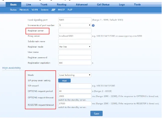
Step1 Click Basic > SIP.Step2 Choose the High availability mode to Load balancing.
Step3 Fill primary SIP server IP address or domain name in Registrar server.
Step4 Click Add and fill the IP address for the standby SIP proxy server in SIP server 1. Repeat it for multiple SIP proxy servers.
Note: This step is required if an IP address is filled in step 3.
When a domain name is filled in step 3, you can also fill in a backup IP address in SIP server 1. This allows the device to failover to the backup IP address if the domain name resolution service fails.
Step5 Configure OPTIONS Settings and REGISTER Settings.
OPTIONS request period: the interval between receiving the response (200) from the SIP server to the previous OPTIONS and sending the next OPTIONS.
OPTIONS request timeout: the period since the sending of the last OPTIONS with no response by the SIP server.
MX Voice-Fax Gateway Series High Availability Configuration Guide
New Rock Technologies, Inc. 2-5
REGISTER request timeout: the period from the sending of the first REGISTER with no response by the previous SIP server to the sending of REGISTER to the next SIP server. Step6 Click Save.
Figure 2-5 Load balancing configuration page
Step7 Click Basic > Network, make sure DNS server can be obtained automatically or has been specified manually. See Figure 2-2.