Latest Power Plant Control System
OVERVIEW: Along with advances in system component technologies, modern state-of-the-art power plant control systems are being developed by incorporating such advanced technologies as extensive digitization of high-speed control circuits, interconnection with other equipment over open interfaces, and a repertory of diverse multiplexed systems. Based on Hitachi Integrated Autonomic Control System (HIACS), Hitachi, Ltd. has developed and deployed a wide range of leading-edge power plant control systems including gas turbine control systems, steam turbine control systems, and generator excitation control systems.
Takashi Kamei Takashi Tomura Yoichi Kato
INTRODUCTION
BESIDES providing a stable source of electrical power, the modern power plant must also be highly efficient, provide good operability, and have minimal adverse effects on the environment. Meeting these demanding requirements calls for plant supervision and operations that are more advanced and at the same time more intuitive and easy to use. And considering the ongoing trend toward liberalization of the energy market, it is also essential to hold down plant construction costs and reduce plant construction schedules.
These were the background factors motivating Hitachi’s development of supervisory and control systems that not only continue to support excellent reliability but also provide good cost-effectiveness while minimizing the workload involved in plant operation and maintenance. Our most recent power plant control systems are based on Hitachi Integrated Autonomic Control System (HIACS), the Company’s comprehensive supervisory and control system that has been extensively deployed and has an excellent reputation for reliability and performance.
This article will describe several of these leading-edge control systems: the gas turbine control system HIACS-MULTI, the steam turbine control system Hitachi Turbine Start up System 2000 (HITASS-2000), and the generator exciter control system VCS-6000.
DISTINGUISHING FEATURES OF THE NEW CONTROL SYSTEMS
Hitachi’s new control systems leverage the latest technologies in HIACS series products.
(1) Digitization of high-speed control circuits Control circuits such as servo valve control circuits requiring high-speed arithmetic operation are
implemented with digital circuits that operate using a PCM (programmable control module). This has not only enabled us to implement the control equipment much more compactly, it also permits personnel to modify and adjust control setting using a maintenance tool, which greatly simplifies these operations. (2) Open interface-based interconnections
Hitachi’s latest control systems can be intercon-nected to other systems and equipment using the serial interface standard RS232, TCP/IP (Transmission Control Protocol/Internet Protocol), and other general-purpose interfaces.
(3) Diverse system repertory
A rich repertory of control system products has been assembled that meets the diverse needs of our customers. The control system panel has also been implemented very compactly so it can be installed in newly constructed plants or easily retrofitted in existing power plants.
GAS TURBINE CONTROL SYSTEM HIACS-MULTI
HIACS-MULTI Series
The HIACS-MULTI series provides a comprehensive gas turbine control system that includes g as turbine control and protection, generator protection, and generator excitation control functions. The system is available in a range of sizes and configurations, thus providing a good repertory of product options tailored to different customers’ needs (see Table 1).
System Configuration
The basic HIACS-MULTI system includes an HMI (human-mac hine interface) that enables plant
supervision and operation from PC (personal computer). A remote HMI can be added in the control network to interconnect multiple HMIs. The HMI now includes a built-in maintenance tool for diagnosing and maintaining CPU (central processing unit) programs, so each HMI has the ability to perform a full range of supervision, operations, and maintenance functions (see Fig. 1).
The servo valve control in HIACS-MULTI is configured using digital circuits, so operators can now monitor control logic online. The servo valves are calibrated by commands from the HMI, thus it is very
user-friendly and intuitive.
Finally, HIACS-MULTI can be interconnected to the DCS (distributed control system) or other equipment over such general-purpose interfaces as RS232 or TCP/IP.
HMI System
The HMI for HIACS-MULTI is a graphical interface that runs on the Windows* operating system. It provides straightforward easy-to-use menu options for plant operation, monitoring, annunciation, display of trends data, servo valve calibration, and other capabilities (see Fig. 2).
Retrofitting the Control System with HIACS-MULTI
Hitachi was recently commissioned to retrofit the PT Pupuk Sriwidjaja (PUSRI) No. 2 gas turbine generator in the Republic of Indonesia with the HIACS-MULTI control system (see Fig. 3). Hitachi supplied this plant some three decades ago in 1973. In this refurbishment, the existing analog gas turbine control system, the generator excitation control system, and the generator protection system were all replaced by the HIACS-MULTI 700 system. This retrofit project was very successful, and the HIACS-MULTI system is now operating smoothly at the PUSRI site.
customer needs.
* Windows is a registered trademark of Microsoft Corp. in the U.S. and other countries.
Fig. 2—Screenshots of the HIACS-MULTI HMI (Online Monitoring Displays for Exhaust Gas Temperatures and Control Logic).
With a range of menu options, the HMI offers an intuitive and easy-to-use user interface.
Fig. 1—Typical System Configuration of the HIACS-MULTI 300 Series.
Supervision, operation, and program maintenance from a single HMI installation. Function Product GT control (simplex) GT control (triple redundant) Generator excitation control Generator protection HIACS-MULTI 100 HIACS-MULTI 200 HIACS-MULTI 300 HIACS-MULTI 500 HIACS-MULTI 700 HIACS-MULTI 700 (S) ✕ ✕ ✔ ✔ ✔ ✕ ✕ ✔ ✕ ✔ ✔ ✔ ✕ ✕ ✕ ✕ ✔ ✔ ✔ ✔ ✕ ✕ ✕ ✔
GT: gas turbine ✔: Provided ✕: Not provided
Remote HMI Central control room Local HMI Control panel
* “2 out of 3” is a voting logic that produces an output by selecting the majority vote from 3 inputs.
CPU-C CPU-B
CPU-A
C-PIO SVD 2 out of 3*
µ∑Network100 (optical fiber cable)
PCM PCM
PCM
SVD: servo valve driver module C-PIO: common process input and output
FEATURES OF NEW STEAM TURBINE CONTROL SYSTEM HITASS-2000
(1) System configuration
The main component elements of the steam turbine control system are the speed/load control unit, the servo valve control unit, the steam turbine automatic start-up control unit, and the turbine protection unit. The system has been enhanced by digital circuits in the PCM for servo valve control, which previously had been implemented by hard-wired circuits.
Fig. 4 is a schematic showing the configuration of
the new steam turbine control system HITASS-2000. (2) Digital servo control
Digital servo control circuit in the PCM enables servo valve calibration easier due to the control parameter tuning capability by control logic software. Maintainability is also enhanced by implementing the current converter, the oscillator, and the rectifier circuit as a single printed circuit board to minimize hardware adjustments.
(3) Steam turbine protection circuit interlock unit The steam turbine protection circuit is fundamentally
Fig. 4—New Steam Turbine Control System Configuration (Dual Controllers).
With far more extensive digitization, a new compact and highly reliable steam turbine control system has been developed that replaces conventional servo valve control circuits and steam turbine protection circuits. (a) Appearance of the control equipment (b) Trend display (c) Operation and monitoring display
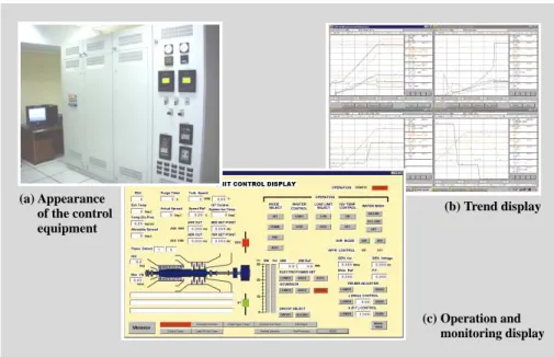
Fig. 3—Screenshots and Appearance of the Control System for the PT PUSRI No. 2 Unit Gas Turbine Power Plant in the Republic of Indonesia.
The control system, that has been in service since Hitachi initially supplied the gas turbine plant back in 1973, was recently replaced by Hitachi’s state-of-the-art digital control system.
CE: control electronics UD: unit driver AO: analog output
Controller A (speed/load control)
Controller B
Same as left
Automatic startup control, common, steam turbine protection
Software
simulator Speed/load controller
Digital servo control PCM
Current converter Digital servo controller Oscillator Valve position detector A Valve position detector B Detector
Trip solenoid valve Servo coil
I/O I/O CE
UD
AI AO
Rectifier 2 out of 3
Trip solenoid valve control circuit AI DI DO Steam turbine protective interlock unit UD Steam turbine protection PCM CE I/O
Turbine automatic startup/ common controller
a digital triple-redundant system to ensure the highest standard of reliability.
The steam turbine protection logic is processed in the PCM, while the I/O (input and output) component (AI: analog input; DI: digital input) for detecting trip factors and the trip signal output component (DO: digital output) are implemented as separate units with triple redundancy. By implementing these functions as separate units, they are completely independent and isolated from other functions. This means that the plant steam turbine protection circuit can be kept running even when the other functions fail.
(4) Maintenance
As a result of more extensive digitization, the internal processing state of the PCM can be monitored using the control system maintenance tool, and this improves the maintainability of the plant. Alarm signals (including steam turbine protection circuits) are interfaced to the computer over a network connection, which enables the number of interface cables to be reduced. In addition, verification and testing of turbine speed and load control functions have been simplified with a software simulator function that includes a built-in model of the steam turbine. Using the simulator, actual servo valves also can be driven for the control function test.
(1) The number of thyristor panels can be increased or deceased to accommodate a full range of generator capacities from small to large (600-MVA class), which simplifies the construction of different scale plant facilities.
(2) Control systems can be implemented as either simplex or as dual systems, so systems can be more closely tailored to users’ needs.
(3) Maintainability, reliability, and performance are upgraded with the development and deployment of VCMI (voltage control module integrated), a single printed circuit control board that integrates voltage controller, logic controller, and GPG (gate pulse generator).
(4) Development and adoption of two new interfaces — GDIO (gate driver and input and output) for the thyristor signal interface and RDIO (remote digital input and output) for the I/O interface — which permits the use of optical signals that are practically immune to noise between VCMIs.
(5) A thyristor switch was adopted in the discharge circuit for cutting off generator field current. This is a cost-saving innovation for it allows us to use general-purpose AC (alternating current) circuit breakers and single-pole DC (direct-current) circuit breakers for the field circuit breakers.
Fig. 5—System Configuration Example of Thyristor Excitation System (Dual Controllers). The new digital excitation system can also be applied to brushless excitation systems.
GP: graphic panel TB: terminal block CBC: craw-bar circuit
PT: potential transformer THY: thyristor DR: discharge resistor EX-TR: exciter transformer THY SW: thyristor switch
Thyristor excitation system
52 System bus PT (A) PT (B) EX-TR THY SW DR CBC AC DC DC GDIO THY#1 THY#n Maximum 6 parallel Optical Optical Optical 41 Data transmission VCMI (B) VCMI (A) Maintenance tool Printer Multiple function TB DI DO
Power supply (A) Power supply (B) RDIO RDIO AI Converter Processor GPG AI GP Processor GPG Converter Generator
ABOUT THE AUTHORS Takashi Kamei
Joined Hitachi, Ltd. in 1993, and now works at the Power Plant Control Systems Engineering Department, the Information & Control Systems Division, the Information and Telecommunication Systems. He is currently engaged in the design of power plant control systems. Mr. Kamei can be reached by e-mail at
Takashi Tomura
Joined Hitachi, Ltd. in 1982, and now works at the Power Plant Control Systems Engineering Department, the Information & Control Systems Division, the Information and Telecommunication Systems. He is currently engaged in the design of power plant control systems. Mr. Tomura can be reached by e-mail at
Yoichi Kato
Joined Hitachi, Ltd. in 1993, and now works at the Power Plant Control Systems Engineering Department, the Information & Control Systems Division, the Information and Telecommunication Systems. He is currently engaged in the design of power plant control systems. Mr. Kato is a member of The Institute of Electrical Engineers of Japan, and can be reached by e-mail at
[email protected]. (6) We also implemented a graphic panel that permits
continuous monitoring of problems that develop and plant operational status. Maintainability is also improved by adopting connectors for all the wiring to the printed circuit boards of controllers.
Fig. 5 shows the schematic of a thyristor excitation system with dual controllers. Note that the VCMI, GDIO, and RDIO can also be applied to brushless excitation systems, and since the thyristor converters and PWM power converters can be flexibly adjusted to match the capacity of any plant, control systems can be easily tailored to meet a broad range of customer needs and plant specifications.
CONCLUSIONS
This article highlighted several state-of-the-art control systems — HIACS-MULTI, HITASS-2000, and VCS-6000 — that have been developed and incorporated in Hitachi Integrated Autonomic Control System, HIACS.
The demand for cost-efficiency and intelligent power plant operation will only intensify in the years ahead. Hitachi is fully prepared to accept this challenge by continuing to provide our customers with advanced state-of-the-art control systems that lend themselves to flexible system implementation, are intuitive and user-friendly, and most importantly support safe and stable operation of power plants.
REFERENCES
(1) T. Iijima et al., “Hitachi’s Latest Supervisory and Control System for Advanced Combined Cycle Power Plants,” Hitachi Review 51, pp. 153-157 (Dec. 2002).
(2) K. Asakura, “New Multiplex System,” The Thermal Power Engineering Society of Japan, draft paper presented at 27th New Technology Conference (Nov. 2000) in Japanese.