WAN Leased Lines
Published Date: April 2014 Document # 1598
This publication contains information proprietary and confidential to Memotec Inc. Any reproduction, disclosure or unauthorized use of this publication is expressly prohibited except as Memotec Inc. may otherwise authorize in writing.
Memotec Inc. reserves the right to make changes without notice in product or component design as warranted by evolution in user needs or progress in engineering or manufacturing technology. Changes which affect the operation of the unit will be documented in the next revision of the manual.
We have made every effort to ensure the accuracy of the information presented in our documentation. However, Memotec assumes no responsibility for the accuracy of the information published. Product documentation is subject to change without notice. Changes, if any, will be incorporated in new editions of these documents. Memotec may make improvements or changes in the products or programs described within the documents at any time without notice. Mention of products or services not manufactured or sold by Memotec is for informational purposes only and constitutes neither an endorsement nor a recommendation for such products or services.
Memotec Inc. is a wholly owned subsidiary of Comtech EF Data Corp., and its parent company Comtech Telecommunications Corp (NASDAQ: CMTL).
AccessView, CXTool, CX-U Series, CX-UA Series, AbisXpress, NetPerformer, AccessGate, ACTView, SDM-8400, and the SDM-9000 series of products are either registered trademarks or trademarks of Memotec Inc.in Canada, the United States of America, and in other countries.
Windows is a registered trademark of Microsoft Corporation in the United States and other countries. Any other trademarks are the property of their respective companies.
Copyright © 2014 Memotec Inc.
Memotec Inc.
7755 Henri Bourassa Blvd. West Montreal, Quebec
Canada H4S 1P7 Tel.: (514) 738-4781 FAX: (514) 738-4436 www.memotec.com
Chapter 1: PowerCell Technology . . . 1-1
1. 1 About PowerCell Technology . . . 1-2 1.1.1 PowerCell Principle of Operation . . . 1-2 1. 2 Protocol Sorting . . . 1-4 1. 3 Fragmentation . . . 1-4 1. 4 Data Compression . . . 1-6 1. 5 Multiplexing and Cell Relay Transmission . . . 1-7 1. 6 Mesh Topology . . . 1-8 1. 7 Prioritization of Voice/Fax Transmissions . . . 1-9 1. 8 Intelligent Congestion Control . . . 1-10 1.8.1 Fallback Speed . . . 1-10 1.8.2 Transmission Start Level . . . 1-13
Chapter 2: NetPerformer Multiple Link Capabilities. . . 2-1
2. 1 About Multiple Link Capabilities. . . 2-2 2. 2 Load Balancing . . . 2-2 2. 3 Inverse Multiplexing . . . 2-4 2. 4 Automatic Dial Backup. . . 2-5 2. 5 Bandwidth On Demand . . . 2-7 2. 6 Schedule Operation . . . 2-9
Chapter 3: Configuring a WAN Link . . . 3-1
3. 1 About the WAN Link . . . 3-2 3. 2 Configuring a Dedicated WAN Link . . . 3-4 3.2.1 Configuring a Dedicated WAN Link on a Serial Port . . . 3-4 3.2.2 Configuring a Dedicated WAN Link on a Digital Channel . . . 3-5 3. 3 Configuring a Backup Link. . . 3-7 3.3.1 Limitations on Digital Channels . . . 3-7 3.3.2 Calling Side of the Backup Link . . . 3-7 3.3.3 Answering Side of the Backup Link . . . 3-8 3. 4 Configuring a Bandwidth on Demand Link . . . 3-10 3.4.1 Limitations on Digital Channels . . . 3-10
3. 5 Configuring a Link for Conditioned Activation . . . 3-13 3.5.1 Limitations on Digital Channels . . . 3-13 3. 6 Deactivating a WAN Link. . . 3-15 3. 7 Verifying WAN Link Configuration . . . 3-16
Chapter 4: Phones for Backup Links . . . 4-1
4. 1 Phone Profiles . . . 4-2 4. 2 Configuring a Modem Connection. . . 4-4 4. 3 Configuring an ISDN Connection . . . 4-5 4.3.1 Backup ISDN Phone . . . 4-6
Chapter 5: Schedule for Automatic Link Activation . . . 5-1
5. 1 Configuring a Schedule . . . 5-2 5.1.1 PERIOD number . . . 5-3 5.1.2 PORT Operating mode . . . 5-3 5.1.3 Day . . . 5-4 5.1.4 Begin time . . . 5-4 5.1.5 End time. . . 5-5 5.1.6 Enable . . . 5-5
Chapter 6: Manual Link Activation and Deactivation . . . 6-1
6. 1 About Activation and Deactivation. . . 6-2 6. 2 CALL Command . . . 6-2 6. 3 HANG Command . . . 6-3 6. 4 Resetting a WAN Link . . . 6-4
Chapter 7: Checking WAN Link Status . . . 7-1
7. 1 About NetPerformer WAN link status . . . 7-2 7. 2 Displaying WAN Link Counters . . . 7-3 7.2.1 Compression rate . . . 7-4 7.2.2 Decompression rate. . . 7-4 7.2.3 Transmitter rate . . . 7-4 7.2.4 Receiver rate . . . 7-4 7.2.5 Number of frames transmitted . . . 7-5 7.2.6 Number of frames received . . . 7-5 7.2.7 Number of octets transmitted. . . 7-5
7. 3 Displaying WAN Link Errors . . . 7-7 7.3.1 Number of bad frames . . . 7-8 7.3.2 Number of underruns . . . 7-9 7.3.3 Number of retries . . . 7-9 7.3.4 Number of restarts . . . 7-9 7.3.5 Number of frames discarded (overrun) . . . 7-10 7.3.6 Number of octets discarded (bad) . . . 7-10 7.3.7 Number of octets discarded (overrun) . . . 7-10 7. 4 Displaying WAN Link States . . . 7-11 7.4.1 Protocol . . . 7-12 7.4.2 Interface . . . 7-12 7.4.3 Speed used . . . 7-12 7.4.4 Modem signals . . . 7-13 7.4.5 State . . . 7-13 7. 5 Continuous Display of WAN Link States . . . 7-15 7. 6 Displaying PowerCell Destinations . . . 7-17 7.6.1 DESTINATION . . . 7-18 7.6.2 VAL . . . 7-18 7.6.3 INTRF. . . 7-19 7.6.4 NEXT HOP . . . 7-19 7.6.5 AGE . . . 7-19 7. 7 Displaying PowerCell Connections . . . 7-20 7. 8 Display Commands for IP Header Compression . . . 7-22 7.8.1 Display Counter (DC/IPHC) Example. . . 7-22 7.8.2 Display Counter (DE/IPHC) Example. . . 7-22
Chapter 8: SE/PORT/#/PVCR Configuration Parameters . . . 8-1
8. 1 DEDICATED Mode . . . 8-2 8.1.1 Port number . . . 8-2 8.1.2 Protocol . . . 8-2 8.1.3 Interface . . . 8-3 8.1.4 Clocking mode . . . 8-4 8.1.5 Port speed (bps). . . 8-4 8.1.6 Binary Coding. . . 8-6 8.1.7 Link quality parameters . . . 8-7 8.1.8 Mode . . . 8-7 8.1.9 IP address . . . 8-9
8.1.12 IP RIP TX/RX. . . 8-11 8.1.13 IP RIP Authentication. . . 8-12 8.1.14 IP RIP Password . . . 8-12 8.1.15 OSPF . . . 8-13 8.1.16 OSPF Area ID . . . 8-14 8.1.17 OSPF Transit delay . . . 8-14 8.1.18 OSPF Retransmit interval . . . 8-14 8.1.19 OSPF Hello interval . . . 8-15 8.1.20 OSPF Dead interval. . . 8-15 8.1.21 OSPF Authentication type . . . 8-16 8.1.22 OSPF Cryptographic auth. ID . . . 8-17 8.1.23 OSPF Cryptographic auth. key . . . 8-17 8.1.24 OSPF Password . . . 8-17 8.1.25 OSPF Metric cost. . . 8-18 8.1.26 IP multicast active . . . 8-18 8.1.27 IP multicast protocol . . . 8-19 8.1.28 NAT enable . . . 8-19 8.1.29 NAT rule. . . 8-19 8.1.30 NAT side . . . 8-20 8.1.31 IPX RIP . . . 8-20 8.1.32 IPX SAP. . . 8-21 8.1.33 IPX network number . . . 8-21 8.1.34 Payload Compression . . . 8-21 8.1.35 IP Header Compression . . . 8-22 8.1.36 Remote unit name . . . 8-22 8.1.37 Timeout (ms) . . . 8-23 8.1.38 Send keepalive packets. . . 8-23 8.1.39 Verify the link integrity . . . 8-24 8.1.40 Number of retransmission retries. . . 8-24 8.1.41 Maximum number of voice channels . . . 8-24 8.1.42 Maximum Voice Channels If High Priority Data . . . 8-25 8.1.43 Cell Packetization . . . 8-26 8.1.44 Filter. . . 8-27 8. 2 CALL-BKUP Mode . . . 8-28 8.2.1 Backup termination mode . . . 8-28 8.2.2 Delay before call activation (s). . . 8-28 8.2.3 Delay before call deactivation (s). . . 8-29 8.2.4 Call activation timer (s) . . . 8-29 8.2.5 Port to back . . . 8-30
8. 3 CALL-BOD Mode. . . 8-33 8.3.1 Delay before BOD call activation (s) . . . 8-33 8.3.2 Delay before BOD call deactivation (s) . . . 8-33 8.3.3 BOD level . . . 8-34
Chapter 9: SE/PHONE Configuration Parameters . . . 9-1
9. 1 MODEM Dialer. . . 9-2 9.1.1 Profile number . . . 9-2 9.1.2 Remote unit . . . 9-2 9.1.3 Next hop . . . 9-3 9.1.4 Cost . . . 9-3 9.1.5 Dialer type . . . 9-4 9.1.6 Phone number . . . 9-4 9. 2 ISDN Dialer . . . 9-5 9.2.1 Type . . . 9-5 9.2.2 Remote number . . . 9-5 9.2.3 Remote subaddress . . . 9-5 9.2.4 Local number . . . 9-6 9.2.5 Local subaddress . . . 9-7 9.2.6 Number of links . . . 9-7
1
1.1 About PowerCell Technology
Memotec’s PowerCell technology has been designed to carry multiple traffic types (data, voice, fax and LAN) over a Wide Area Network. The advantages of PowerCell include:
• Efficient multiplexing of data from all sources
• High-performance data compression to improve throughput and reduce telecom-munications costs
• Load balancing to provide high-speed support using multiple circuits • Dynamic bandwidth utilization and flexible network connections
• Enhanced rerouting capabilities, with switching through intermediate nodes • Dial backup of WAN links
• Bandwidth On Demand over leased lines for cost-effective management of bursty LAN traffic
• Efficient prioritization across the network, reducing transmission delays and pre-serving the quality of delay-sensitive traffic (voice/fax).
1.1.1
PowerCell Principle of Operation
PowerCell operation includes several distinct functions:
• Protocol Sorting: First, whole frames are differentiated as to traffic type, and identified as to priority level (see “Protocol Sorting” on page 1-4)
• Fragmentation: The NetPerformer splits the frames into small cells, or blocks, to reduce access time (see “Fragmentation” on page 1-4)
• Data Compression: After fragmentation it compresses the contents of the cells, when required for smooth traffic flow (see “Data Compression” on page 1-6) • Multiplexing: The NetPerformer then multiplexes cells from all sources (see
“Multiplexing and Cell Relay Transmission” on page 1-7)
• Transmission: Finally, it transmits the multiplexed, compressed traffic across the link (see “Multiplexing and Cell Relay Transmission” on page 1-7).
The NetPerformer at the receiving end performs the reverse process: demultiplexing and decompressing the cells, then reconstructing the original whole frames before sending them to the appropriate destination user device.
This process incurs very little network delay. For example, the SDM-9360 can switch up to 4000 cells per second (cps), the SDM-9230 up to 8000 cps and SDM-9585 up to 10,000 cps.
1.2 Protocol Sorting
Through protocol sorting, the NetPerformer differentiates delay-sensitive traffic from non-sensitive traffic, and directs these traffic streams to their corresponding transmit queues. Sorting is based on the traffic type, the weight class to which the traffic is assigned, and any additional traffic filters you may wish to create. To learn how to configure NetPerformer classes and filters, refer to the Quality of Service (QoS) module of this document series.
The architecture of the NetPerformer receivers combined with their capacity to differentiate traffic types, ensures accelerated processing of delay-sensitive data (for example, voice) without jeopardizing the processing of non-sensitive data.
1.3 Fragmentation
During fragmentation, the NetPerformer splits whole frames into small cells to reduce access time. It also performs protocol stripping at this stage, to remove flags and synchronization characters from transparent user data. and dynamically compresses the cell contents in accordance with current traffic levels (see “Data Compression” on page 1-6).
Frames received on all ports are analyzed and cut into variable-length cells, from 1 to 96 characters long. A small frame with 96 characters or less occupies a single cell. Larger frames are segmented and the resulting cells tagged with sequencing information for later reconstruction.
During fragmentation, the order in which the NetPerformer cuts the frames depends on: • The order the frames arrive in
• The priority assigned to that traffic type
• The priority of other traffic types arriving at the same time.
- If a high-priority frame (for example, voice or SNA) arrives while the NetPer-former is fragmenting a low-priority frame (for example, LAN), it turns immediately to the high-priority frame before continuing.
- From that point on, cells are cut alternately from the two frames (high and low-priority) as the traffic arrives at the receiver.
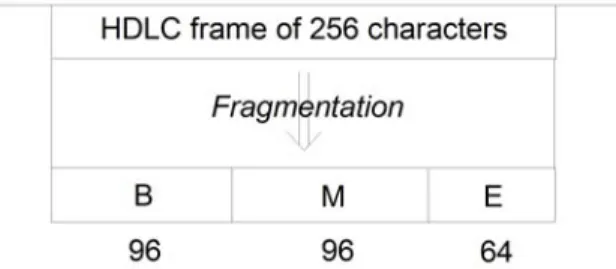
There are six types of traffic cells:
• BEGIN: First cell of a long frame (more than 96 characters) • MIDDLE: Middle cell of a long frame
• END: Last cell of a good frame • ABORT: Last cell of a bad frame
• COMPLETE: The only cell of a small frame (96 characters or less) • VARIABLE: A compressed, variable-length cell.
For example, a long frame will be fragmented into the following cells if it is a good frame:
Through fragmentation, the NetPerformer is able to reduce internal delays in three ways: • Compression and multiplexing can start as soon as the first cell is received. The
NetPerformer does not have to wait for the end of frame. This reduces transmis-sion delay to the time needed to receive and cut a single cell.
• Fallback transmit and receive clocks. If the port or channel is in fallback mode, the NetPerformer reduces the transmitter speed to an appropriate fallback speed when the number of characters left in an incompletely fragmented frame falls below a pre-defined threshold. Fallback is explained further on “Fallback Speed” on page 1-10.
• Early transmission. The NetPerformer starts transmitting frames to the connected device as soon the first few cells are delivered to the transmitter, even if the frame has not been fully fragmented yet. The transmission start level is explained on “Transmission Start Level” on page 1-13.
1.4 Data Compression
If traffic levels are high, NetPerformer applies a dynamic data compression algorithm to the cell contents for increased throughput. After compression, each cell contains the amount of data required to maintain a smooth, delay-free flow. Cells do not have to be full before they are transmitted.
Data compression improves bandwidth utilization, which results in reduced
telecommunications costs. It is applied to all protocols that analyze the traffic in terms of frames.
NOTE: Voice compression algorithms operate independently of data compression, and use DSPs for processing. Refer to the Digital Voice module of this docu-ment series.
The built-in data compressor on the NetPerformer can enhance the throughput of a composite link from 100% to 400%. The actual compression ratio achieved depends on the type of data being transferred and the amount of traffic on the link. It is usually between 2 and 4 (refer to “Checking WAN Link Status” on page 7-1).
The NetPerformer compressor processes the cells that were produced during fragmentation, in the following way:
• First, it carries out run-length encoding on the contents of each cell, replacing identical characters with an escape code.
• Then it builds a dynamic dictionary for each port, using the most frequently encountered character strings.
• It then assigns a Huffman code to each common string, and • Replaces the character strings with these codes.
Decompression is carried out by the data compressor in the destination NetPerformer unit. It replaces the Huffman codes with the original character strings, and decodes the escape codes as the original characters.
1.5 Multiplexing and Cell Relay Transmission
Using a process called Programmable Variable Cell Relay (PVCR), the NetPerformer sends the individual, variable-sized cells resulting from fragmentation and compression over the high-speed link. Delay-sensitive cells such as voice and fax go first. User-defined criteria determine traffic prioritization for LAN and legacy data. Refer to the Quality of Service (QoS) module of this document series.
The mix of high and low-priority cells ensures that, before a non-sensitive frame is sent, a delay-sensitive frame has been completely transferred to the remote device. This avoids interruptions in voice/fax traffic and session timeouts for data traffic such as SNA/SDLC. The NetPerformer uses an advanced statistical multiplexing technique that combines voice, fax and data from all active input ports and channels, and sends the combined traffic over the network via one or more composite links.
• When multiple links are available, load balancing ensures that an equal traffic weight is transmitted over all available links. This feature is described more fully in “Load Balancing” on page 2-2.
• A multiple link configuration also allows for automatic link backup, which provides additional reliability in case of link failure. See “Automatic Dial Backup” on page 2-5.
• Through Bandwidth On Demand, multiple links can be activated and deacti-vated automatically according to current traffic levels and bandwidth needs. This is ideal for applications requiring varying bandwidth levels. See “Bandwidth On Demand” on page 2-7.
• You can also define a range of different link connection scenarios for automatic time-of-day connect, building a schedule that mimics your peak and minimum traffic times. See “Schedule Operation” on page 2-9 for an example of how this works, and “Schedule for Automatic Link Activation” on page 5-1 for configura-tion details.
NetPerformer WAN links use a proprietary level 2 synchronous protocol called PVCR (Programmable Variable Cell Relay) and include a proprietary level 3 protocol.
• Level 2 layer: Responsible for retransmitting frames in case of errors on the links (e.g. for SNA devices). Also used when reliable asynchronous transmission is required.
When the link detects errors on cells destined for a transparent user port, the Net-Performer resets all queues for that port, resynchronizes the compressor and then resumes transmission.
• Level 3 layer: Includes flow control and traffic congestion procedures (see
“Intelligent Congestion Control” on page 1-10). Also responsible for
establish-ing and maintainestablish-ing up to 64 channels in an SNA/SDLC application, one per SNA device (PU).
The composite link carries HDLC frames, with multiple cells in each frame. The frame size on the link is limited to 1024 bytes.
NOTE: This has no bearing on the frame size permitted on transparent user ports or channels configured with the HDLC protocol.
The NetPerformer at the remote end demultiplexes the cells and uses the cell numbering to sort the cells into their original order. It reconstructs the original frames from this cell sequence, and transmits them to the destination devices.
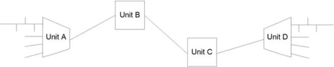
1.6 Mesh Topology
NetPerformer nodes can be connected in a WAN mesh topology. In the application represented in Figure 1-3, source unit A and destination unit D perform protocol sorting, fragmentation, compression/decompression, multiplexing/demultiplexing and cell relay transmission. The intermediary units B and C perform cell relay transmission only.
1.7 Prioritization of Voice/Fax Transmissions
The NetPerformer is well suited for handling voice and fax traffic, due to its ability to prioritize traffic, reduce delays and control traffic congestion. When data transmission is cell-based, the frame does not have to be completely processed at any location before changing to a new virtual path. The result is that latency and overhead are reduced to a minimum, producing shorter transmission delays. This is essential to satisfactory voice and fax communications.
Due to the delay-sensitive nature of voice and fax transmissions, it is essential that they be prioritized to avoid the generation of delays. All voice/fax traffic entering a NetPerformer channel is automatically given high-priority status with respect to data from other sources. This ensures guaranteed bandwidth access in a shared network environment, and an uninterrupted flow from source to destination.
NOTE: Voice/fax traffic can be assigned to a specific priority class if desired. For details, refer to the Quality of Service (QoS) module of this document series.
Each NetPerformer along the virtual connection path selects a virtual channel according to the priority class assigned to that virtual connection. In this way, the high priority of voice/ fax traffic can be maintained uniformly from source to destination.
Each NetPerformer unit monitors its transmit queue for the priority level of the cells that are received. When high-priority cells arrive, they are expedited to the next NetPerformer on the virtual path before processing the lower priority cells. Lower-priority cells are buffered until the higher-priority voice and fax cells are sent. This also guarantees voice/ fax prioritization throughout the network.
1.8 Intelligent Congestion Control
The NetPerformer is equipped with intelligent congestion control that prevents adverse network situations from interfering with delay-sensitive traffic such as voice
communications.
Using Memotec’s Virtual Connections technology, traffic can be sent from the source NetPerformer unit over several hops, or intervening NetPerformers, to reach the
destination unit. The best route is always chosen, and rerouting is performed automatically through simple routing table updates. As a result, the network topology is highly flexible and adaptable to congestion.
Delays tend to get higher as a virtual path gets longer, each hop typically adding a 10 ms delay. If any NetPerformer along the virtual connection detects congestion while it is transmitting, it automatically retains more data in its buffers to ease the flow.
The turnaround time for the NetPerformer is typically 150 ms across a Wide Area Network. This is significantly better than satellite service, which has a typical latency of 250 ms. Given that the human tolerance for voice delay is about 500 ms, the processing speed of the NetPerformer produces satisfactory results even when congestion is encountered.
The NetPerformer includes flow control techniques to minimize congestion problems and ensure maximum efficiency of the transmitter and receiver at all times. These techniques include:
• Fallback speed of the transmit and receive clocks, and
• Early frame transmission based on the Transmission start level.
1.8.1
Fallback Speed
The NetPerformer supports fallback for data received over a transparent user port (non-PVCR) under the following conditions:
• The transparent user port is a built-in serial port
Digital channels and ports on the Dual Serial interface card do not support fall-back.
• The NetPerformer controls both the transmit and receive clocks on the port (DCE port in internal clocking mode)
With DCE internal clocking, the NetPerformer can set the port speed (normal or fallback) depending on current traffic conditions (uncongested or congested, respectively).
• The port is not configured with an asynchronous or passthrough protocol ( T-ASYNC, R-ASYNC or PASSTHRU), and
• The equipment connected to the port supports fallback speeds.
Fallback is enabled or disabled with the Fallback speed port parameter. However, the actual fallback speed is not configurable. The NetPerformer determines the appropriate fallback speed automatically from the combined speed of all WAN links that carry traffic
to the destination unit.
The NetPerformer provides two independent clocks: one for the receiver (the receive clock) and one for the transmitter (the transmit clock).
NOTE: When fallback is applied on the receive clock, the speed of the transmit clock is not affected. Likewise, when fallback is applied on the transmit clock, the receive clock is not affected.
Fallback on Receive Clock
Congestion can occur on the WAN links when the NetPerformer transmits data to the remote side. This congestion is caused by a low compression ratio or too much traffic queued by the user ports. When congestion occurs, a burst of data on a user port will be stored in the NetPerformer receiver queue.
However, if the data burst size exceeds the capacity of the receiver queue, that data will be lost. This situation is called a receiver overrun. When a receiver overrun occurs, the NetPerformer requests the attached equipment to retransmit the data.
NOTE: To determine whether overruns have occurred on a particular port, execute the Display Errors (DE) command. Refer to “Displaying WAN Link Errors” on page 7-7.
Overruns occur when the user port speed is too high for current capabilities of all WAN links to the destination unit. To prevent overruns, the NetPerformer slows down the receive clock on the user port to the fallback speed, allowing the WAN links to catch up to the traffic flow.
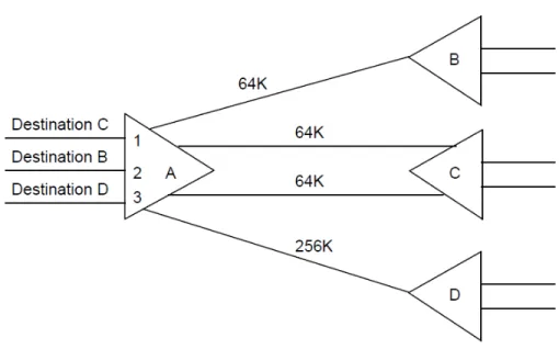
As mentioned earlier, the fallback speed is adjusted automatically to the current traffic situation. In most situations, the NetPerformer sets the fallback to one half of the sum of the speeds of all WAN links to the same destination unit.
NOTE: On some legacy NetPerformer products the fallback speed is not calculated automatically. On these products, you must set the Fallback speed to an appropriate bit rate for your application.
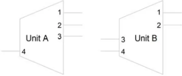
In the example above, the fallback speeds on ports 1 to 3 are calculated as follows:
How it works: When the Fallback speed port parameter is enabled, the receiver reduces its speed if the number of characters in the receiver queue exceeds a configurable threshold (the Transmission start level port parameter). During this time, the amount of data transmitted on the links exceeds the amount of data received on the port, and the congestion situation is resolved before the user port receiver queue becomes full. This avoids both data loss and the delays due to retransmissions. The user port returns to its normal speed when the number of characters in the receiver queue falls below the Transmission start level.
Figure 1-4: Using Fallback Speed for Flow Control
Port Number on
Unit “A” Destination Unit
Link(s) to
Destina-tion Sum of Link Speeds
Fallback Speed (1/2 the Sum of Link Speeds)
1 C A - C (dual link) 128K 64K
2 B A - B (single link) 64K 32K
3 D A - D (single link) 256K 128K
Fallback on Transmit Clock
Fallback is applied to the transmit clock to prevent transmitter underruns. Underruns occur when frames arrive too slowly from the remote unit, so that the user port transmits the beginning part of the frame before it has received the end of the frame. When an underrun occurs on the transmitter, the current frame is aborted.
NOTE: To determine whether underruns have occurred on a particular port, execute the Display Errors (DE) command. Refer to “Displaying WAN Link Errors” on page 7-7.
To prevent underruns, the transmitter is slowed down to the fallback speed, which reduces the rate that data is received from the WAN link.
How it works: When the Fallback speed port parameter is enabled, the user port transmitter reduces its speed if the number of characters of an incomplete frame in the output queue goes below the current value of the Transmission start level parameter (see next section). During this time, the port transmission rate is slower than the rate at which data is received from the WAN links, which allows the port to receive the end of frame before the beginning part of the frame has been completed transmitted to the attached equipment. Once the frame is sent, the transmitter returns to normal speed.
1.8.2
Transmission Start Level
A NetPerformer user port can start transmitting a frame as soon as a specified number of characters have been received from the WAN link. Transmission delays are reduced when the transmitter can start before the incoming frame has been completely received.
Transmission flow control must also be applied to avoid underruns and ensure a smooth traffic flow. Refer to “Fallback Speed” on page 1-10.
To specify the number of characters that must be received before the port can start transmitting a frame, set the Transmission start level port parameter.
NOTE: The user port must be in DCE internal clocking mode, and the attached equip-ment must support this feature.
In the port transmitter queue, transmission will start when the Transmission start level is reached or the frame is complete. The transmitter will go into fallback if the frame is incomplete and the receive rate is slow.
Setting the Transmission Start Level
Set the Transmission start level to AUTO if you would like the NetPerformer to start the user port transmitter automatically according to the port clocking mode, speed and fallback speed settings.
If you do not want the NetPerformer to control the Transmission start level automatically, you need to consider:
• The user port clocking mode
- Set Transmission start level to MAX if the port is not in DCE internal clocking mode. The transmitter will start only when the complete frame has been received from the remote unit.
• Whether Fallback speed is enabled on the port
- Set Transmission start level to MAX if fallback is disabled.
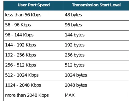
- If fallback is enabled and the user port is in DCE internal clocking mode, set the Transmission start level according to the speed of the port, as shown in Table 1-2.
NOTE: The Transmission start level parameter behaves differently for a Passthrough channel (built-in serial port set to the PASSTHRU protocol). It represents the number of transparent data blocks (rather than characters of an incomplete frame) that the port must accumulate before enabling the transmitter. On a PASSTHRU port, the Transmission start level can be set from a minimum of 3 to a maximum of 12 blocks. Refer to the Legacy Data module of this docu-ment series.
User Port Speed Transmission Start Level
less than 56 Kbps 48 bytes
56 - 96 Kbps 96 bytes
96 - 144 Kbps 144 bytes
144 - 192 Kbps 192 bytes 192 - 256 Kbps 256 bytes 256 - 512 Kbps 512 bytes 512 - 1024 Kbps 1024 bytes 1024 - 2048 Kbps 2048 bytes more than 2048 Kbps MAX
2
2.1 About Multiple Link Capabilities
The NetPerformer supports multiple WAN links with:• Load balancing (see next section)
• Inverse multiplexing (see “Inverse Multiplexing” on page 2-4) • Automatic dial backup (see “Automatic Dial Backup” on page 2-5) • Bandwidth On Demand (see “Bandwidth On Demand” on page 2-7) • Schedule operation (see “Schedule Operation” on page 2-9).
2.2 Load Balancing
The NetPerformer uses a cell balancing method to accomplish load balancing dynamically across multiple WAN links:
• As described in “PowerCell Principle of Operation” on page 1-2, the NetPer-former cuts all frames into small cells, and routes them over the first available link.
• Using dynamic load balancing, the NetPerformer transmits the cells in parallel over all active links.
• Since each cell is routed individually the available bandwidth is maximized and transmission time is reduced as much as possible, resulting in improved response time and throughput.
• The cells are later reassembled in their original frame format by the NetPer-former at the other end.
In some cases static load balancing (rather than dynamic) should be used in order to set a preferred route over multiple dedicated links. This may be required when:
• More than one route is available • The cost is greater than 0
• All available routes are equal in cost
You can set a separate preferred route for each traffic class. When you assign a different preferred route to different classes, you ensure static load balancing of transparent user traffic over all routes. Set the preferred route for a particular class with the Preferred route
parameter, found in the SETUP/CLASS menu. Details are provided in the Quality of Service (QoS) module of this document series.
2.3 Inverse Multiplexing
The multiple link capabilities of the NetPerformer can be used to create an inverse multiplexing application. Inverse multiplexing provides high-speed support using multiple digital circuits. Here are two possible inverse multiplexing applications that can be created on a single NetPerformer:
2.4 Automatic Dial Backup
The NetPerformer includes an automatic dial backup function which provides network security and redundancy in case of link failure. When dial backup is configured between two NetPerformers, a backup link is automatically activated if the dedicated link fails. In typical applications the backup function is controlled from the NetPerformer unit at the central site. A branch site unit is normally responsible for its own site only, although it can be configured to back up other units in the network.
How it works: In case of a line failure on a dedicated WAN link, the NetPerformer unit controlling the backup mechanism can activate a backup link to take over.
• The NetPerformer tries to establish a backup link when it discovers that it has lost contact with a destination that is listed in its PowerCell routing table (refer to “Displaying PowerCell Destinations” on page 7-17).
• A backup link can be configured to backup a specific dedicated WAN link, any dedicated WAN link that fails, or all dedicated WAN links.
NOTE: The dedicated WAN link must go to a destination that has been estab-lished as an entry in the PowerCell routing table.
• The backup link is activated according to its dialing mode setting, for example, by raising the DTR or X.21 COMMAND signal.
- The dialing mode is configured with the WAN link (PVCR port) Dialer parameter (see “Dialer” on page 8-31).
- If the backup link is established by sending a V25bis or AT command to a modem, all links to the lost destination unit must be down before the phone number will be dialed.
• When the backup link comes up, the NetPerformer automatically runs a test to ensure that it is operative.
On a successful test, the traffic load is immediately shared between the backup link and the other active WAN links. In other words, load balancing continues to operate between all active links, whether they are dedicated or backup links.
• When the failed dedicated link comes back up, the NetPerformer detects that the lost destination is now back. It runs another test and enables load balancing with the newly returned link.
• If the dedicated link does not fail during the test period, the NetPerformer deacti-vates the backup link by lowering the DTR or X.21 COMMAND signal.
NOTE: You can also terminate backup manually using the HANG command (see “HANG Command” on page 6-3). In this case the Backup termination
mode parameter on the backup port must be set to MANUAL. For complete details, turn to “Configuring a Backup Link” on page 3-7.
In a Frame Relay application, your network can also include backup PVCs. These PVCs are activated if a line failure occurs on any or all PVCR links or PVCs. For details, refer to the WAN/Frame Relay module of this document series.
2.5 Bandwidth On Demand
Bandwidth On Demand (BOD) allows for automatic activation and deactivation of multiple WAN links according to current traffic needs. With Bandwidth On Demand, the NetPerformer increases the bandwidth when traffic increases, and decreases it when traffic returns to normal levels.
A BOD solution is ideal for applications that require varying bandwidth levels, for example, LANs with traffic bursts. You can design the network to handle the average traffic load, and allow extra bandwidth to be added only when it is needed.
NOTE: Bandwidth On Demand is available on dedicated WAN links only, that is, a serial port or digital channel configured with in the PVCR protocol. For digi-tal channels, some limitations apply (see “Configuring a Bandwidth on Demand Link” on page 3-10).
How it works: In a typical application of Bandwidth On Demand:
• One WAN link is configured for operation over a dedicated line, for example, local port 1 set in PVCR protocol with DEDICATED mode, connected to remote port 1 set in PVCR protocol with DEDICATED mode.
• A second WAN link is configured for operation over switched circuits, for exam-ple, port 2 set in PVCR protocol with BOD-CALL mode, and remote port 2 set in PVCR protocol with ANSWER mode.
• This link is activated only when the bandwidth usage reaches a pre-defined level (configured with the BOD level parameter).
• When the bandwidth usage on the dedicated link (port 1) reaches the BOD level and stays at that level for a pre-defined period (configured with the Delay before BOD call activation parameter), the switched line is automatically activated (port 2).
NOTE: The Delay before BOD call activation allows time for the bandwidth usage to return to normal in case of a brief burst of data.
• The traffic load is shared between the BOD link and all other active WAN links. In other words, load balancing continues to operate between all active links, whether they are dedicated or BOD links.
• When the bandwidth usage decreases to a significantly lower level (about half of the BOD level) and stays at that level for a pre-defined period (configured with the Delay before BOD call deactivation parameter), the switched line is discon-nected.
NOTE: For a BOD link, you cannot choose a Dialer type that uses a dial phone num-ber. You must select a Dialer type that raises the DTR (V.35 and RS-232) or COMMAND (X.21) signal to activate the modem. Refer to “Configuring a Bandwidth on Demand Link” on page 3-10 for complete configuration details.
2.6 Schedule Operation
The NetPerformer real-time clock permits a Schedule that controls a range of different link connection scenarios for automatic time-of-day connect. This Schedule defines the operating mode of each WAN link for a user-specified period of time.
Schedule periods can be configured on a weekly or daily basis, with a total of 10 periods available. To set up a Schedule for your WAN application, use the SETUP/SCHEDULE menu. For details, refer to “Schedule for Automatic Link Activation” on page 5-1.
How it works: In an example Schedule application, three periods are defined on the NetPerformer unit:
• Period 1, for normal business hours, sets the operating mode of - The main WAN link (port 1) to DEDICATED
- The second link (port 2) to Bandwidth On Demand (CALL-BOD)
If traffic becomes heavy, the second link is automatically activated, providing greater bandwidth to the DTE equipment when required during business hours. • Period 2, for evenings, sets the operating mode of
- The main WAN link (port 1) to DEDICATED
- The second link (port 2) to Backup (CALL-BACKUP)
This protects the dedicated link while avoiding long distance charges in the evening.
• Period 3, for nights and weekends, sets the operating mode of - The main WAN link (port 1) to DEDICATED
- The second link (port 2) to INACTIVE
Here, the second link will not take over even if the dedicated link fails. This reflects the network’s reduced bandwidth needs at night and on weekends. • When no periods are enabled, or no enabled period covers the current time, the
NetPerformer uses the default link operating mode for each WAN link (set with the Mode parameter of the PVCR port). For details on configuring the schedule periods, refer to “Schedule for Automatic Link Activation” on page 5-1.
3
3.1 About the WAN Link
On the NetPerformer, a WAN port is any serial port or digital channel configured with the PVCR (Programmable Variable Cell Relay) protocol. Under this protocol, the port or channel behaves like a WAN connection, and sends its output data over the composite link.
NOTE: The type of cable installed at the port is automatically detected by the NetPer-former, and is displayed at the console during WAN link configuration. For complete cabling instructions, consult the Hardware Installation Guide or Quick Setup Guide (legacy products) for your product, available on the NetPerformer Documentation CD.
A WAN connection can be configured on a serial port (including ports built into the base unit and ports on the Dual Serial Port interface card) or a channel on a digital interface card. The PVCR protocol is used.
The PORT or SLOT submenu of the SETUP console command includes all parameters required to configure a WAN connection. If you are using SNMP, all WAN configuration variables are grouped under the ifwan category. For text-based configuration the [ifwan#] heading is used, where # represents the number of the port or channel.
The following sections describe how to configure:
• A dedicated WAN link for PowerCell connections on a serial port (SE/PORT, “Configuring a Dedicated WAN Link” on page 3-4)
• A dedicated WAN link for PowerCell connections on a digital channel (SE/ SLOT/CHANNEL, “Configuring a Dedicated WAN Link on a Digital Channel” on page 3-5)
• A backup link (“Configuring a Backup Link” on page 3-7)
• A Bandwidth on Demand (BOD) link (“Configuring a Bandwidth on Demand Link” on page 3-10)
Backup and BOD links also require Phone profiles. Refer to “Phones for Backup Links” on page 4-1.
• A Wait-User link (“Configuring a Link for Conditioned Activation” on page 3-13) for conditioned activation based on user port activity
• An inactive link (“Deactivating a WAN Link” on page 3-15).
Turn to “Verifying WAN Link Configuration” on page 3-16 for instructions on how to
Console SNMP Text-based Config
SE/PORT (serial port) SE/SLOT (digital channel or dual serial port)
view the current values of all link parameters.
To configure a time schedule for different link connection scenarios, turn to “Schedule for Automatic Link Activation” on page 5-1.
3.2 Configuring a Dedicated WAN Link
A dedicated WAN link can be configured on a serial port (including ports built into the base unit and ports on the Dual Serial Port interface card) or a channel on a digital interface card.
NOTE: On a digital interface card, a dedicated PVCR connection is available with all signaling modes configured on the LINK.
3.2.1
Configuring a Dedicated WAN Link on a Serial Port
To configure a built-in serial port on the base unit as a dedicated WAN link: 1. Enter the menu sequence: SE PORT.
2. Select the Port number.
3. Set the Protocol to PVCR and the Mode to DEDICATED.
4. Change the other port parameters from their default values, if desired.
To configure a serial port on the Dual Serial interface card as a dedicated WAN link: 1. Enter the menu sequence: SE SLOT.
2. Select the Slot number. 3. Select the Channel number.
4. Set the Protocol to PVCR and the Mode to DEDICATED.
5. Change the other port parameters from their default values, if desired.
The parameters presented at the console are identical for the NetPerformer base product and NetPerformer SIP VoIP option.
SE/PORT/#/ PVCR example: in DEDICATED Mode SDM-9230>SE SETUP
Item (BRIDGE/CALLER ID/CLASS/CUSTOM/FILTER/GLOBAL/HUNT/IP/IPX/MAP/ PHONE/
PORT/PU/PPPOE/PPPUSER/PVC/REDUNDANCY/SCHEDULE/SLOT/USER/VLAN, def:BRIDGE) ? PORT
Port number (ETH1/ETH2/CSL/1,def:1) ? PORT 1> Protocol (def:PPP) ? PVCR
PORT 1> Interface...DCE-V35 PORT 1> Clocking mode (def:INTERNAL) ?
PORT 1> Port speed (bps) (1200-6144000,def:56000) ? PORT 1> Mode (def:DEDICATED) ?
PORT 1> IP address (def:000.000.000.000) ?
PORT 1> Subnet mask (number of bits) (0-32,def:0) ? {000.000.000.000}
PORT 1> IP RIP (def:V1) ?
PORT 1> OSPF (def:DISABLE) ?
PORT 1> IP multicast active (def:NO) ? PORT 1> IP multicast protocol (def:NONE) ? PORT 1> NAT enable (def:NO) ?
PORT 1> IPX RIP (def:DISABLE) ? PORT 1> IPX SAP (def:DISABLE) ?
PORT 1> IPX network number (def:00000000) ? PORT 1> Compression (def:YES) ?
PORT 1> Remote unit name (def:) ? CHICAGO-9230 PORT 1> Timeout (ms) (1000-30000,def:1000) ?
PORT 1> Number of retransmission retries (1-1000,def:100) ? PORT 1> Maximum number of voice channels (0-10000,def:10000) ? PORT 1> Maximum Voice Channels If High Priority Data (0-10000,def:10000) ?
PORT 1> Cell Packetization (def:YES) ? PORT 1> Filter (def:ALL) ?
Detailed descriptions of each parameter are provided in the appendix “SE/PORT/#/PVCR Configuration Parameters” on page 8-1.
3.2.2
Configuring a Dedicated WAN Link on a Digital Channel
To configure a digital channel as a dedicated WAN link: 1. Enter the menu sequence: SE SLOT.2. Select the Slot number.
3. Enter CHANNEL at the Item prompt.
4. Select the Channel number, e.g. 102, where the first digit indicates the slot and the last two digits indicate the channel.
5. Set the Protocol to PVCR. 6. Set the Mode to DEDICATED.
7. Change the other port parameters from their default values, if desired.
SE/SLOT/#/ CHANNEL/ PVCR example: in DEDICATED Mode SDM-9230>SE SETUP
Item (BRIDGE/CALLER ID/CLASS/CUSTOM/FILTER/GLOBAL/HUNT/IP/IPX/MAP/ PHONE/
PORT/PU/PPPOE/PPPUSER/PVC/REDUNDANCY/SCHEDULE/SLOT/USER/VLAN, def:BRIDGE) ? SLOT
SLOT> Slot number (1/2/3,def:1) ? Item (LINK/CHANNEL,def:CHANNEL) ?
SLOT> Channel Number (101-124/ALL,def:115) ? PORT 115> Protocol (def:PPP) ? PVCR
PORT 115> Timeslot (def:15) ?
PORT 115> Number of consecutive timeslots (1-9,def:1) ? PORT 115> DS0 speed (bps) (def:64000) ?
PORT 115> Mode (def:DEDICATED) ?
PORT 115> IP address (def:000.000.000.000) ?
PORT 115> Subnet mask (number of bits) (0-32,def:0) ? {000.000.000.000}
PORT 115> IP RIP (def:V1) ?
PORT 115> IP RIP TX/RX (def:DUPLEX) ? PORT 115> OSPF (def:DISABLE) ? ?
PORT 115> IP multicast active (def:NO) ? PORT 115> IP multicast protocol (def:NONE) ? PORT 115> NAT enable (def:NO) ?
PORT 115> IPX RIP (def:DISABLE) ? PORT 115> IPX SAP (def:DISABLE) ?
PORT 115> IPX network number (def:00000000) ? PORT 115> Compression (def:YES) ?
PORT 115> Remote unit name (def:) ? CHICAGO-9230 PORT 115> Timeout (ms) (1000-30000,def:1000) ?
PORT 115> Number of retransmission retries (1-1000,def:100) ? PORT 115> Maximum number of voice channels (0-10000,def:10000) ? PORT 115> Maximum Voice Channels If High Priority Data (0-10000,def:10000) ?
PORT 115> Cell Packetization (def:YES) ? PORT 115> Filter (def:ALL) ?
For details concerning the Timeslot, Number of consecutive timeslots and DS0 speed (bps) parameters, refer to the Digital Data module of this document series.
For details on the other parameters in this example, refer to the appendix “SE/PORT/#/ PVCR Configuration Parameters” on page 8-1.
NOTE: Unlike a serial port, a digital channel defined as a WAN link (with the PVCR protocol) cannot be configured in ANSWER, CALL-BKUP, CALL-BOD, or WAIT USER mode when the Signaling mode on the digital LINK contains cer-tain values. Refer to the following sections for details.
3.3 Configuring a Backup Link
A backup link can be established between two PVCR ports or channels if one is
configured to activate a call when a link goes down (CALL-BKUP mode) and the other is configured to answer the call (ANSWER mode).
3.3.1
Limitations on Digital Channels
• A digital channel cannot be used as either the calling or answering side of a backup link when the Signaling mode on the digital LINK is configured with CAS, ROB BIT, transparent (TRSP-ORIG or TRSP-ANSW) or no signaling (NONE).
Under any of these Signaling modes, a PVCR channel can be set to be DEDI-CATED or INACTIVE mode only.
• For a digital channel, CALL-BKUP mode is available only when the Signaling mode on the LINK is set to EURO-ISDN, QSIG, INS-NET, NTT, KDD, NI1, NI2, 4ESS, 5ESS, DMS100 or QSIG.
For further information on configuring the LINK of a digital interface card, refer to the Digital Data or Digital Voice module of this document series.
3.3.2
Calling Side of the Backup Link
To configure the port or channel on the calling side of the backup link: 1. Set the Protocol to PVCR
2. Set the Mode to CALL-BKUP
NOTE: As an alternative, you can define the backup link as part of a Schedule opera-tion, using the Operating mode parameter of the SETUP/SCHEDULE menu. Refer to “Schedule for Automatic Link Activation” on page 5-1.
3. Specify which dedicated WAN link or links this port backs up, using the Port to back parameter
4. Set the dialer type with the Dialer parameter (see “Dialer” on page 8-31).
NOTE: If you choose a Dialer type that requires a dial phone number, configure this number with the SETUP/PHONE menu. Refer to “Phones for Backup Links” on page 4-1.
SE/PORT/#/ PVCR example: in CALL-BKUP Mode SDM-9230>SE SETUP
Item (BRIDGE/CALLER ID/CLASS/CUSTOM/FILTER/GLOBAL/HUNT/IP/IPX/MAP/ PHONE/
PORT/PU/PPPOE/PPPUSER/PVC/REDUNDANCY/SCHEDULE/SLOT/USER/VLAN, def:BRIDGE) ? PORT
Port number (ETH1/ETH2/CSL/1,def:1) ? PORT 1> Protocol (def:PVCR) ?
PORT 1> Interface...DCE-V35 PORT 1> Clocking mode (def:INTERNAL) ?
PORT 1> Port speed (bps) (1200-6144000,def:56000) ? PORT 1> Mode (def:ANSWER) ? CALL-BKUP
PORT 1> Backup termination mode (def:AUTOMATIC) ?
PORT 1> Delay before call activation (s) (1-1000,def:10) ? PORT 1> Delay before call deactivation (s) (1-1000,def:120) ? PORT 1> Call activation timer (s) (30-1000,def:30) ?
PORT 1> Port to back (def:ANY) ? PORT 1> Dialer (def:DTR) ?
PORT 1> IP address (def:000.000.000.000) ?
PORT 1> Subnet mask (number of bits) (0-32,def:0) ? {000.000.000.000}
PORT 1> IP RIP (def:V1) ?
PORT 1> IP RIP TX/RX (def:DUPLEX) ? PORT 1> OSPF (def:DISABLE) ?
PORT 1> IP multicast active (def:NO) ? PORT 1> IP multicast protocol (def:NONE) ? PORT 1> NAT enable (def:NO) ?
PORT 1> IPX RIP (def:DISABLE) ? PORT 1> IPX SAP (def:DISABLE) ?
PORT 1> IPX network number (def:00000000) ? PORT 1> Compression (def:YES) ?
PORT 1> Remote unit name (def:) ? CHICAGO-9230 PORT 1> Timeout (ms) (1000-30000,def:1000) ?
PORT 1> Number of retransmission retries (1-1000,def:100) ? PORT 1> Maximum number of voice channels (0-10000,def:10000) ? PORT 1> Maximum Voice Channels If High Priority Data (0-10000,def:10000) ?
PORT 1> Cell Packetization (def:YES) ? PORT 1> Filter (def:ALL) ?
For detailed descriptions of all parameters specific to a CALL-BKUP connection, refer to “CALL-BKUP Mode” on page 8-28 of the appendix SE/PORT/#/PVCR Configuration Parameters.
3.3.3
Answering Side of the Backup Link
To configure the port or channel on the answering side of the backup link: 1. Set the Protocol to PVCR
2. Set the Mode to ANSWER
3. Set the Dialer to the same value configured on the CALL-BKUP port at the other end of the connection (see “Dialer” on page 8-31).
NOTE: Not all digital channels can be configured as the answering side. Refer to “Limitations on Digital Channels” on page 3-7.
NOTE: The Remote unit name does not need to be specified on an ANSWER port.
The parameters presented at the console are identical for the NetPerformer base product and NetPerformer SIP VoIP option.
SE/PORT/#/ PVCR example: in ANSWER Mode SDM-9230>SE SETUP
Item (BRIDGE/CALLER ID/CLASS/CUSTOM/FILTER/GLOBAL/HUNT/IP/IPX/MAP/ PHONE/
PORT/PU/PPPOE/PPPUSER/PVC/REDUNDANCY/SCHEDULE/SLOT/USER/VLAN, def:BRIDGE) ? PORT
Port number (ETH1/ETH2/CSL/1,def:1) ? PORT 1> Protocol (def:PVCR) ?
PORT 1> Interface...DCE-V35 PORT 1> Clocking mode (def:INTERNAL) ?
PORT 1> Port speed (bps) (1200-6144000,def:56000) ? PORT 1> Mode (def:DEDICATED) ? ANSWER
PORT 1> Dialer (def:DTR) ?
PORT 1> IP address (def:000.000.000.000) ?
PORT 1> Subnet mask (number of bits) (0-32,def:0) ? {000.000.000.000}
PORT 1> IP RIP (def:V1) ?
PORT 1> IP RIP TX/RX (def:DUPLEX) ? PORT 1> OSPF (def:DISABLE) ?
PORT 1> IP multicast active (def:NO) ? PORT 1> IP multicast protocol (def:NONE) ? PORT 1> NAT enable (def:NO) ?
PORT 1> IPX RIP (def:DISABLE) ? PORT 1> IPX SAP (def:DISABLE) ?
PORT 1> IPX network number (def:00000000) ? PORT 1> Compression (def:YES) ?
PORT 1> Remote unit name (def:) ? CHICAGO-9230 PORT 1> Timeout (ms) (1000-30000,def:1000) ?
PORT 1> Number of retransmission retries (1-1000,def:100) ? PORT 1> Maximum number of voice channels (0-10000,def:10000) ? PORT 1> Maximum Voice Channels If High Priority Data (0-10000,def:10000) ?
PORT 1> Cell Packetization (def:YES) ? PORT 1> Filter (def:ALL) ?
NOTE: For details on the parameters in this example, refer to the appendix “SE/ PORT/#/PVCR Configuration Parameters” on page 8-1.
3.4 Configuring a Bandwidth on Demand Link
A Bandwidth on Demand (BOD) link can be established between two PVCR ports or channels if one is configured to activate a call when traffic becomes heavy (CALL-BOD mode) and the other is configured to answer the call (ANSWER mode).
NOTE: Bandwidth On Demand can only be used to supplement a dedicated WAN link.
3.4.1
Limitations on Digital Channels
• A digital channel cannot be used as either the calling or answering side of a BOD link when the Signaling mode on the digital LINK is configured with CAS, ROB BIT, transparent (TRSP-ORIG or TRSP-ANSW) or no signaling (NONE). Under any of these Signaling modes, a PVCR channel can be set to be DEDI-CATED or INACTIVE mode only.
• For a digital channel, CALL-BOD mode is available only when the Signaling mode on the LINK is set to EURO-ISDN, QSIG, INS-NET, NTT, KDD, NI1, NI2, 4ESS, 5ESS, DMS100 or QSIG.
For further information on configuring the LINK of a digital interface card, refer to the Digital Data or Digital Voice module of this document series.
3.4.2
Calling Side of the BOD Link
To configure the port or channel on the calling side of the BOD link: 1. Set the Protocol to PVCR
2. Set the Mode to CALL-BOD
NOTE: As an alternative, you can define the BOD link as part of a Schedule opera-tion, using the Operating mode parameter of the SETUP/SCHEDULE menu. Refer to “Schedule for Automatic Link Activation” on page 5-1.
3. Specify which dedicated WAN link or links this port backs up, using the Port to back parameter
4. Set the Dialer to either DTR or X21-L1 (see “Dialer” on page 8-31). Phone number dialing cannot be used to raise a BOD link.
The parameters presented at the console are identical for the NetPerformer base product and NetPerformer SIP VoIP option.
SE/PORT/#/ PVCR example: in CALL-BOD Mode SDM-9230>SE SETUP
Item (BRIDGE/CALLER ID/CLASS/CUSTOM/FILTER/GLOBAL/HUNT/IP/IPX/MAP/ PHONE/
PORT/PU/PPPOE/PPPUSER/PVC/REDUNDANCY/SCHEDULE/SLOT/USER/VLAN, def:BRIDGE) ? PORT
Port number (ETH1/ETH2/CSL/1,def:1) ? PORT 1> Protocol (def:PVCR) ?
PORT 1> Interface...DCE-V35 PORT 1> Clocking mode (def:INTERNAL) ?
PORT 1> Port speed (bps) (1200-6144000,def:56000) ? PORT 1> Mode (def:CALL-BKUP) ? CALL-BOD
PORT 1> Delay before BOD call activation (s) (1-1000,def:120) ? PORT 1> Delay before BOD call deactivation (s) (1-1000,def:120) ? PORT 1> BOD level (%) (5-95,def:80) ?
PORT 1> Delay before call activation (s) (1-1000,def:10) ? PORT 1> Delay before call deactivation (s) (1-1000,def:120) ? PORT 1> Call activation timer (s) (30-1000,def:30) ?
PORT 1> Port to back (def:ANY) ? PORT 1> Dialer (def:DTR) ?
PORT 1> IP address (def:000.000.000.000) ?
PORT 1> Subnet mask (number of bits) (0-32,def:0) ? {000.000.000.000}
PORT 1> IP RIP (def:V1) ?
PORT 1> IP RIP TX/RX (def:DUPLEX) ? PORT 1> OSPF (def:DISABLE) ?
PORT 1> IP multicast active (def:NO) ? PORT 1> IP multicast protocol (def:NONE) ? PORT 1> NAT enable (def:NO) ?
PORT 1> IPX RIP (def:DISABLE) ? PORT 1> IPX SAP (def:DISABLE) ?
PORT 1> IPX network number (def:00000000) ? PORT 1> Compression (def:YES) ?
PORT 1> Remote unit name (def:) ? CHICAGO-9230 PORT 1> Timeout (ms) (1000-30000,def:1000) ?
PORT 1> Number of retransmission retries (1-1000,def:100) ? PORT 1> Maximum number of voice channels (0-10000,def:10000) ? PORT 1> Maximum Voice Channels If High Priority Data (0-10000,def:10000) ?
PORT 1> Cell Packetization (def:YES) ? PORT 1> Filter (def:ALL) ?
For detailed descriptions of all parameters specific to a CALL-BOD connection, refer to “CALL-BOD Mode” on page 8-33 of the appendix SE/PORT/#/PVCR Configuration Parameters.
3.4.3
Answering Side of the BOD Link
To configure the port or channel on the answering side of the BOD link:
1. Set the Protocol to PVCR and the Mode to ANSWER, as described for the answering side of a backup link (see “Answering Side of the Backup Link” on page 3-8) 2. Set the Dialer parameter to the same value as the Dialer on the CALL-BOD port at
the other end of the connection (see “Dialer” on page 8-31).
NOTE: Not all digital channels can be configured as the answering side. Refer to “Limitations on Digital Channels” on page 3-10.
3.5 Configuring a Link for Conditioned Activation
The activation of a NetPerformer WAN link can be conditioned by the presence of active modem signals on a transparent user port (Protocol set to HDLC, T-ASYNC, R-ASYNC, BSC, COP or PASSTHRU) that sends data via this link.
• For a DCE connection, the DCD signal must be present. • For a DTE connection, the DTR signal must be present. To configure a port or channel as a conditioned link:
1. Set the Protocol to PVCR 2. Set the Mode to WAIT USER
3. Change the other parameters from their default values, if desired. These are the same parameters as those for DEDICATED mode (see “Configuring a Dedicated WAN Link” on page 3-4).
If a WAN link is configured in WAIT USER mode, you can bring the link up by activating the modem signals on the transparent user port. When the NetPerformer detects the modem signals, it immediately activates the link required to transmit the data to its destination. When you deactivate the modem signals, the NetPerformer responds by disconnecting the link.
3.5.1
Limitations on Digital Channels
• A digital channel cannot be used as a WAIT USER conditioned link when the Signaling mode on the digital LINK is configured with CAS, ROB BIT, transpar-ent (TRSP-ORIG or TRSP-ANSW) or no signaling (NONE).
Under any of these Signaling modes, a PVCR channel can be set to be DEDI-CATED or INACTIVE mode only.
• For a digital channel, WAIT USER mode is available only when the Signaling mode on the LINK is set to EURO-ISDN, QSIG, INS-NET, NTT, KDD, NI1, NI2, 4ESS, 5ESS, DMS100 or QSIG.
For further information on configuring the LINK of a digital interface card, refer to the Digital Data or Digital Voice module of this document series.
SE/PORT/#/ PVCR example: in WAIT USER Mode SDM-9230>SE SETUP
Item (BRIDGE/CALLER ID/CLASS/CUSTOM/FILTER/GLOBAL/HUNT/IP/IPX/MAP/ PHONE/
PORT/PU/PPPOE/PPPUSER/PVC/REDUNDANCY/SCHEDULE/SLOT/USER/VLAN, def:BRIDGE) ? PORT
Port number (ETH1/ETH2/CSL/1,def:1) ? PORT 1> Protocol (def:PVCR) ?
PORT 1> Interface...DCE-V35 PORT 1> Clocking mode (def:INTERNAL) ?
PORT 1> Port speed (bps) (1200-6144000,def:56000) ? PORT 1> Mode (def:INACTIVE) ? WAIT USER
PORT 1> Subnet mask (number of bits) (0-32,def:0) ? {000.000.000.000}
PORT 1> IP RIP (def:V1) ?
PORT 1> IP RIP TX/RX (def:DUPLEX) ? PORT 1> OSPF (def:DISABLE) ?
PORT 1> IP multicast active (def:NO) ? PORT 1> IP multicast protocol (def:NONE) ? PORT 1> NAT enable (def:NO) ?
PORT 1> IPX RIP (def:DISABLE) ? PORT 1> IPX SAP (def:DISABLE) ?
PORT 1> IPX network number (def:00000000) ? PORT 1> Compression (def:YES) ?
PORT 1> Remote unit name (def:CHICAGO-9230) ? PORT 1> Timeout (ms) (1000-30000,def:1000) ?
PORT 1> Number of retransmission retries (1-1000,def:100) ? PORT 1> Maximum number of voice channels (0-10000,def:10000) ? PORT 1> Maximum Voice Channels If High Priority Data (0-10000,def:10000) ?
PORT 1> Cell Packetization (def:YES) ? PORT 1> Filter (def:ALL) ?
NOTE: For details on the parameters in this example, refer to “DEDICATED Mode” on page 8-2 of the appendix SE/PORT/#/PVCR Configuration Parame-ters.
3.6 Deactivating a WAN Link
In Inactive mode the PVCR link is turned off. This mode can be useful when setting up the NetPerformer Schedule function. For further information, refer to “Schedule for Automatic Link Activation” on page 5-1.
To deactivate a WAN port:
• Set the port Protocol to PVCR • Set the Mode to INACTIVE.
The parameters listed are the same as those for DEDICATED mode (see page 3-4). If you define them fully, you can activate the link at a later time by simply changing the value of the Mode parameter from INACTIVE to DEDICATED. This can also be done automatically through the Schedule function.
SE/PORT/#/ PVCR example: in INACTIVE Mode SDM-9230>SE SETUP
Item (BRIDGE/CALLER ID/CLASS/CUSTOM/FILTER/GLOBAL/HUNT/IP/IPX/MAP/ PHONE/
PORT/PU/PPPOE/PPPUSER/PVC/REDUNDANCY/SCHEDULE/SLOT/USER/VLAN, def:BRIDGE) ? PORT
Port number (ETH1/ETH2/CSL/1,def:1) ? PORT 1> Protocol (def:PVCR) ?
PORT 1> Interface...DCE-V35 PORT 1> Clocking mode (def:INTERNAL) ?
PORT 1> Port speed (bps) (1200-6144000,def:56000) ? PORT 1> Mode (def:CALL-BOD) ? INACTIVE
PORT 1> IP address (def:000.000.000.000) ?
PORT 1> Subnet mask (number of bits) (0-32,def:0) ? {000.000.000.000}
PORT 1> IP RIP (def:V1) ?
PORT 1> IP RIP TX/RX (def:DUPLEX) ? PORT 1> OSPF (def:DISABLE) ?
PORT 1> IP multicast active (def:NO) ? PORT 1> IP multicast protocol (def:NONE) ? PORT 1> NAT enable (def:NO) ?
PORT 1> IPX RIP (def:DISABLE) ? PORT 1> IPX SAP (def:DISABLE) ?
PORT 1> IPX network number (def:00000000) ? PORT 1> Compression (def:YES) ?
PORT 1> Remote unit name (def:CHICAGO-9230) ? PORT 1> Timeout (ms) (1000-30000,def:1000) ?
PORT 1> Number of retransmission retries (1-1000,def:100) ? PORT 1> Maximum number of voice channels (0-10000,def:10000) ? PORT 1> Maximum Voice Channels If High Priority Data (0-10000,def:10000) ?
PORT 1> Cell Packetization (def:YES) ? PORT 1> Filter (def:ALL) ?
NOTE: For details on the parameters in this example, see to “DEDICATED Mode” on page 8-2 .
3.7 Verifying WAN Link Configuration
The Display Parameters (DP) command provides a complete list of current values for all configuration parameters.
To display the current values of WAN link configuration parameters: 1. Enter DP at the console command prompt
2. At the Item prompt, enter the name of the submenu of parameters you want to inspect: - PORT: To view the parameters for a built-in serial port. Enter the specific
Port number at the prompt.
- SLOT: To view the parameters for the digital channels or dual serial ports on a specific slot. Enter the Slot number at the prompt.
- ALL: To view all configuration parameters. With this option, all ports and channels are listed. Enter YES at the prompt Wait for <ENTER> after each screen if you would like to view this display one screen at a time.
NOTE: The ALL option also lists all currently active extended parameters.
DP example: with backup link
SDM-9380>DP
DISPLAY PARAMETERS
Item (BRIDGE/CALLER ID/CLASS/CUSTOM/FILTER/GLOBAL/HUNT/IP/IPX/MAP/ PHONE/
PORT/PU/PVC/SCHEDULE/SLOT/USER/VLAN/ALL,def:GLOBAL) ? PORT Port number (ETH/CSL/1/2/3,def:ETH) ? 1
PORT 1> Protocol...PVCR PORT 1> Interface...UNDEFINE PORT 1> Clocking mode...INTERNAL PORT 1> Port speed (bps)...56000 PORT 1> Mode...CALL-BKUP PORT 1> Backup termination mode...AUTOMATIC PORT 1> Delay before call activation (s)...10
PORT 1> Delay before call deactivation (s) ...120 PORT 1> Call activation timer (s)...30 PORT 1> Port to back...ANY PORT 1> Dialer...DTR
PORT 1> IP address...000.000.000.000 PORT 1> Subnet mask (number of bits)...0
{000.000.000.000}
PORT 1> IP RIP...V1 PORT 1> IP RIP TX/RX...DUPLEX PORT 1> OSPF...DISABLE PORT 1> IP multicast active...NO PORT 1> IP multicast protocol...NONE PORT 1> NAT enable...NO PORT 1> IPX RIP...DISABLE PORT 1> IPX SAP...DISABLE PORT 1> IPX network number...00000000
PORT 1> Compression...YES PORT 1> Remote unit name... PORT 1> Timeout (ms)...1000 PORT 1> Number of retransmission retries...100 PORT 1> Maximum number of voice channels...10000 PORT 1> Maximum Voice Channels If High Priority Data 10000 PORT 1> Cell Packetization...YES
4
4.1 Phone Profiles
PVCR ports and channels defined as the calling side of a backup link (Mode set to CALL-BKUP) require phone profiles if their Dialer mode involves dialing a phone number to activate the link. Refer to “Dialer” on page 8-31.
• The phone profile contains all information required to execute the call correctly • The NetPerformer will automatically dial the phone number that is associated
with the desired remote unit
• Both modem and ISDN phone connections are supported.
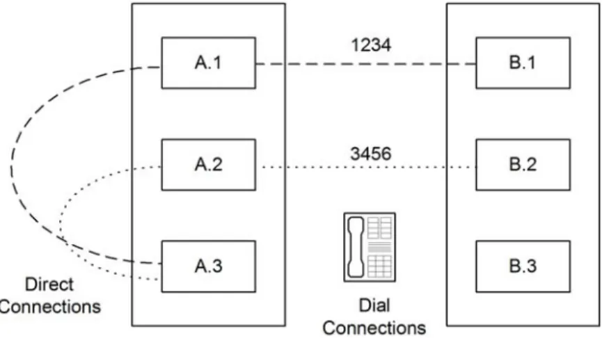
For example, in Figure 4-1, NetPerformer unit A.3 is configured to back up both unit B.1 and unit B.2 using the AT-19200 Dialer mode. To accomplish this, unit A.3 must be configured with two phone profiles, as shown in Table 4-4-1.
Figure 4-1: Phone Profiles for Backup Links
Profile Number Remote Unit Next Hop Cost Phone Number
1 B.1 A.1 1 1234
2 B.2 A.2 1 3456
The PHONE submenu of the SETUP console command includes all parameters required to configure a phone profile. If you are using SNMP, all phone profile configuration
variables are grouped under the phone category. For text-based configuration the [phone#] heading is used, where # represents the number of the phone profile.
Figure 4-2: SETUP/PHONE Path on the CLI Tree
Console SNMP Text-based Config
SE/PHONE phone (category) [phone#] (heading)
4.2 Configuring a Modem Connection
To configure a phone profile for a modem connection: 1. Enter the menu sequence: SE PHONE2. Select the Profile number 3. Enter the Remote unit name
4. Leave the Dialer type at its default value, MODEM 5. Enter the dial Phone number.
SE/PHONE example: with MODEM Dialer type
SDM-9230>SE SETUP
Item (BRIDGE/CALLER ID/CLASS/CUSTOM/FILTER/GLOBAL/HUNT/IP/IPX/MAP/ PHONE/
PORT/PU/PPPOE/PPPUSER/PVC/REDUNDANCY/SCHEDULE/SLOT/USER/VLAN, def:BRIDGE) ? PHONE
Define phone profile for BACKUP links PHONE> Profile number (1-64,def:1) ? PHONE 1> Remote unit (def:) ? CHICAGO-9230 PHONE 1> Next hop (def:) ? MONTREAL-9220 PHONE 1> Cost (0-65534,def:1) ? 2
PHONE 1> Dialer type (def:MODEM) ? PHONE 1> Phone number (def:) ? 4505551212
For details on the other parameters in this example, refer to the appendix “SE/PHONE Configuration Parameters” on page 9-1.