Transactions,SMiRT-23
Manchester, United Kingdom - August 10-14, 2015
Division VI, Paper ID 429
LOCAL MODELING CONSIDERATIONS IN FINITE ELEMENT
ANALYSIS OF NUCLEAR POWER PLANT STRUCTURES
Cagri Ozgur1, Mustafa K. Ozkan1, Evren Ulku2, and James Hays3
1
Project Engineer, Rizzo Associates, USA 2
Technical Director, Structural Engineering, Rizzo Associates, USA 3
Chief Structural Engineer, Rizzo Associates, USA
ABSTRACT
More recently, Nuclear Power Plants (NPP) have started to be built of large, complex steel/concrete (SC) composite structures that are prefabricated off site and assembled on field to maximize manufacturing in a controlled environment and to minimize the construction schedule. However, these complex SC composite structures involve several internal elements that are unique and need special attention for the design and analysis. The SC composite structures are analyzed using sophisticated finite element analysis (FEA) models that are developed to the level of detail necessary to correctly represent the global behavior of the structure. However, these same models do not contain the details necessary to represent the local behavior in the vicinities of platform or equipment supports or random of-plane stiffeners. The out-of-plane influence of local stiffeners may not be generalized with orthotropic section properties since walls and slabs of the structures are typically modelled with coarse 2D shell elements. For such cases, more refined, sub-models of local regions are needed to represent the overall structural behavior adequately and also to increase the fidelity of the model results without having to run large scale analyses. Any simplified geometry and material properties previously employed in a global model may also be represented more rigorously.
This paper provides an overview for the development of local model analyses of SC composite wall structures. The common issues associated with local modeling, including: 2D-shell to 3D-solid transformation; selection and compatibility of boundary conditions around the perimeter of local models; superposition of global and local model analysis results, qualification of the members and post processing the analysis results are discussed.
INTRODUCTION
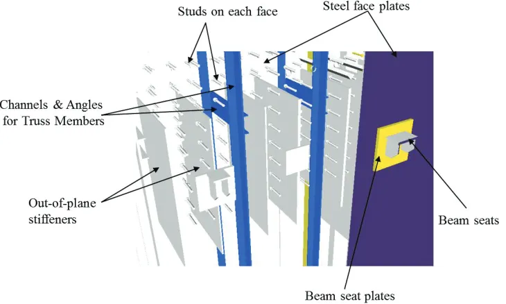
Figure 1 shows a representative SC composite wall section without concrete fill. The SC composite walls are composed of two steel face plates filled with self-consolidating concrete where face plates serve as reinforcement. Shear studs are provided within steel face plates to provide the bond and force transfer between the steel and concrete while maintaining compatibility. Steel face plates are also connected by trusses which stiffen and hold together the face plates during erection and serve as formwork during concrete placement. The truss elements also assure that the concrete reaches 2ඥ݂ᇱ out-of-plane shear capacity by providing interfacial shear transfer capacity between the steel face plates and concrete as well as additional strength similar to that provided by stirrups in reinforced concrete. Additional out-of-plane shear reinforcement i.e., stiffeners are also provided in regions of high out-of-plane demand in terms of steel plates, structural shapes or reinforcing bars which span between steel face plates. At locations where out-of-plane stiffeners are required due to equipment supports, face plates may be thickened to carry the global demand as well as additional local demand.
application of the codes. Because of this complex composite construction, changes to external attachments and other connection design details require more localized investigations and hand calculations may not fully appreciate the complex behavior. The design and analysis of SC composite walls require special attention due to the complex geometry and load transfer mechanism of the structure.
To accurately represent a safety related structure, a global model would need to include the entire building including any internal structures. In the global FEA models, walls and floors would traditionally be modeled with equivalent 2D shell elements, platforms with beam elements and attachments with masses. The meshing would be rather coarse, and local details would be omitted or simplified to capture the overall global behavior. In modular construction, NPP facilities comprise of steel or SC composite walls, platforms, floors, compartments, heavy equipment, and numerous attachments that hang on the walls. NPP facilities are subjected to unique design forces and loads resulting from postulated accidents such as turbine generated missiles and jet forces from high-energy line breaks and from extreme natural hazards such as earthquakes. Even the service reaction forces from heavy equipment or platforms can be on the order of a couple hundred kips applied locally to walls. The traditional FEA models are still well suited and correctly capture the overall global behavior of the structure; however, any discontinuities due to geometry or material, or abrupt changes in stiffness or loading may require mesh refinements or special
analysis techniques that the global models can’t handle since the geometry, load transfer mechanisms and
stiffness distribution of these systems are complex. This paper focuses on the localized analysis of SC composite walls and common issues associated with the FEA analysis.
Figure 1. Representative SC composite wall section without concrete fill.
LOCAL FEA MODELING OF THE SC COMPOSITE WALLS
23rd Conference on Structural Mechanics in Reactor Technology Manchester, United Kingdom - August 10-14, 2015 Division VI
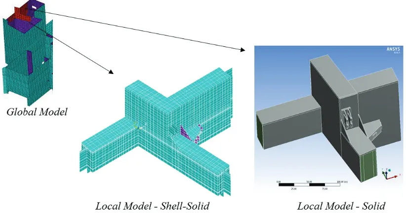
both bending and membrane capabilities. In addition, solid elements are used for the three dimensional modeling of concrete. On the other hand, all members are modeled with solid elements for solid models.
Figure 2. Example of local modeling of SC composite walls.
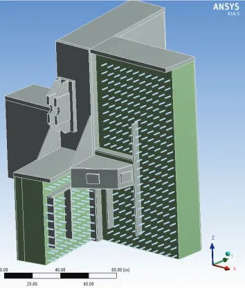
Local FEA models of SC composite walls should be adequately simple to correctly capture the physical behavior with accuracy. The local models typically include steel face plates, out-of-plane stiffeners, internal plates, beam seats, beam seat plates, wall concrete and floors. For more realistic representation of the behavior of the SC wall, welds and studs can be also included in the FEA models. It should be noted that the over-refinement will increase the run time due to increased number of contact surfaces/elements defined in the FEA model. Therefore, common practice of industry is to omit any over-refinement or redundant details. For example, for model simplification, shear studs and structural trusses are typically omitted provided that full bond between steel and concrete is assured by using special contact elements.
Division VI
The FEA meshes should be generated using primarily hex dominant or quadrilateral solid elements, with low skewness and size ratio limitations selected as meshing options to improve accuracy. The FEA mesh development should be also dictated by the element thickness and the need to maintain reasonable aspect ratios for element geometry. The mesh is refined only at parts of the structure where geometry, stresses, or loading change.
Figure 3. FEA solid model with shear studs (Front elements of the wall is hidden for clarity).
INITIAL CONDITIONS
The FEA models utilized for the local models are nonlinear due to material properties and/or contact elements between the different structural members of the wall, such as the contact between the face plates and concrete. The local models are typically developed to qualify the out-of-plane stiffeners and face plates, studs and concrete in the vicinity of a concentrated load due to equipment supports.
Typical industry practice is to neglect the effects of other loads and focus solely on the effects of equipment loads since typical SC composite wall elements such as face plates and concrete are qualified with global models. For this purpose, local models are created to investigate and qualify the elements (e.g. out-of-plane stiffeners) in the vicinity of the equipment supports. Following Saint Venant’s Principle, a
local model should be sized such that any effects due to applied loading become very small at sufficiently large distances from load. Therefore, a local model with end boundaries that are at least two times away from the largest dimension of the out-of-plane stiffeners will be sufficient to capture the distribution of the loads.
23rd Conference on Structural Mechanics in Reactor Technology Manchester, United Kingdom - August 10-14, 2015 Division VI
the boundary conditions and the loads need to be carried over to a local model as applied displacements and loads (see Figure 4, iii). The results of the two configurations are identical (Figure 4, ii & iv). Therefore, displacements of the edge elements and steady-state temperatures of the SC composite wall are carried from the global model to the local models considering the critical load combination.
Initial Condition
(i) (iii)
Final Condition
(ii) (iv)
Figure 4. Example of carrying over results from a global model to a local model.
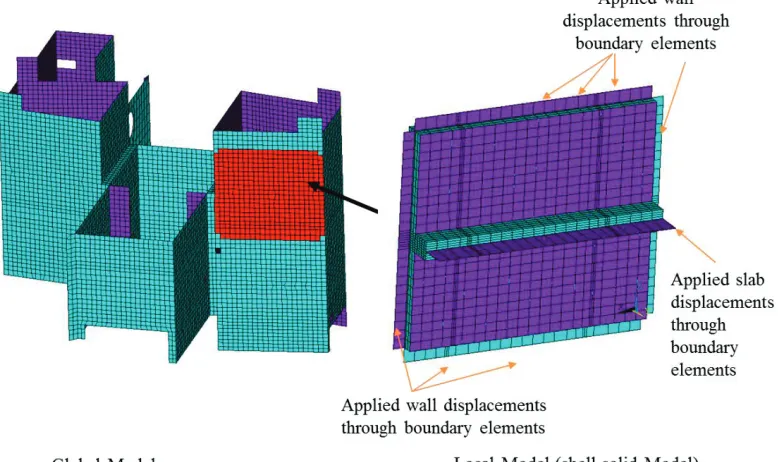
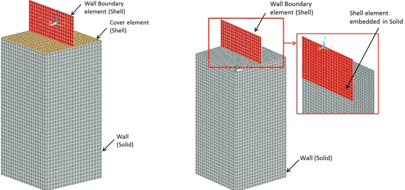
The displacements of the edge elements are typically transferred to the local models by the use of boundary elements as shown in Figure 5. The material and sectional properties of the boundary shell elements should represent the global model properties since 2D elements are utilized to represent the 3D SC composite walls. Displacements obtained from the global model due to the critical load combinations are applied on the boundary elements of the local model. Due to the difference in mesh sizes of the local and global models, the extracted displacements from the global model cannot be applied directly to the local models (i.e. there is not one-to-one nodal relation between boundary nodes of local model and the corresponding nodes on the global model). Therefore, displacements from the global model should be linearly interpolated to obtain displacements at corresponding nodes of the local models. Similar to displacements, the steady-state conditions should be carried from the global model to the local models and should be applied through the thickness of the wall elements.
As already mentioned, shell boundary elements are typically used at the edge of the FEA models to transfer the boundary conditions from the global models. In order to apply displacements in all degrees of freedom (DOFs) appropriately, the boundary elements that are compatible with the corresponding elements in the global model are connected to the edges of the local model elements. However, for the local models, concrete is modeled with solid elements that lack rotational degrees of freedom (DOF) whereas the wall elements representing the global model are represented with shell elements. For such instances, different techniques can be employed to connect 2D shell elements with 3D solids. Traditionally, the shell elements may extend into the 3D solids and be embedded. Alternatively, multipoint constraint equations can be used where shell elements intersect with solid elements or a dummy shell cover element layer can be placed over the solid element faces (Figure 6). It should be noted that different approaches provide results that are comparable at locations sufficiently far from the edge of the solid elements under applied translation and rotation boundary conditions. However, for application of steady state thermal boundary conditions, excessively stiff dummy shell cover elements should be avoided to appropriately represent and remove the effect of artificial stiffness introduced through cover elements on the surface of the solid elements.
(i) use of dummy shell cover elements (ii) extension of 2D shell elements into the 3D solids
23rd Conference on Structural Mechanics in Reactor Technology Manchester, United Kingdom - August 10-14, 2015 Division VI
QUALIFICATION OF SC COMPOSITE WALLS
Steel Members
Face plates are considered as steel reinforcement for concrete and should satisfy the strength design methodology requirements of ACI 349 (2001) for reinforced concrete. Out-of-plane stiffeners should be checked in accordance with Appendix B of ACI 349 (2001). Since the truss elements are used only for
construction purposes they don’t need to be qualified against the equipment support loads.
The equivalent uniaxial yield stress, based on Von Mises theory, is utilized to combine biaxial and triaxial stress components for comparison with allowable stresses. The computation of Von Mises element stress is based on the equation:
ɐൌ ሾሺɐଵെ ɐଶሻଶ ሺɐଵെ ɐଷሻଶ ሺɐଶെ ɐଷሻଶሿǤହ (1)
where σ1, σ2, and σ3, are principal stresses. Von Mises results for all steel elements are compared to the minimum material yield strengths for bending and axial loads. Maximum and minimum principal stresses are also compared to material yield strengths in addition to Von Mises Stresses. For shear, the maximum shear stress is extracted from FEA results. The maximum shear stress is usually computed based on the equation:
ߪ ൌଵଶሺߪଷെ ߪଵሻ (2)
The stresses must remain below the allowable stress values. The allowable stress is defined in AISC N690 (1994) as material yield stress (Fy), times strength reduction factor and times the stress limit coefficient. Note that the stress limit coefficients correspond to the governing load combination presented in Section Q1.5.7.1 of AISC N690 (1994). Strength reduction factors are utilized in accordance with Section Q1.5 of AISC- N690 (1994). Although some steel members of the developed models can meet the requirements of compact sections, the 0.6 strength reduction factor of non-compact sections conservatively can be considered for all members under bending. As noted in Section CQ.1.5.1.7 of AISC N690 (1994), when the use of the stress limit coefficient of 1.6 or 1.7 produces an allowable stress higher than the yield stress of the material, this allowable value, unless limited by other provisions of this code, should be used and the allowable should not be limited to the yield stress value. Therefore, the allowable bending and tension stress is limited to 0.7 x Fu x Z/S for tension plus bending, where Z is the plastic section modulus, S is the section modulus and Fu material ultimate stress. For each out-of-plane stiffener, the plastic section modulus should be calculated for horizontal and vertical axis of the out-of-plane stiffener. For both cases first the plastic neutral axis should be calculated. The plastic neutral axis is defined as the axis that splits the cross section such that the compression force from the area in compression equals to the tension force from the area in tension assuming that the cross-section is fully plastic. Then the plastic section modulus can be expressed as
ൌ ܣൈ ݕ ܣ்ൈ ݕ௧ (3)
where Ac is the total compressive area, AT is the total tensile area, ݕis the distance from the centroid of the compressive area to the plastic neutral axis, and ݕ௧is the distance from the centroid of the tensile area to the plastic neutral axis. Finally, the minimum Z/S ratio can be conservatively selected for the allowable bending and tension stress.
Concrete Members
Division VI
following value of allowable stress for concrete bearing can be considered, using a strength reduction factor of 0.7, Section 9.3 of ACI 349 (2001):
ߪ ൌ ͲǤ ൈ ሺͲǤͺͷ݂ᇱሻ (4)
The allowable compressive strength (ߪ ) should be compared to the 3rd principal stress (minimum principal stress) obtained from the FEA results for the concrete members. With regard to the concrete tensile strength, the cracking limit varies widely. In the Code Commentary, Section R11.4.2 of ACI 318 (1999), the development of cracks in concrete beams is discussed. For beam webs, cracks occur from within the web at the centroidal axis when the principal tensile stress due to shear exceeds a value of approximately 4ඥ݂ᇱ. Flexural cracking initiates on the faces of the beams, and as the cracks progress, shear stresses are increased, and the combined principal tensile stress from shear and flexure produce more cracking. The principal tensile stress magnitude to produce flexure-shear cracks is approximately 6ඥୡᇱ . For the local models, principal tensile stresses are developed from combinations of shear and flexure in the SC composite walls. Since the concrete provides the effective web of the wall section, the lower value of 4ඥୡᇱ can be conservatively adopted as the allowable tension capacity. However, as discussed in the FEA modeling section, tensile resistance of the concrete is conservatively neglected in the modeling by the utilization of the special contact elements. The allowable tensile capacity of concrete can be expressed as
ߪ் ൌ ͲǤͻ ൈ Ͷඥᇱ (5)
The strength reduction factor of 0.9 is applied to this allowable tensile stress. The allowable concrete tensile stress (ߪ் ) should be compared to 1st principal stress (maximum principal stress) obtained from FEA results.
Welds and Studs
The verification welded connections of SC composite walls should be performed according to Section Q1.5.3 of AISC N690 (1994). The allowable stresses specified in AISC N690 (1994) are used for weld verifications. For Partial Joint Penetration (PJP) and Fillet welds, the allowable stress is calculated using Table 2.3 according to AWS D1.1 (2000) or alternatively can be checked from the analysis if the welds are modeled. It should be noted that welds can be represented only when the solid models are utilized. If the studs are modeled and the qualification is desired, the maximum tension force is compared against the maximum tension capacity of the studs.
POST PROCESSING ANALYSIS RESULTS TO AVOID STRESS RISERS (STRESS LINERIZATION)
23rd Conference on Structural Mechanics in Reactor Technology Manchester, United Kingdom - August 10-14, 2015 Division VI
computer-aided methods of analysis, and which may be blunted by confining yielding, must be less than the stipulated allowable stresses. The exercise of engineering judgment is required”. In addition, Section
Q1.5.7 of AISC N690 (1994) allows local yielding and minor distortions under the influence of secondary stresses such as thermal stresses and bending stresses at gross structural discontinuities. Local stress risers do not affect the overall wall structural integrity as the average stress over the entire section is much lower. Therefore, any local high stresses above the allowable stress can be linearized along a path that spans the area of high local stress.
CONCLUSIONS
A brief overview is given for the development of local model analyses for SC composite wall structures and insight to the common issues associated with local modelling, including: 2D-shell to 3D-solid transformations; selection and compatibility of boundary conditions around the perimeter of local models; and superposition of global and local model results, qualification of the members and post processing the analysis results are discussed.
REFERENCES
ACI 349. (2001). “Code Requirements for Nuclear Safety Related Structures (ACI 349-01),” American Concrete Institute, Farmington Hills, MI.
AISC N690. (1994). "Specification for the Design, Fabrication and Erection of Steel Safety Related Structures for Nuclear Facilities (AISC N690-1994)," American Institute of Steel Construction, Chicago, IL.
ACI 318. (1999). “Building Code Requirements for Structural Concrete and Commentary (ACI 318-99),”
American Concrete Institute, Farmington Hills, MI.