ISSN(Online): 2319-8753 ISSN (Print) : 2347-6710
International Journal of Innovative Research in Science,
Engineering and Technology
(A High Impact Factor, Monthly, Peer Reviewed Journal)
Visit: www.ijirset.com
Vol. 7, Issue 12, December 2018
Design and Simulate an OSPF Routing
Protocol based Network on Packet Tracer
Pravesh Kumar Chaudhary1, Ravi Kumar2, Sumit Kaushik3
Senior Technical Officer, ECIL Hyderabad, India 1
Scientist, CERT-In, Delhi, India 2
Network Engineer, Bharti Airtel Ltd., Gurgaon, India 3
ABSTRACT: The aim of this paper is to explore a practical laboratory implementations in terms of structure, content
and overall educational effectiveness. Furthermore, it aims to present the development of a virtual laboratory model that addresses some of the limitations of current solutions through the provision of a high-realistic virtualization environment. With the recent advancements of Internet protocol-based services, packet traffic is becoming the mainstream of data traffic. This has increased the demand for transport network technology that can efficiently accommodate the large capacity of both packet-based and circuit-based traffic while achieving high reliability, sufficient operation, and maintenance capability comparable to that of traditional transport networks such as synchronous digital hierarchy or optical transport networks. In this paper also, a survey has been carried out on previous work dealt with MPLS, SDN networks and different routing algorithms and simulation tools. Also research and design of an OSPF routing based network on packet tracer has been implemented in which trace out packets flow through the routers.
KEYWORDS: Multipath Label Switching (MPLS), Software Defined Network (SDN), Open System Interconnection
(OSI), Routing Protocols, Cisco Packet Tracer.
I. INTRODUCTION
ISSN(Online): 2319-8753 ISSN (Print) : 2347-6710
International Journal of Innovative Research in Science,
Engineering and Technology
(A High Impact Factor, Monthly, Peer Reviewed Journal)
Visit: www.ijirset.com
Vol. 7, Issue 12, December 2018
II. LITERATURE SURVEY
ISSN(Online): 2319-8753 ISSN (Print) : 2347-6710
International Journal of Innovative Research in Science,
Engineering and Technology
(A High Impact Factor, Monthly, Peer Reviewed Journal)
Visit: www.ijirset.com
Vol. 7, Issue 12, December 2018
Table1 IMPORTANT PARAMETERS OF RIP, OSPF, AND EIGRP PROTOCOLS
Protocol RIP OSPF EIGRP
Convergence Time Slow Fast Fast
VSLM No Yes Yes
Bandwidth Usage High Low Low
Resources Usage Low High Low
Multiple path Support No Yes Yes
Scalability No Yes Yes
Patented No No Yes
Non-IP Protocol No No Yes
III.DESIGN &IMPLEMENTATION
Routing protocols should be very well planned and dimensioned for each type of network. They are used according to the choices of the network administrator. The advantage of the routing protocols consists of the fact that they converge very quickly, even though the main route disappears, meaning that these protocols are auto adaptive. Table 2 is showing types & quantities of devices requirement for develop a network model. In this network we are considering three routers with different area & hostname. Branch1 hostname has been assigned to router 1& Head Office has been assigned to the router 2 & Branch2 is assigned Router 3. Branch 1 & 2 have one engineer with PC, Eng1 assigned in branch1 & Wng2 assigned in branch2. Each component of network requires 32-bit IP address so that it can communicate with other devices. In below table it has been assigned IP to each device.
Figure 1:Network model configuration diagram implemented with Packet Tracer Simulation software
Table2 Device Requirements
Device Quantity Model
PC 2 Generic
Routers 3 Cisco 2620XM
Cable-Serial DTE 2 Serial DTE
Cable-Straight-through and cross-over CAT 5e 2 Straight-through and cross-over CAT 5e
Table 3 IP Table of our network
Device /Interface
IP address /Network Address
Subnet Mask Default Gateway Host Name
Fa0/0 10.0.0.1 255.0.0.0 -- Branch1
Se0/1 20.0.0.1 255.0.0.0 Branch1
Se0/1 20.0.0.2 255.0.0.0 Head Office
Se0/0 30.0.0.1 255.0.0.0 --- Head Office
ISSN(Online): 2319-8753 ISSN (Print) : 2347-6710
International Journal of Innovative Research in Science,
Engineering and Technology
(A High Impact Factor, Monthly, Peer Reviewed Journal)
Visit: www.ijirset.com
Vol. 7, Issue 12, December 2018
IV.CONFIGURATIONOFCOMPONENT
Routing is used to trace the path for the network and in this paper we implemented the virtual network model using Cisco packet tracer. As per referring IP from Table3 it has been configured to each device.
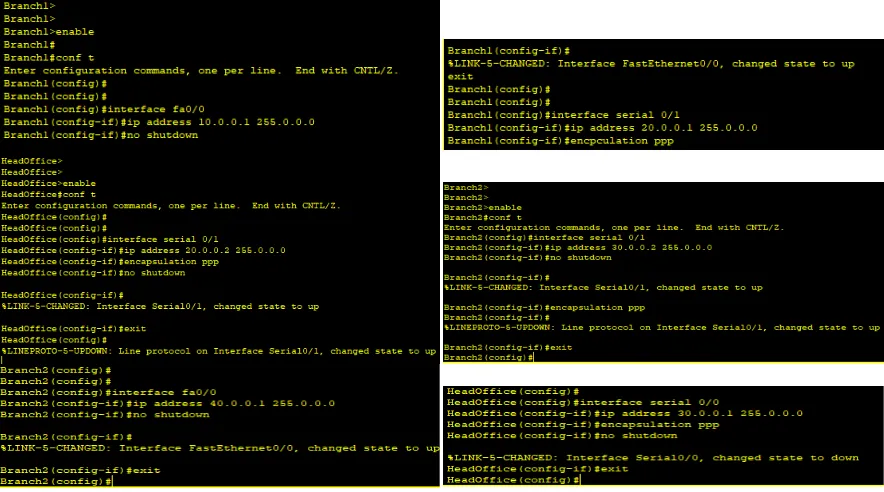
Figure 2 Step by Step description of each command configured on routers
In above Figure 2 Shown configurations IP have been configured on interface of routers. In Router R1interface fastethernet 2/0, address 10.0.0.1 255.0.0.0 configured, same practice has been done at all interface of routers according to assigned IPs.
Configure OSPF routing protocol
ISSN(Online): 2319-8753 ISSN (Print) : 2347-6710
International Journal of Innovative Research in Science,
Engineering and Technology
(A High Impact Factor, Monthly, Peer Reviewed Journal)
Visit: www.ijirset.com
ISSN(Online): 2319-8753 ISSN (Print) : 2347-6710
International Journal of Innovative Research in Science,
Engineering and Technology
(A High Impact Factor, Monthly, Peer Reviewed Journal)
Visit: www.ijirset.com
Vol. 7, Issue 12, December 2018
Figure 3 Step by Step description of each command configured on routers
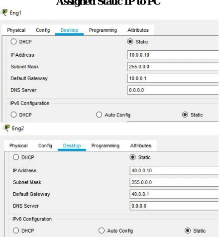
Assigned Static IP to PC
Figure 4 Static IP assigned to the Eng1 & Eng2 PC
With Static IP addressing, addresses are assigned manually so that each device has to its own address with no overlap. When you connect a new device, you would have to select “manual” configuration option and enter in the IP address, the subnet mask, the default gateway and the DNS server. In above figure 4 we have assigned IP address to Eng1 & Eng2 PC.10.0.0.10 & 40.0.0.10 to Eng1 & Eng2 respectively. Here, R3 doesn't know about the area 3 so we have to create virtual link between R1 and R2.After creating virtual link between R1, R2, a virtual link to connect area 3 to area 0 is also created.R2 and R3 get updates about Area 3. Now, check routing table of R3,
V. PARAMETRICANALYSISOFPROPOSED
ISSN(Online): 2319-8753 ISSN (Print) : 2347-6710
International Journal of Innovative Research in Science,
Engineering and Technology
(A High Impact Factor, Monthly, Peer Reviewed Journal)
Visit: www.ijirset.com
Vol. 7, Issue 12, December 2018
destination is able to get an echo reply back to the source within a predetermined time called a timeout. Simulation of topology also possible in packet tracer , It can be simulate and analyzed send & receive packets from host 10.0.0.10 to 40.0.0.10, even it will show total travel time of packets from host to host.
Figure 6 Analyzed Simulation result on routing configured on routers
In above figure 6 shown simulation and analyzed send & receive packets from host 10.0.0.10 to 40.0.0.10, even it will show total travel time of packets from host to host.
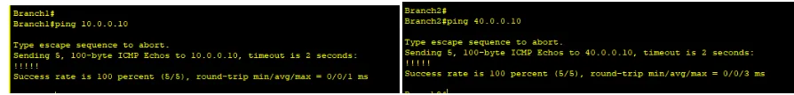
In Below figure 7 shown ping response of Host 10.0.0.10, in which 100% packets send & received at host.
Figure 7 Step by Step description of each command configured on routers
VI.CONCLUSION
ISSN(Online): 2319-8753 ISSN (Print) : 2347-6710
International Journal of Innovative Research in Science,
Engineering and Technology
(A High Impact Factor, Monthly, Peer Reviewed Journal)
Visit: www.ijirset.com
Vol. 7, Issue 12, December 2018
Figure 8 Send & receive packets from Eng2 host to host Eng1
REFERENCES
[1] Choi J. S., 2016, “Design and Implementation of a Stateful PCE-Based Unified Control and Management Framework for Carrier-Grade MPLS-TP Networks”, Journal of lightwave technology, VOL. 34, NO. 3, pp 836-843.
[2] Chua E. M. et al., 2018, “Comparative Study on Networking Simulation Tools using Correlation Analysis”, IEEE, International Symposium on Educational Technology, pp 123-127.
[3] Robbins D. S., 2018, “Using Protocol Redundancy to Enhance OSPF Network System Survivability”, IEEE.
[4] Ayoub O. et al., 2018, “Energy-Efficient Video-on-Demand Content Caching and Distribution in Metro Area Networks”, IEEE transactions on Green Communications and Networking.
[5] Savas S. S. et al., 2018, “RASCAR: Recovery-Aware Switch-Controller Assignment and Routing in SDN”, IEEE transactions on Network and Service Management.
[6] Liu Y. et al., 2018, “Design and Analysis of Probing Route to Defense Sink-hole Attacks for Internet of Things Security”, IEEE transactions on Network Science and Engineering.
[7] Mohamed A. et al., 2018,” Joint Energy and SINR Coverage in Spatially Clustered RF-powered IoT Network”, IEEE transactions on Green Communications and Networking.
[8] Rambach et al., 2013, “A Multilayer Cost Model for Metro/Core Networks”, J. OPT. COMMUN. NETW./VOL. 5, NO. 3, pp 210-225.