ISSN (e): 2250-3021, ISSN (p): 2278-8719 Vol. 04, Issue 07 (July. 2014), ||V3|| PP 44-50
Modeling Network Router, Switches and Security Using Cisco
and OPNET Simulation Software
Edward E. Ogheneovo
1and Ibiba S. Kio
1 Department of Computer Science, University of Port Harcourt, Nigeria.Abstract: - Since the introduction of computer networks and Internet technology, the issue of security in computer network and the Internet has been a major challenge. Hackers and unauthorized users have been compromising user’s information by a way of getting access to such information. It is a well-known fact that information is very vital to individuals and organization these days; hence the need to protect our data and information from unauthorized users. In this paper, we design a Cisco network with routing and security using Cisco network simulation software (packet tracer), which ordinarily will not work without some set of configurations. We then show the configurations necessary for the routing and security. The model is validated through extensive simulation results. Our results show that routing, switching, and security were fully implemented in the model. The model is therefore recommended for any organization or computer networking firms that needs a standard, efficient, robust, and secure network.
Keywords: - Computer network, Cisco, Ethernet, Network security, Simulator software
I. INTRODUCTION
When we look into the series of developments that have occurred in the field of computers in the last three decades or so, we find that the most important milestone achieved after the invention of Personal Computers (PCs), is the development of Computer Network [1] [2]. In present times, be it ‘Internet’ or ‘Intranet’, they are the result of ‘Networking’. In earlier times, Ethernet Cards and ordinary cables were used for Networking; on the path of technological development, it has reached up to the level of ‘Wireless Networking’. Networks and networking have grown exponentially over the last 15years. They have had to evolve at the speed of light just to keep with huge increases in basic mission critical user needs such as sharing data and printer as well as more advance demands such as video conferencing. Unless everyone who needs to share network resources is located in the same office area (an increasingly uncommon situation), the challenge is to connect the sometimes many relevant networks together so that all users can share the networks resources [10].
Since the introduction of computer networks and Internet technology, the issue of security in computer network and the Internet has been a major challenge. Hackers and unauthorized users have been compromising user’s information by way of getting access to such information [4]. It is a well-known fact that information is very vital to individuals and organization these days; hence the need to protect our data and information from unauthorized users.
In this paper, we modelled network routing and security using Cisco network simulation software (packet tracer), which ordinarily will not work without some set of configurations. We then show the configurations necessary for the routing and security. We employed the Cisco simulator software in modelling the router and to provide a robust security. The simulator software in which the network design was made is Packet Tracer. Packet Tracer was used because it has all the tools that can be used to design a Cisco network and accept configurations by a network administrator if they are correct and acceptable by the Cisco equipment. The model is validated through extensive simulation results.
II. BACKGROUND OF THE STUDY
Cisco is an organization that makes high level security networking equipments. So Cisco networking is an internetworking that has a very high level security which is based on advanced configurations being made on certain equipments which work in different OSI (open system interconnection) models. Open system interconnection model was created by the international organization for standardization (ISO) [5]. It is meant to help vendors create interoperable network devices and software in the form of protocols so that different vendor networks could work with each other. Like world peace, it will probably never happen completely, but it will still be a great goal.
way of sharing data. The use of floppy disks was not an efficient or cost effective manner in which to operate businesses. Sneaker created multiple copies of the data. Each time a file was modified it would have to be shared again with all other people who needed that file. If two people modified the file and then tried to share it, one of the sets of changes would be lost. Businesses needed a solution that would successfully address the following three problems:
How to avoid duplication of equipment and resources
How to communicate efficiently
How to set up and manage a network
Businesses realized that networking technology could increase productivity while saving money. Networks were added and expanded almost as rapidly as new network technologies and products were introduced [7]. In the early 1980s networking saw as tremendous expansion, even though the early development of networking was disorganized. In the mid 1980s, the network technologies that had emerged had been created with a variety of different hardware and software implementations. Each company that created network hardware and software used its own company standard. These individual standards were developed because of competition with other companies. Consequently, many of the new network technologies were incompatible with each other. It became increasingly difficult for networks that used different specifications to communicate with each other. This often required the old network equipment to be removed to implement the new equipment [8] [9].
One early solution was the creation of local-area network (LAN) standards. Because LAN standards provided an open set of guidelines for creating network hardware and software, the equipment from different companies could then become compatible [10]. This allowed for stability in LAN implementation. In a LAN system, each department of the company is a kind of electronic island. As the use of computers in business grew, it soon became obvious that even LANs were not sufficient.
What was needed as a way for information to move efficiently and quickly, not only within a company, but also from one business to another. The solution was the creation of metropolitan area networks (MANs) and wide-area networks (WANs), which could connect user network over large geographic areas; it was possible for businesses to communicate with each other across great distances. Starting in the 1960s and continuing through the 70s, 80s and 90s, the Department of Defence (DoD), developed large, reliable wide area networks (WANs) for military and scientific reasons [11] [12], . This technology was different from the point to point communication used in bulletin boards. It allowed multiple computers to be connected together using many different paths. The network itself would determine how to move data from one computer to another. Instead of only being able to communicate with one computer at a time, many computers could be reached using the same connection. The DoDs WAN eventually became the internet.
III. METHODOLOGY
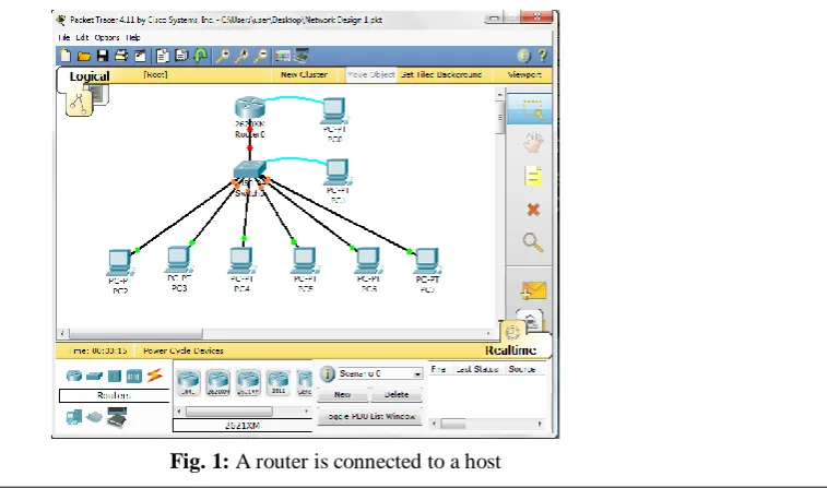
The Cisco network design in the simulation cannot work without knowing which equipment to connect to other equipment, without knowing the cables to use and connect any set of devices together that is, whether to use straight through cable, crossover or a rolled cable, worst still, the devices are not being configured by not just a network administrator but a Cisco network administrator. Three network designs are made in this paper and the equipments used in the simulation include routers, switches, hosts (PCs) and cables.
In figure 1, the router is connected directly with a rolled cable to a host at the right-hand side and with straight-through cable to a switch below it. The host connected to the router is used for the configurations. The switch is also connected with a straight-through cable to a host at the right-hand side for configurations and with straight-through cable to different hosts (PCs) below it.
3.1 Security Effect and Network
The security devices in figure 2 are the router and the switches. All the terminals and the interfaces (ports) are administratively shut down by default until they are configured.
Fig. 2: Routers and switches
The switches in the figure 3 have multi-ports which give room for expansion of the network. In fact, the network design in figure 3 is the expansion of network design in figure 2. The interfaces and ports in the switches in the network design 3 are configured which also adds more security to the network.
Fig. 3: Router in the network design
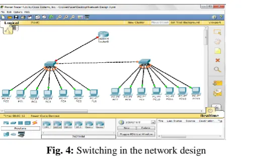
3.2 Switching and Network Design
The switches in the network design in figure 4 have multi-ports and breaks-up collision domain into separate and smaller collision domains. Collision domain is an internet term that describes a network collection of devices where a host transmits or sends a packet forcing every other host on that segment to pay attention to it.
IV. RESULTS AND DISCUSSIONS
We carry out an analysis of the performance of Cisco networks at saturation points of error-prone networks. The analysis was carried out using Packet Tracer Simulator to design network and OPNET Simulator to model the graph. These are industry's leading network development software. The results gotten will enable an enterprise network engineer to implement very high security networks free of inherent delays and capable of maximizing throughput. The proposed solution to the problems identified is implemented using OSPF routing protocol configurations.
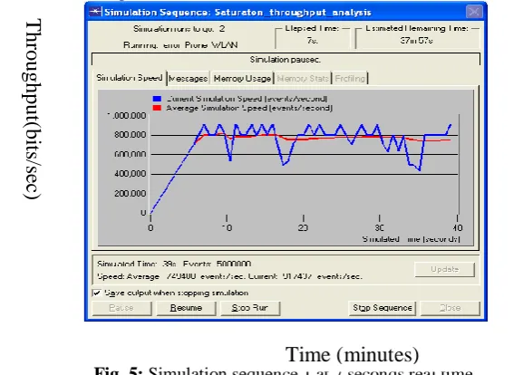
Figure 5 shows the simulation sequence at 7 seconds real time and 39 seconds simulated time.
Fig. 5: Simulation sequence 1 at 7 seconds real time.
The network was duplicated using a router to form two (2) separate broadcast domains – each domain having three stations, as shown in figure 5. Four statistics were chosen – delay, traffic received (packets/sec), traffic sent (packet/sec) and collision. Figure 5 shows the simulation runs captured at 39secs simulated time and 7 seconds real time. From the foregoing, it is seen that the maximum throughput gotten was 900,000 bits/sec and the minimum throughput gotten was about 420,000 bits/sec. This difference accounts for the effects of channel errors, collisions, path loss, thermal noise, interference.
Figure 6 shows the simulation sequence at 30 seconds real time.
Fig. 6: Simulation sequence 1 at 30 seconds real time
From figure 6, it is seen that as data transmission continued, the load on the network increases. More stations are involved in either sending packets or receiving packets which in turn also involved sending or receiving RTS and/or CTS signals, plus sending and receiving acknowledgments, carrier sensing to check if the
T
hr
oughput(
bi
ts
/s
ec
)
Time (minutes)
T
hr
oughput
(bit
s/s
ec
)
channel is idle or not, and backoff time. As seen in figure 6, the minimum throughput dropped below 400,000 bits/sec as against 420,000 bits/sec seen at the 39th sec of the simulation run. The graph in Figure 6 was captured at the 158th sec of simulation run (2 min, 38s). Observe also that the max throughput remains the same. Figure 7 shows simulation sequence at 60 seconds real time and 305 seconds simulated time.
Fig. 7: Simulation sequence 1 at 1 minute
At 305th sec of the transmission, the congestion status of the network is seen to be very high. The throughput at this saturation point is seen to be reduced more. Figure 8 shows the second half of the simulation runs at 5 seconds real time and 31 seconds simulated time.
Fig. 8: Simulation sequence 2 at 5 seconds
The figure 8 shows the beginning of the second half of the simulation runs. However, during the design phase, number of simulation runs was set at 2. At this phase, it is assumed that data transmission have started again after all stations backed off likely because the over-saturation of the network has caused slight link failure. Hence, at 31st sec, the max throughput is seen at around 700,000 bits per sec as against the original 900,000 bit/sec. This is true because the channel is still recovering from the failure.
T
hr
oughput
(
bit
s/s
ec
)
Time (minutes)
T
hr
oughput(
bi
ts
/s
ec
)
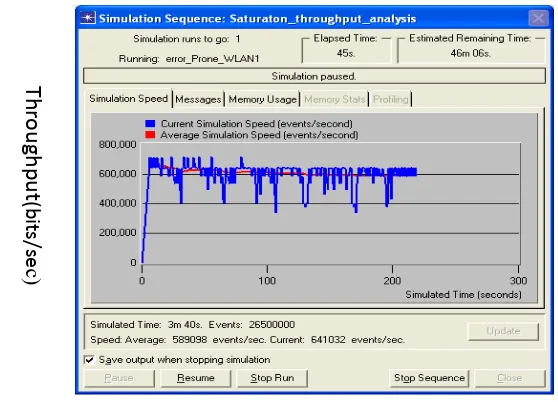
Figure 8 shows that as transmission continued to increase again, the minimum throughput declined more. Figure 9 shows simulation sequence two at 45 seconds real time.
Fig. 9: Simulation sequence 2 at 45 minutes
The results obtained show that under ideal conditions, throughput is maximized with large frames of data transmissions. However, IEEE 802.11 wireless networks are error-prone, and these errors reduce the saturation throughput performance at congestion points. From the foregoing, it can comfortably be stated that maintaining a reasonable amount of load on a collision domain can help a long way to maximize the throughput performance of networks.
V. CONCLUSION AND FUTURE WORKS
The convergence of multiple services into the data centre offers many operational benefits to the enterprise business. By converging computational, storage, application, and networking services, into one operational centre. This place stringent demands on the data centre design and the capabilities of the devices these services needed. In this paper, a detail analysis and design of Cisco network implementing routing, security, and switching was presented as an approach to congestion management. We design a Cisco network with routing and security using Cisco network simulator software (packet tracer), which ordinarily will not work without some set of configurations. We then show the configurations necessary for the routing and security. The model is validated through extensive simulation results. Our results show that routing, switching, and security were fully implemented in the model. The model is therefore recommended for any organization or computer networking firms that needs a standard, efficient, robust, and secure network.
In the future, we will expand the scope of this research work. This will involve the design and configuration of network that will always match the security standard that would be needed by any organization or computer networking firms at any time. Also, the future work should not only be to design and configure a Cisco network, but also to observe and point out where this Cisco network will not meet the networking standard again in security and efficiency.
REFERENCES
[1] D. Bertsekas and R. Gallager, Computer Networking with Internet Protocols and Technology, (Pearson Education, 1987).
[2] H. S. Chhaya and S. Gupta (1997). Performance Modeling of Asynchronous Data Transfer Methods of IEEE 802.11 MAC Protocol for Wireless Networks.
[3] H. Nguyen and G. Bianchi, Performance Analysis of the IEEE 802.11 DCF, Proc. of IEEE PIMRC, 1996, pp. 234-245.
[4] N. M. Rabadi and M. M. Syed, Performance Evaluation of IEEE 802.11a MAC Protocol for Vehicular Intersection Collision Avoidance System, 2002.
[5] IEEE 802.11 WG. International Standard for Information Technology – Local and Metropolitan Area Networks, Part 11: Wireless LAN MAC and PHY Specifications, 1999.
Th
ro
u
gh
p
u
t
(bi
ts/
se
c)
[6] B. Davide and P. Rong, Backward Congestion Notification version 2.1, IEEE 802.11 Meeting, 2005. [7] L. M. Feeney, B. Cetin and D. Hollos, Multirate Relay for Performance Improvement in IEEE 802.11
WLANs. Conf. Proc. of Universitat Paderborn, 2004, pp. 149-157.
[8] G. Bianchi. Performance Analysis of the IEEE 802.11 Distributed Coordination Function. IEEE Journal on Selected Areas in Communications, 2000.
[9] T. T. Blahut and E. Richard (2004). Algebraic Codes for Data Transmission (Cambridge University Press, 2004).
[10] P. Chatzimisios, A. C. Boucouvalas and V. Vitsas, IEEE Wireless LANs: Performance Analysis and Protocol Refinement, 2005.
[11] M. H. Manshaei, T. Turletti, Simulation Based Performance Analysis of 802.11a WLAN. Proceedings of IEEE, 2004, pp. 2-6.