FOSTER, RYAN DEAN. A Measurement of the Longitudinal Spin-Dependent Total Cross Section Difference, ∆σL, in the ~n−d~System. (Under the direction of David G. Haase and Christopher R. Gould.)
Three recent experiments in the nd system, each with a different observable, have produced results that do not agree with theoretical predictions. The discrepancies have typ-ically been ascribed to the poorly determined strength of the three-nucleon force. However, in the case of the recent high precision n-d scattering length measurement, the validity of some of the nucleon-nucleon force models has been questioned. To study these disagree-ments, we have initiated a program of measurements of the longitudinal spin-dependent total cross section difference, ∆σL, using a polarized neutron beam and a polarized deu-teron target for incident neutron energies of 1.18, 5.0, 6.88, and 9.0 MeV. Calculations have shown that ∆σL should be sensitive to the three-nucleon force.
We performed these measurements at Triangle Universities Nuclear Laboratory in Durham, NC. A polarized neutron beam was produced as a secondary beam from polarized proton or deuteron beams. The charged particle beams were created in the TUNL Atomic Beam Polarized Ion Source and were accelerated by a tandem Van de Graaff accelerator. The charged particle and neutron polarizations were determined from elastic scattering measurements.
DIFFERENCE, ∆σL, IN THE~n−d~SYSTEM
by
RYAN DEAN FOSTER
A dissertation submitted to the Graduate Faculty of North Carolina State University
in partial fulfillment of the requirements for the Degree of
Doctor of Philosophy
Department of Physics
Raleigh 2004
APPROVED BY:
Hugon Karwowski
Dean J. Lee Werner Tornow
1945–1997
Ryan Dean Foster
Personal
Born in Salisbury, NC, October 2, 1976
Married Amanda Jo Wagoner Rogers, May 26, 2001
Education
B.S. Physics, Western Carolina University, 1998 M.S. Physics, North Carolina State University, 2003
Thesis Title: A Measurement of the Longitudinal Spin-Dependent Total Cross Section Difference, ∆σL, in the ~n−d~System
Academic Positions
Teaching Assistant, NCSU, 1998–2001 Research Assistant, NCSU, 2001–2004
Memberships
American Physical Society
Contributed Abstracts
A Measurement of ∆σL in the~n−d~System. R.D. Foster, C.R. Gould, D.G. Haase, J.H. Kelley, D.M. Markoff, and W. Tornow. 17th International IUPAP Conference on Few Body Problems in Physics, Book of Abstracts, 267 (May 2003).
Upgrade and Testing of the TUNL Dynamically Polarized Deuteron Target. R.D. Foster, D.G. Haase, C.R. Gould, D.M. Markoff, J.O. Poole, and W. Tornow. Bulletin of the American Physical Society 46, 14 (2001).
An Upgrade of the TUNL Dynamically Polarized Deuteron Target. R.D. Foster, C.R. Gould, D.G. Haase, D.M. Markoff, J. Messimore, G. Palmquist, E. Pearson, J.O. Poole, and W. Tornow. Bulletin of the American Physical Society44, 11 (1999).
Co-Authored Abstracts
~n−d~ Scattering Measurements with the TUNL Dynamically Polarized Deuteron Target. D.M. Markoff, R.D. Foster, C.R. Gould, D.G. Haase, J.O. Poole, B.W. Raichle, and W. Tornow. Proceedings of the Ninth International Workshop on Polarized Sources and Targets, Nashville, Indiana (September 2001), 344. Wolrd Scientific, Singapore.
Oral Presentations
A Measurement of∆σLin the~n−d~System. R.D. Foster. Presented at the 15th National Nuclear Physics Summer School, Knoxville, TN (June 2003).
Writing these acknowledgements is something I have looked forward to for six years. For starters, it means I have finished my graduate studies and my dissertation, but most importantly, it gives me an opportunity to thank the people who have helped me get to this point. Without them, this dissertation would not have been possible.
I would first like to express my gratitude to Dr. David Haase for his guidance throughout my graduate studies. Despite being busy with the Science House, he was always willing to drop everything to help me and probably wishes that I had called him a little more than I did. He passed along not only his knowledge of physics, but also the professionalism that I hope to mimic in my career. Dr. Chris Gould shared his knowledge of nuclear physics and detectors and could always be counted on to find the silver lining in any situation. Dr. Werner Tornow could come into the control room and unfailingly find more beam hiding somewhere in the beam transport system. His assistance with the neutron polarimetry and the neutron production targets was also invaluable. I appreciate Dr. Dean Lee taking time out of his schedule to be on my committee and making the trip to Durham for my prelim and defense. I also want to thank Dr. Hugon Karwowski for agreeing to be a last minute addition to my committee.
This experiment could not have been performed without Drs. Diane Markoff and John Kelley. Dr. Markoff was an invaluable resource when I first joined the Polarized Target group. She guided me through the data acquisition software and electronics setup and could always be counted on to help set up for an experiment. Dr. Kelley graciously
proved to be an expert at tuning beam.
The excellent technical staff at TUNL also deserves recognition. John Dunham kept the ABPIS running and could be counted on to give me grief when the target wasn’t working. Richard O’Quinn and Paul Carter kept the accelerator in working order and Richard made sure I had liquid helium when I needed it. The Duke University Instrument Shop should be commended for its workmanship on the dilution refrigerator parts and various other projects that I brought to them. Bret Carlin and Sidney Edwards kept the data acquisition computers running and could be counted on to fix any problem I could throw at them. Pat Mulkey could find or build cables, rheostats, or anything else I was looking for.
Finally, I would not have been able to complete this degree without the love and support from my family. My parents provided the love and faith in me that are the foun-dation of my education. My mother has had to go it alone the last several years, but her support and strength have been unwavering. I only wish my father was here to share it with us. My brother Derek and his wife Jen have always been interested in how my research was going and I have truly enjoyed their friendship the last few years. My in-laws have accepted me into their family as one of their own and politely listened and nodded as I gave them a tour of the lab.
My wife Mandy has endured lonely nights at home, calls from the cryostat at 2 a.m., and has brought me supper at the lab too many times to count. I am not sure she knew what she was getting into when she married a graduate student pursuing a Ph. D. in experimental physics, but she has handled everything that has come her way with patience and understanding. She has brought so much love, laughter, and joy into my life and I couldn’t have accomplished this without her.
List of Figures x
List of Tables xii
Chapter 1 Introduction 1
Chapter 2 Theory 4
2.1 The Spin-Dependent Total Cross Section . . . 4
2.2 Polarized Neutron Beam Transmission . . . 7
2.3 Polarized Neutron Transmission Measurement . . . 9
2.3.1 Neutron Asymmetry Measurements . . . 9
2.3.2 Beam Polarization Measurements . . . 11
2.3.3 Deuteron Target Polarization Measurement . . . 13
Chapter 3 Polarized Neutron Beam 14 3.1 The TUNL Atomic Beam Polarized Ion Source . . . 14
3.2 Beam Acceleration and Transport . . . 18
3.3 Proton Polarimetry . . . 20
3.4 Neutron Production . . . 22
3.5 Neutron Polarimetry . . . 25
Chapter 4 Polarized Deuteron Target 27
4.1 Dynamic Nuclear Polarization . . . 28
4.1.1 Theory . . . 28
4.1.2 DNP Equipment . . . 33
4.2 Dilution Refrigerator . . . 34
4.2.1 Theory of Operation . . . 34
4.2.2 4He Cryostat . . . 36
4.2.3 Dilution Refrigerator Insert . . . 38
4.2.4 Target Insert . . . 39
4.2.5 Operating Procedures and Characteristics . . . 41
4.3 Thermometry . . . 42
4.4 Target Material . . . 44
4.4.1 Target Material Batch Comparisons . . . 44
4.4.2 Determination of Target Thickness . . . 44
4.5 Nuclear Magnetic Resonance . . . 46
4.5.1 Signal Acquisition . . . 47
4.5.2 Shape Fitting and Signal Analysis . . . 48
Chapter 5 Data Acquisition 52 5.1 Neutron Detectors and Electronics . . . 52
5.1.1 Zero Degree Main Detector . . . 52
5.1.2 Monitor Detector . . . 53
5.2 Data Acquisition Electronics . . . 54
Chapter 6 Data and Analysis 57 6.1 Beam Polarization . . . 57
6.1.1 Proton Beam Polarization . . . 57
6.1.2 Neutron Beam Polarization . . . 59
6.3 Neutron Asymmetries . . . 64 6.4 Calculation of ∆σL . . . 67
Chapter 7 Summary and Discussion 72
Appendix A Nucleon-Nucleon Potential Models 74
Appendix B The Two-Pion-Exchange Three-Nucleon Force 81
Appendix C Proton Polarimetry Test 85
Appendix D The program npinit.com 86
Appendix E The program go.com 92
Appendix F The program neutasym.for 95
2.1 ∆σL predictions for the CD-Bonn NN Potential with and without the TM
3NF.[Wit99] . . . 6
2.2 Schematic of the equipment used for the polarized neutron transmission ex-periment. . . 9
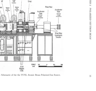
3.1 Schematic of the the TUNL Atomic Beam Polarized Ion Source. . . 15
3.2 Energy level splitting of the nuclear hyperfine states of hydrogen and deu-terium atoms in a magnetic field. . . 16
3.3 The TUNL low-energy beam transport facility. . . 18
3.4 The TUNL high-energy beam transport facility. . . 19
3.5 The polarimeter scattering chamber . . . 21
3.6 The deuterium gas cell neutron-production target. . . 23
3.7 The tritiated titanium neutron-production target. . . 24
3.8 The neutron polarimetry setup . . . 26
4.1 Spin-temperature theory of dynamic nuclear polarization . . . 31
4.2 Experimental ESR spectrum. . . 33
4.3 A simple dilution refrigerator. . . 35
4.4 The 4He cryostat. . . 37
4.5 The target insert and dilution refrigerator insert . . . 40
4.7 The TUNL polarized deuteron target NMR system. . . 47
4.8 Energy-level splitting of a deuteron in a magnetic field. . . 49
4.9 A plot of a typical NMR signal. . . 51
5.1 Online histograms of main and monitor detectors and BCI counts . . . 56
6.1 Energy spectra for 2.52 MeV protons elastically scattered from 4He . . . 58
6.2 Kzz0(0◦) data from [Wal98] . . . . 59
6.3 Energy spectra for 6.88 MeV neutrons elastically scattered from 4He . . . . 60
6.4 Comparison of Kzz0(0◦) values. . . 62
6.5 Plot of neutron asymmetry vs. BCI asymmetry . . . 66
6.6 Plot of ∆σL vs. En . . . 69
6.7 Plot of ∆σL vs. En . . . 70
6.8 Plot of ∆σL vs. En . . . 71
B.1 The two-pion-exchange 3NF force with a ∆ isobar. . . 82
3.1 Energy-loss calculations through the deuterium gas cell . . . 23
3.2 Energy-loss calculations through the tritium foil . . . 24
4.1 Typical operating parameters for the dilution refrigerator. . . 42
4.2 Values used in the calculation of the target thickness for each experiment. . 45
6.1 Proton beam polarimetry data. . . 58
6.2 Neutron polarimetry data. . . 61
6.3 Longitudinal neutron beam polarization calculations. . . 61
6.4 Calculation of spin temperature. . . 63
6.5 Calculation of NMR calibration constant . . . 63
6.6 Calculation of average target polarizations for October experiment. . . 64
6.7 Summary of neutron asymmetry measurements. . . 64
6.8 Acceptable ranges for October 2003 data. . . 65
6.9 Neutron asymmetry data. . . 65
6.10 Calculation of (∆σL)C. . . 68
6.11 Calculation of ∆σL. . . 68
A.1 Summary of properties and predictions of NN interaction models . . . 80
B.1 The cutoff parameter Λ used in the given potential combinations. . . 84
Introduction
Many of the current nucleon-nucleon (NN) potential models describe neutron-proton and proton-proton scattering data with remarkable precision [Wit99]. However, when these potential models are used to calculate the binding energy of the triton, the predictions are 500-800 keV below the measured value of 8.48 MeV. Three-nucleon forces (3NF) correct the problem, but do not eliminate discrepancies in other 3 nucleon systems. For example, in N-d elastic scattering, the differential cross section minima are underpredicted by NN interactions starting at 60 MeV and extending to higher energies. Adding the 3NF fills up the minima, but does not eliminate the disagreement. This is known as the Sagara discrepancy [Wit98]. The analyzing power (Ay) calculated from NN potentials in neutron-deuteron scattering at low energies is also 25-30% too small. This is the so-called “Ay puzzle”. Reasonable changes in the NN interaction and the inclusion of current three nucleon forces do not rectify the situation1. Finally, in very precise measurements of the ndcoherent neutron scattering length [Bla03], it was found that almost all theories were in disagreement with the experiment. It is clear from these disagreements between theory and experiment that the three body system is not well understood and that the current 3NF does not always correct apparent deficiencies in NN interactions.
1However, new three body forces which have not yet been taken into account, such as the spin-orbit type,
may resolve the disagreement [Hub98].
The investigation of the longitudinal spin-dependent total cross section difference, ∆σL, was motivated by these discrepancies. ∆σL is the difference in the~n−d~total cross section for spins parallel and anti-parallel to each other, with both spins aligned with the beam momentum axis.
The purpose of the present measurement was twofold. First, to confirm if stan-dard NN interaction calculations were able to reproduce experimental values for ∆σL to an accuracy of order 10 to 20% , indicating no radical disagreements with the two-body calculations. And second, to see if a clear distinction could be made between calculations with and without 3NF effects. Theoretical calculations predict that the Tucson-Melbourne three-nucleon force ([Coo79] and [Coo81]) changes ∆σL by 5-10% [Wit99] from its value calculated using only NN interaction potentials. Early experiments at TUNL in 1998-1999 had indicated large discrepancies with all theories [Mar02] [Mar99], but were not considered definitive because of low polarization of the target and the lack of scattering measurement determinations of the target and beam polarizations.
To improve the reliability of the ∆σLmeasurements, a number of improvements were made to the experimental apparatus. The3He evaporation refrigerator used in 1998/99 was converted to a dilution refrigerator in order to achieve lower target temperatures and higher target polarizations. The NMR system, which is used to measure target polarization, was improved in order to increase the signal to noise ratio and modified to measure directly the deuteron NMR signal and polarization. The target material used was fully deuterated 1,2-propanediol D8 as opposed to partially deuterated D6, providing a higher deuteron concentration and target thickness. Finally, ∆σL was measured relative to a low energy value based on the average of a set of calculations made with and without 3NF effects.
was compared to theoretical predictions.
Theory
This chapter provides the theoretical framework for the determination of ∆σL, con-centrating mainly on scattering theory and the theory of the measurement. An in-depth discussion of the meson-exchange nucleon-nucleon (NN) potential models, their properties, and their predictions of the triton binding energy is found in Appendix A. The two-pion exchange three-nucleon force and its effect on the triton binding energy are discussed in detail in Appendix B. Section 2.1 of this chapter examines the spin-dependent total cross section. Section 2.2 describes the transmission of a polarized neutron beam through a pol-arized target and contains the derivation of ∆σL. This chapter concludes with the theory of the measurements that were required for the determination of ∆σL. Section 2.3.1 con-tains the discussion of the neutron transmission asymmetry measurements and Section 2.3.2 describes the beam polarization measurements. Finally, the measurement of the deuteron target polarization is found in Section 2.3.3.
2.1
The Spin-Dependent Total Cross Section
Experimental data have shown that the nucleon-nucleon (NN) interaction has a tensor component [Wal98]. The existence of the tensor part of the NN interaction means that the nuclear potential contains non-central terms, so the spins of the particles must
be included when deriving the total cross section. The orbital angular momentum ` is no longer conserved when both particles have spin. The conserved quantity for the interaction between two particles with spin is J~, the total angular momentum, which is given by
~
J =~`+Ia~ +I~A=~`+~s (2.1) whereI~a(A) is the projectile (target) spin and~s is the channel spin.
The optical theorem relates the total cross sectionσT to the forward elastic scatter-ing amplitudefm0M0,mM(θ= 0) by
σT = 4πλIm X mm0M M0
ρmm0ρM M0fm0M0,mM(0◦) (2.2)
whereλis the reduced wavelength,ρmm0 andρM M0 are the density matrices of the projectile
and target nuclei [Hni94] and the primes represent the final states. The polarization states of the beam and target can be described by statistical tensors calculated in the “spin-axis” coordinate system rather than density matrices [Sat83] and the total cross section is (following the derivation in [Kei94])
σT = X
kK
σkK˜tK0(IA)˜tk0(Ia) (2.3) where
σkK = 2π k2Re{
X J X ``0 X ss0 X q
2J+ 1 (2Ia+ 1)(2IA+ 1)
Fq(J`s`0s0)
×[δ``0δss0−S`s`J 0s0]CKq∗ (βA, φA)Ckq(βa, φa)} (2.4) are the partial-wave cross sections summed over the initial and final states. The C(β, φ) terms are geometric terms specifying the orientation of the spin axes andβ and φ are the polar and azimuthal angles of the spin axis, respectively. The scattering amplitudesFq are
Fq(J`s`0s0) = X
Λ
(−1)K(−1)(J−s0)Λ ˆˆIaIˆA`ˆ`ˆ0sˆˆs0ˆkhΛk0q|Kqi
×h`0`00|Λ0iW(s0s``0,ΛJ)
Ia s IA Ia s0 I
A
k Λ K
where the terms in angular brackets are Clebsch-Gordon coefficients, W(s0s``0,ΛJ) is a
Racah angular momentum coupling coefficient, ~Λ is the angular momentum transfer, ~Λ = ~
`0−~`, and the expression in curly brackets is a 9-j symbol.
The longitudinal spin-dependent total cross section difference ∆σL is defined as the difference between the anti-parallel and the parallel total cross sections for spins aligned along the beam momentum axis:
∆σL=σa−σp. (2.6)
Calculations of ∆σL with and without the 3NF (Appendix B) are shown in Figure 2.1 for the CD-Bonn potential [Wit99].
0.0 1.0 2.0 3.0 4.0 5.0 6.0 7.0 8.0 9.0 10.0 11.0 12.0 13.0 Neutron Energy (MeV)
−2500.0 −2300.0 −2100.0 −1900.0 −1700.0 −1500.0 −1300.0 −1100.0 −900.0 −700.0 −500.0 −300.0 −100.0
∆σ
L
(millibarns)
CD Bonn CD Bonn + 3NF
2.2
Polarized Neutron Beam Transmission
While pd scattering can be measured to high precision, the most popular system for exploring the three-body interaction is ndscattering, since it is free of electromagnetic effects. This section derives the transmission asymmetry for a beam of polarized neutrons transmitted through a polarized target.
The intensity of a beam of 100% polarized neutrons passing through a target con-taining polarized nuclei is exponentially attenuated according to
Φ = Φ0e−xσp(a) (2.7)
where x is the target thickness in nuclei/barn and σp(a) are the cross sections for neutron and target polarizations parallel and anti-parallel, respectively. In terms of ∆σL,
σp =σ0− 1
2∆σL (2.8)
and
σa=σ0+ 1
2∆σL (2.9)
whereσ0 is the unpolarized total cross section. If the beam is not 100% polarized, then the transmission is a weighted sum of spin “p” and spin “a” neutrons, giving
Φ = Φ+0[e−Nd+xσpe−N −
dxσae−Nd0xσ0] + Φ−
0[e−N
+ dxσae−N
−
dxσpe−Nd0xσ0] (2.10)
where Φ±0 are the fraction of incident neutrons with spin up or down and Nd± and N0
d are the fraction of deuterons in the +1, -1, or 0 magnetic substates. These are given by Nd±= 1
2(1±PT −N 0
d) (2.11)
wherePT is the target polarization defined by PT =
Nd+−Nd−
Nd++Nd−+Nd0 (2.12)
and
Φ±0 = 1
wherePn is the neutron beam polarization defined as Pn=
Φ+0 −Φ−0
Φ+0 + Φ−0 . (2.14)
Substituting the expressions for Φ±0, Nd±, and σa(p) into Equation 2.10 we get for the transmitted neutron flux
Φ = 1
2(1 +Pn) h
e−12(1+PT)x(σ0− 1
2∆σL)e− 1
2(1−PT)x(σ0+ 1 2∆σL)
i +1
2(1−Pn) h
e−12(1+PT)x(σ0+ 1
2∆σL)e− 1
2(1−PT)x(σ0− 1 2∆σL)
i
. (2.15) We are interested in measuring the neutron transmission asymmetry due to reversing the neutron polarization, i.e.
²= Φ(Pn)−Φ(−Pn) Φ(Pn) + Φ(−Pn)
. (2.16)
The experimental conditions are such that if the positive and negative beam polarizations are equal
² = Pn
h
e12PTx∆σL−e− 1
2PTx∆σL
i e12PTx∆σL+e−
1
2PTx∆σL
(2.17) = Pntanh
· 1
2PTx∆σL ¸
(2.18) ≈ 1
2PnPTx∆σL. (2.19)
The last step is made because the argument is so small the the rest of the terms in the expansion can be safely ignored. If Pn+ and P−
n are not equal, then Equation 2.19 is still valid if Pn is the averageneutron beam polarization [Rai97]
Pn= 1 2(|P
+
n|+|Pn−|). (2.20)
The observable that is being tested in the ~n −d~ system for 3NF effects is the longitudinal spin-dependent total cross section difference, ∆σL. Solving Equation 2.19 for ∆σL we obtain
∆σL= 2² PnPTx
Figure 2.2: Schematic of the equipment used for the polarized neutron transmission exper-iment.
2.3
Polarized Neutron Transmission Measurement
The longitudinal spin-dependent total cross section difference is extracted from the spin-dependent neutron transmission asymmetries and measurement of the neutron beam and target polarizations and target thickness. The following sections describe the mea-surements that are required for the determination of ∆σL, including how we accounted for systematic variations from the ideal case described in Section 2.2.
2.3.1 Neutron Asymmetry Measurements
The “ideal” asymmetry excludes any systematic variations from neutron beam pro-duction, charged particle beam current, or charged particle beam polarization. This section will describe how these effects are accounted for in the monitoring of the experiment and analysis of the data.
As shown in Figure 2.2, the polarized neutrons are produced, pass through the polarized target, and are detected at 0◦. The actual opening angle is±1.27◦ about 0◦. Two
for normalization of incident neutron flux for the 2H(d, ~n)~ 3He reaction and to remove any systematic asymmetries due to the beam.
The measured neutron transmission asymmetry is
²Φ =²I+²n+²Pzz (2.22)
where ²I is the beam current asymmetry, ²n is the true spin-dependent asymmetry, and ²Pzz is an asymmetry dependent on the deuteron beam tensor polarization. See [Rai97]
and [Wal98] for derivations of these beam-dependent asymmetries. Because the monitor detector is upstream from the target, the neutron beam has not interacted with the target and the monitor detector measures an asymmetry
²Φ0 =²I +²Pzz (2.23)
where the prime denotes a monitor detector asymmetry. By subtracting the monitor asym-metry from the transmission asymasym-metry, the beam-dependent terms cancel out and the true asymmetry ²n is left.
Instrumental asymmetries can be removed by reversing the target polarization. Con-sider the neutron transmission asymmetry for positive target polarization
²n=
N+−N−
N++N−
(2.24) whereN± are the number of neutron counts in the main detector with polarization parallel
(+, positive polarization) or antiparallel (-, negative polarization) to the target polariza-tion. Now, if the target polarization is flipped, the neutrons that were parallel to target polarization are now anti-parallel and vice-versa. Therefore, ²n changes sign because the target polarization reversal does not affect the incident beam in any way. The average transmission asymmetry is
¯ ²n= 1
2(² +
n −²−n) (2.25)
where ²±
2.3.2 Beam Polarization Measurements
To calculate ∆σL, the polarization of the neutron beam must be determined. For the3H(~p, ~n)3He reaction, the neutron beam polarization was calculated from the measured polarization of the proton beam. For the 2H(d, ~n)~ 3He reaction, the neutron polarization was measured directly to avoid having to determine the tensor polarization of the deuteron beam.
Proton Beam Polarimetry
For the 1.18 MeV measurement, the 3H(~p, ~n)3He neutron production reaction was used. To determine the neutron beam polarization, the proton beam polarization was measured using the scattering chamber that is described in Chapter 3. The scattered protons from the 4He (~p, p)4He reaction produced a left-right scattering asymmetry. The measurement of the proton beam polarization and the subsequent calculation of the neutron beam polarization are described below.
A charged-particle polarimeter was used for proton polarimetry. A left and a right detector measured spin-up and spin-down protons. The four measured quantities wereNL+, NL−, NR+, and NR− which are the spin-up(+) and spin-down(-) counts in the left(L) and right(R) detectors, respectively. A scattering asymmetry γ is calculated
γ = N + LNR−
NL−NR+ (2.26)
where N is the total number of counts for a run of 256 8-step spin-flip sequences. The proton beam polarization is calculated from the asymmetry using
Pp= 1 Ay
√γ−1
√γ+ 1 (2.27)
the distribution of the measurements and is given by
σPp =
σ √
N (2.28)
where N is the number of measurements.
The resulting neutron beam polarization is calculated using known polarization transfer coefficients ([Jar74] and [Wal98]), which depend on incident beam polarization and energy. The neutron beam polarization is calculated from
Pn=PpKz
0
z (0◦) (2.29)
whereKzz0(0◦) is the longitudinal polarization transfer coefficient for the 3H(~p, ~n)3He reac-tion at 0◦. The uncertainty in the neutron polarization is
σPn =Pn s µ σPp Pp ¶2 + µσ
Kz0 z
Kz0
z ¶2
. (2.30)
Neutron Beam Polarimetry
For the 5, 6.88, and 9 MeV measurements, the neutron beam was produced through the2H(d, ~n)~ 3He reaction. The incident deuteron beam has vector and tensor polarizations and the neutron beam polarization depends on both according to the following relation:
Pn= 3 2PzKz
0
z (0◦) 1 +12PzzAzz(0◦)
(2.31) wherePz is the deuteron beam vector polarization, Kz
0
z (0◦) is the longitudinal pol-arization transfer coefficient for the 2H(d, ~n)~ 3He reaction, Pzz is the deuteron beam tensor polarization, and Azz(0◦) is the analyzing power for the reaction. Pzz is defined as
Pzz = h 3I2
z −I(I+ 1)i
I(2I−I) (2.32)
tensor polarization. However, excessive heating due to the large beam current proved to be problematic. Walston [Wal98] determined the tensor polarization by measuring the neutron yields in the monitor detector for longitudinal and transverse beam polarizations. These measurements were not as precise as Raichle’s. To overcome these difficulties, we decided to measure the neutron polarization directly.
Neutrons incident on a high-pressure cell of4He exhibit a left-right scattering asym-metry similar to the4He (~p,p)4He reaction. A pair of left-right detectors count spin-up and spin-down neutrons that are produced by the 2H(d, ~n)~ 3He reaction and scattered from a cell containing 1200 PSIG4He gas. The neutron beam polarization was calculated from the scattering asymmetry in the same manner as the proton beam polarization was calculated.
2.3.3 Deuteron Target Polarization Measurement
The deuteron target polarization was monitored regularly via nuclear magnetic reso-nance (NMR). The theory and equipment used for NMR will be detailed in Chapter 4. The deuteron target used in this experiment was polarized to approximately 25%. The NMR data consist of sets of signals, one or two per neutron data run, which were analyzed indi-vidually offline. Backgrounds were saved before polarizing the target and were subtracted in order to view the polarized deuteron signal. Each signal file name was recorded along with the neutron data run number and the target temperature.
Polarized Neutron Beam
The polarized neutrons are produced as a secondary beam from the 3H(~p, ~n)3He reaction for neutron energies less than 5 MeV and the 2H(d, ~n)~ 3He reaction for the higher energies. The polarized proton and deuteron beams are produced by the Atomic Beam Polarized Ion Source and the axis of polarization is set by the Wien filter. The beam is accelerated by a Van de Graaff accelerator, passes through an analyzing magnet, and is steered to the production target.
3.1
The TUNL Atomic Beam Polarized Ion Source
The TUNL Atomic Beam Polarized Ion Source (ABPIS) [Cle95a] can produce beams of vector polarized protons and vector and tensor polarized deuterons. A schematic of the ABPIS is shown in Figure 3.1.
3.
POLARIZED
NEUTR
ON
BEAM
15
E
B
HydrogenE
B
Deuterium +1 0 -1 -1 0 +1 1 2 3 4 5 6 +1/2 -1/2 -1/2 +1/2 1 2 3 4 state state}
}
+1/2 -1/2}
-1/2}
+1/2 mSmI mI mS
Figure 3.2: Energy level splitting of the nuclear hyperfine states of hydrogen and deuterium atoms in a magnetic field.
The source takes molecular hydrogen or deuterium and dissociates it in an rf dis-charge. The discharge is created by driving an rf coil at 14 MHz. This coil is wrapped around a quartz tube, which contains the gas to be dissociated. Nitrogen gas is also fed into the dissociator in order to reduce recombination of H or D. The atomic beam is slowed as it passes through a cryogenically cooled nozzle. The nozzle is cooled to 35 K by a 10 W closed-cycle Gifford-McMahan refrigerator.
The slow moving atomic beam is focused using two iron-core electromagnetic sex-tupoles. The sextupoles focus atoms that have electron spin parallel (ms = +1/2) to the magnetic field and defocus atoms that have spin anti-parallel (ms = −1/2) to the field. These defocused atoms are pumped away by four turbo pumps which have a combined pumping speed of 8800 l/s.
Three radio frequency transition units, one strong field (SF) unit and two medium field (MF1, MF2) units, are used to transfer the electron polarization to the nuclei. A magnetic field inside the units is used to produce the hyperfine splitting and an rf oscillator is tuned to a hyperfine transition frequency. The nuclei are polarized by interchanging populations of selected hyperfine states.
as it passes through the first sextupole. Because the first transition unit, MF1, is not used, the beam passes through the second sextupole unchanged. The SF unit is tuned to induce the 2→ 4 transition if positive or “spin-up” polarization is desired and as a result, states 1 and 4 are populated, with mI = +1/2. However, if negative, or “spin down” polarization is needed, MF2 is used to drive the 1→ 3 transition, leaving states 2 and 3 populated and mI =−1/2.
The polarized deuteron beam is produced in a similar way. As the atomic deuterium beam passes through the first sextupole, states 1, 2, and 3 are focused while 4, 5, and 6 are defocused and pumped away (see Figure 3.2). The MF1 transition unit is used in this instance and drives the 3→4 transition. The second sextupole then defocuses state 4. To produce positive polarization, SF induces the 2→6 transition, leaving states 1 and 6 populated and mI = +1. For negative polarization, MF2 drives the 1→4 and 2→3 transitions and states 3 and 4 are left populated and mI =−1. The beam polarization is longitudinal or parallel to the beam momentum.
After the polarized proton or deuteron beam leaves the transition units and sex-tupoles, it enters the electron cyclotron resonance (ECR) ionizer where it is stripped of its electron. The ECR contains an electron plasma that is produced by irradiating nitrogen gas with an rf field. The electron plasma removes the atomic electron via atom-electron collisions.
The TUNL electrostatic accelerator requires negatively charged beam so a cesium oven directly follows the ECR and is used to produce a negative beam by adding two electrons to the polarized nuclei. A vapor is formed in the oven by heating a sample of cesium to 200◦ C. Electrons are transferred from the vapor to the beam with a 10% efficiency as it passes through the oven. The ECR-cesium oven combination is used because positively- or negatively-charged beams can be produced with the same system, depending on whether or not the cesium vapor is present [Cle95b].
Inflection
Magnet Tandem
Accelerator Polarized
Ion Source
Wien Filter
Electrostatic Quadrupole
Steerer
Einzel Lens
Gridded Lens
Figure 3.3: The TUNL low-energy beam transport facility.
polarization axis to any direction. The magnetic field precesses the spin axis and the electric field keeps the beam on axis. The Wien filter is physically rotated to produce the necessary polarization axis orientation. The Wien filter is also used to compensate for precession through analyzing magnets. The negatively charged nuclear polarized beam is accelerated to the source frame voltage (-75 keV) and is focused with a set of lenses.
3.2
Beam Acceleration and Transport
The low energy transport facility connects the ABPIS to the electrostatic accelerator and is shown in Figure 3.3. A 30◦ bending magnet bends the beam towards the accelerator
where it is focused by two electrostatic quadrupoles and an Einzel lens and two magnetic steerers are tuned to control the beam position.
the tank is created by resistors located between the metal spacers. The terminal voltage is gradually stepped down to ground at each end of the column by a total resistance of 100 gigaohms. The accelerator uses a pelletron system, which consists of a pair of charging chains with one on each end of the tank, to deposit positive charge on the terminal. Each chain consists of stainless steel links separated by nylon spacers, is charged by a high-voltage supply at the tank wall, and deposits its charge on brushes in the terminal.
Steerer Feedback Tandem
Accelerator
Analyzing Magnet
Corona Feedback
Cryostat Leg Bending Magnet
Magnetic Quadrupole Magnetic Steerer Beam Current Slits
Neutron Production Target Beam Profile Monitor Charged Particle
Polarimeter Capacitive
Pick-Off
Figure 3.4: The TUNL high-energy beam transport facility.
beam, which is accelerated away from the terminal. This produces a beam with an energy that is roughly twice the terminal potential.
The beam leaves the high energy end of the accelerator and is analyzed in energy by a bending magnet (Figure 3.4). The field of this magnet sets the beam energy and is controlled by an NMR feedback system. Two slits downstream from the magnet provide a feedback signal to the terminal voltage stabilizer circuit. The terminal potential is set to minimize the current difference between these two slits. The control signal from the slits is fed back to the corona control tube by the Terminal Voltage Stabilizer circuit. The corona is a set of sharp needles that protrude from the tank wall towards the terminal and regulates the terminal voltage by drawing current from the terminal. The slit feedback signal controls a reverse voltage that is applied to the needles in order to make fine adjustments to the terminal potential. Further down the beamline, three magnetic steerers with feedback slits guide the beam to the neutron production target.
3.3
Proton Polarimetry
The neutron polarization of the beam produced by the 3H(~p, ~n)3He reaction was determined by measuring the polarization of the polarized proton beam via its transverse scattering asymmetry from 4He gas. A scattering chamber (Figure 3.5) several meters upstream from the polarized target was used for proton polarimetry. The chamber contained a 4He gas cell that could be moved in and out of the beam. The cylindrical cell had a 2.54 µm thick Havar foil wall that was epoxied to the cell frame contained one atmosphere of4He gas. Transversely polarized incident protons scattered from the 4He showed an up/down scattering asymmetry. Scattered protons were detected by two 1000 µm depletion depth silicon detectors positioned on separate support rings and biased to +97 V. The detectors could be placed in three degree increments from 45◦ to 135◦. Collimators were placed in
Beamline
QF-10 attachment to
gas manifold
Detector
Support Arms
Detector Holder
of 2.52 MeV at the center of the4He gas cell. The detectors were placed at an angle of 75◦,
which resulted in an analyzing power of 0.721±0.007. The analyzing power was calculated with the Fortran code Ay [Rai97], which is based on the explicit partial-wave expansion of the elastic scattering amplitude for spin 1/2 particles found in [Sat83]. Phase shifts were obtained from the effective-range parametrization from [Sch71]. A 2% systematic error from Schwandt’s measurements have not been included in this work because of the small effect it has on the final values of ∆σL. Asymmetry measurements were also made with the beam polarized longitudinally to check for a transverse component of the polarization and to verify the Wien filter settings. Data from the proton polarimetry measurements can be found in Section 6.1.
The signals from the polarimeter detectors pass through Ortec 142A preamplifiers and Ortec 572 amplifiers before being sent to Ortec 551 timing SCA’s. The signals are summed and then go to a Northern ADC. The SCA’s generate gates that append detec-tor routing information to the signals. Spin-routing bits are also added through an ADC interface. The extra routing information allows the use of one ADC for both detectors.
3.4
Neutron Production
The polarized neutron beam is created as a secondary beam from polarized protons or deuterons. For beam energies 5 MeV and greater, the 2H(d, ~n)~ 3He reaction was used to produce the neutron beam. The Q value for this reaction was 3.269 MeV. A gas cell, shown in Figure 3.6, containing 45 PSIA of deuterium gas was placed on the end of the beam line. The volume containing the deuterium was 6 cm long and 1.9 cm in diameter, producing a deuterium thickness of 4 mg/cm2.
Deuterium
Deuterium fill tube Havar
foil Ceramic
insulator
Steerer Slits
Vacuum attachment to beam-line
Tantalum beam stop
Deuterium
Figure 3.6: The deuterium gas cell neutron-production target.
energy is the difference in energy between neutrons produced at the start and end of the deuterium added in quadrature to the deuteron beam energy straggling through the Havar, estimated to be 10% of the energy loss through the Havar. Each neutron is not involved in the same number of collisions and as a result, does not have the same energy loss. The energy spread of the beam is a statistical distribution centered around some mean energy. This is known as straggling.
Table 3.1: Energy-loss calculations through the deuterium gas cell. Energies are in MeV. Beam Location Ed En Ed En Ed En
Havar Entrance 3.01 − 4.46 − 6.42 −
Havar Exit 2.43 − 4.01 − 6.07 −
D2 Entrance 2.43 5.69 4.01 7.27 6.07 9.27 D2 Center 1.78 5.00 3.60 6.88 5.79 9.00 D2 Exit 0.820 3.92 3.15 6.41 5.49 8.71
¯
En(∆En) 5.00 (1.77) 6.88 (0.86) 9.00 (0.56)
vacuum
TiT
2on foil
Havar foil
Ceramic insulator
Beam−line attachment
Steerer slits
to mechanical pump
Figure 3.7: The tritiated titanium neutron-production target.
For the 1.18 MeV data, neutrons were produced via the3H(~p, ~n)3He reaction, which has a Q-value of -0.764 MeV. A tritiated titanium (T iT2) foil of thickness of 0.11 mg/cm2 was placed at the end of the charged particle beam line and cooled by a flow of compressed air (Figure 3.7). The foil was isolated from the beam line by a 2.228 µm thick Havar foil and a 3.0 cm long evacuated buffer space. The energy of the produced neutrons is affected by the energy loss and spread in the Havar andT iT2 foils. As shown in Table 3.2, the final energy as calculated from the center of the T iT2 foil was 1.18 MeV with a spread of 0.07 MeV. A neutron count rate in the main detector of 250/s was achieved with 270 nA of 1.98 MeV protons.
Table 3.2: Energy-loss calculations through the tritium foil. Energies are in MeV. Beam Location Ep En
Havar Entrance 2.18 −
Havar Exit 2.01 −
TiT1.4 Entrance 2.01 1.21 TiT1.4 Center 1.98 1.18 TiT1.4 Exit 1.94 1.14
¯
3.5
Neutron Polarimetry
In the 2H(d, ~n)~ 3He reaction, the tensor component of the deuteron beam has a significant effect on the outgoing neutron polarization. Because the tensor component is so difficult to measure reliably, the neutron polarization was measured directly for the experiments with En≥5 MeV.
For the neutron polarimetry the deuteron beam was steered down the 38◦beam line
and into the neutron time of flight room. A neutron production gas cell similar to the one used for the neutron transmission experiment was filled with 45 PSIG of deuterium gas. The neutron polarimeter consisted of a 4He cell and neutron detector pairs arranged sym-metrically about the beam axis. A scattering asymmetry is measured in the detector pairs, enabling a very accurate calculation of the neutron beam polarization since the analyzing power of elastically scattered neutrons from 4He can be done with an accuracy of±0.01.
4
He cell
Neutron production
cell
Collimator
Neutron detectors
Detector support ring
Figure 3.8: The neutron polarimetry setup. This view is from above the equipment. The scintillation neutron detectors can be placed at arbitrary angles on the support ring. A left-right scattering asymmetry is measured and used to calculate the neutron polarization.
Polarized Deuteron Target
The deuteron target is polarized using the method of dynamic nuclear polarization (DNP). This method preferentially populates a certain magnetic substate by irradiating the target with microwaves tuned to the frequency of the substate splitting in a magnetic field. DNP allows for a relatively quick reversal of target polarization by retuning the microwave frequency. Because DNP requires that the target be at a low temperature and in a high magnetic field, the target is cooled to 250 mK using a 3He-4He dilution refrigerator, as described in Section 4.2. Thermometry is described in Section 4.3. The target material is discussed in Section 4.4. The target polarization is determined by nuclear magnetic resonance, which is described in Section 4.5. The chapter begins with an introduction to dynamic nuclear polarization.
A measurement of ∆σL can be characterized by a figure of merit which is propor-tional to the amount of experimental time required to achieve a certain precision in ∆σL. The figure of merit for a transmission experiment is proportional to (PTx)2 [Wal98]. In the present experiment, we have increasedPT by a factor of 2 to 2.5 over previous measurements [Mar02] by cooling the target with a dilution refrigerator. By choosing a fully deuterated (D8) target, the effective target thickness has been increased by one-third and the effects of extra protons have been significantly decreased.
4.1
Dynamic Nuclear Polarization
4.1.1 Theory
A polarized target can be thought of as an ensemble of nuclear and electronic spins placed in a large magnetic field and cooled to a low temperature. The interaction between the nuclear magnetic moment and the magnetic field produces 2I+1 Zeeman sublevels, where I is the nuclear spin. If the system is in thermal equilibrium, then the populations of the m sublevels for a spin I particle are given by a Boltzmann distribution,
nm=
e−∆kTE
P me−
∆E kT
(4.1) where ∆E=hνis the energy level splitting, h is Planck’s constant, k is Boltzmann’s constant, m is the magnetic substate, and T is the temperature of the system. The substate projections are defined by the magnetic field direction. The polarization of a spin-1/2 system is defined as
P(1/2) = N+−N− N++N−
(4.2) and the vector polarization of a spin-1 system is defined as
Pz(1) =
N+−N−
N++N−+N0
. (4.3)
A spin-1 system also has alignment as defined by Ad=
1−3N0 N++N0+N−
(4.4) and in thermal equilibrium the alignment is related to the vector polarization by
A2d−4Ad+ 3Pz2 = 0. (4.5)
Using these definitions, the thermal equilibrium polarizations can be described by P(1/2) =tanh
µ hν kT ¶ (4.6) and
Pz(1) = 4tanh( hν kT) 3 +tanh2(hν
kT)
At T=1 K and B=2.5 T, the spin 1/2 electrons are 92% polarized due to their large magnetic moment, which is 1838µN, where µN is the nuclear magneton. However, the deuteron’s magnetic moment is 0.857µN and under these conditions the deuterons have no useful thermal equilibrium polarization (0.05%). The technique of dynamic nuclear polarization provides a way to obtain high nuclear polarizations.
Dynamic nuclear polarization relies on the availability of “free” electrons, which, as discussed before, have a large thermal equilibrium polarization. These unpaired electrons are provided by doping the target material with a paramagnetic radical. The dipole-dipole coupling between the nuclear spins and the electron spins produces hyperfine splitting. By irradiating the target with RF waves tuned close to the electron spin resonance frequency, the polarization can be transmitted from the electrons to the nuclei. DNP works well because the relaxation time for electrons is very short compared to that of the nuclei.
If the spin-spin interaction between the electrons is ignored, then the process of DNP can be described by the solid-state effect [Abr61]. In this case, the electron spin resonance absorption line is narrow compared to the nuclear Larmor frequency. The Zeeman splittings are given by
∆ =hνS (4.8)
and
δ=hνI (4.9)
if the appropriate frequency microwaves are applied. A flip-flop is a forbidden transition because of quantum mechanical selection rules, but because of the dipolar interaction, the nuclear and electronic states are mixed and the flip-flop transitions are allowed to second order.
Consider a spin I that is down. It may do a flip-flop with a spin S that is up so that I is now up and S is down. Through its coupling to the lattice, S quickly relaxes and flips back up and may be used to flip another spin I. This way, each electron can be used to flip multiple nucleons because the number of polarizable nucleons is greater than the number of available electrons. The nucleon must have a long relaxation time in order for this process to be efficient. It is clear that if ν =νS+νI, then flip-flip transitions occur and all of the spins I end up down. The maximum nuclear polarization, PI, can be no greater than the electron polarization, PS.
When the concentration of electrons is large enough that the dipolar interactions among them cannot be ignored, the DNP process is described by the equal spin temperature theory [deB76]. When these interactions are considered, the Zeeman levels are no longer sharp, but are broadened. These levels can now be thought of as bands of semi-continous states, as in Figure 4.1(a). The populations of the states in these bands are given by Boltzmann distributions, with TZ the temperature of the electron Zeeman reservoir and TSS the temperature of the electron spin-spin interaction reservoir. The introduction of the spin-spin temperature is necessary because the dipolar interactions provide an additional energy reservoir that is independent of the Zeeman reservoir and the lattice temperature.
(a) (b) (c) n E n n E E hν hνL e −E kTS hν e −E kTZ hν e −E kTZ e −E kTSS e −E kTSS
Figure 4.1: The spin-temperature theory of dynamic nuclear polarization. (a) shows the distribution of spins n in thermal equilibrium with spin-temperature TS. (b) and (c) il-lustrate the separate electronic (TZ) and nuclear (TSS) spin-temperatures for positive and negative polarizations, respectively. The irradiation frequency is denoted by ν.
Zeeman temperature, TZn, are equalized.
The electron spin resonance response of the D8 propanediol target material was characterized by observing the absorption of microwave energy as a function of magnetic field. While the klystron frequency and power were held constant and the magnet current was swept stepwise, the resistance of a germanium thermometer located adjacent to the target material was observed. The resistance of the thermometer is proportional to the log of its temperature; as the temperature decreases the resistance increases.
The microwave heat input ( ˙QIN) is absorbed through non-resonant mechanisms in the thermometer and target cavity ( ˙QN R) and resonantly in the propanediol ( ˙QD8) [Ade96]. The realationship between the absorbed heat and the thermometer temperature is shown in the following equation:
˙
QIN = Q˙N R+ ˙QD8
= c(Tge4 −THe4 ) + ˙QD8
= cTge4 −cTHe4 + ˙QD8 (4.10)
wherecis a constant,Tgeis the temperature of the thermometer, andTHeis the temperature of the liquid helium in the mixing chamber. The heat from all processes is finally transferred to the helium bath through surface conduction. Therefore, as the propanediol absorbs microwaves the heat input to the thermometer decreases and the thermometer resistance increases. Figure 4.2 displays the raw data of germanium thermometer resistance versus successive sweeps of the current of the superconducting magnet. The minima near 78.2 A and 78.8 A mark the edges of the resonant absorption.
77.5 78.0 78.5 79.0 79.5 80.0 4
6 8 10 12
R
Ge(k
Ω
)
Magnet Current (A)
Figure 4.2: Experimental ESR spectrum. The magnetic field was swept up or down in 0.1 A increments and the resistance of the germanium thermometer was recorded at each step. Larger resistance values correspond to lower temperatures.
4.1.2 DNP Equipment
The magnet used in this experiment is a 10.16 cm bore split-coil superconducting magnet, oriented to provide a longitudinal field. The magnet is wound with Ni-Ti wire and is operated in persistent mode with 80 amps of current. Persistent mode provides a rated field homogeneity that is better than 0.01% over a volume of 1 cm3.
microwave frequency can be tuned so that positive and negative deuteron polarizations can be achieved near 69.3 and 69.7 GHz, respectively. These frequencies can be determined from the ESR absorption. The klystron settings for positive and negative polarizations were recorded as settings on a micrometer that was used for tuning. The frequency is fine tuned using the reflector voltage control on the power supply and a beat frequency between the microwaves and a reference frequency (11.5 GHz, the 6th harmonic of the 69 GHz microwave frequency) is observed on a frequency meter. Beat frequencies in the ranges 100-140 and 500-550 MHz were observed for positive and negative polarizations, respectively.
The klystron is connected to the target material via a 0.635 cm diameter cylindrical waveguide. The waveguide terminates in a microwave horn that is directly above the target material. An attenuator between the klystron and the waveguide allowed a fine adjustment of the delivered microwave power. The attenuator was adjusted so that the mixing chamber stayed below 350 mK.
4.2
Dilution Refrigerator
4.2.1 Theory of Operation
Liquid mixtures of3He and 4He undergo a phase separation when the temperature is lowered below 0.8 K. Below this temperature, a concentrated phase of pure 3He floats on a dilute phase that is 94% 4He and 6%3He. This phase separation remains in equilibrium down to absolute zero and is necessary for dilutive cooling [Lou79]. In a dilution refrigerator (Figure 4.3), the phase separation occurs in the mixing chamber. A tube extends from the dilute phase in the mixing chamber to the still so that an unbroken column of the dilute phase fills the still.
Mixing Chamber
Concentrated Phase
Dilute Phase
Heat Exchanger
Still
3
He Out
3
He In
between the mixing chamber and the still that is created by their difference in temperature. 3He atoms from the dilute phase in the mixing chamber travel up to the still because of the potential gradient. 3He atoms cross the phase separation from the concentrated phase to the dilute phase and cooling occurs. The 3He is recirculated and passes through a liquid nitrogen trap before re-entering the refrigerator. The incoming3He gas is condensed and is cooled by a heat exchanger before it enters the mixing chamber.
The dilution refrigerator used in this experiment is based on a PSI design [vdB90] and consists of three main components: the 4He cryostat, the dilution refrigerator insert, and the target insert. This particular design is very modular, in that the dilution refrigerator is completely separate from the4He cryostat. The cryostat is cooled to 2 K by pumping on a bath of liquid4He and is described in Section 4.2.2. The dilution refrigerator condenser is in good thermal contact with the 2 K bath and condenses the returning3He. The dilution refrigerator cools the target to 250 mK. The refrigerator and target inserts fit inside the cryostat in a concentric manner and are described in Sections 4.2.3 and 4.2.4.
4.2.2 4He Cryostat
The cryostat is described extensively in [Rai97] and [Wal98] and will be briefly reviewed here. It consists of a vacuum jacket, a central 4.9 cm diameter stainless steel tube, the liquid helium dewar, and the 2.5 T split-coil superconducting magnet. The magnet is connected to the liquid helium space by two stainless steel bellows. The cryostat is shown in Figure 4.4.
Superconducting
Magnet
Target
Cup
Refrigerator Access
2 K Bath
Vacuum
Heat
Shields
He Pump
4
He Pumps
3
He Delivery
4
a programmed upper limit and the sensor sends a signal to the process meter to close the nitrogen solenoid. The process meter also controls the backpressure in the storage dewar.
The4He bath is cooled to 2 K by pumping through a needle valve that is immersed in the bath. By pumping away the vapor above this small amount of liquid, the entire bath is slowly cooled. The 2 K pump is an Alcatel 2033 mechanical pump with a pumping speed of 35m3/hr. The needle valve was adjusted to keep the inlet pressure to the pump at approximately 9.5 torr.
The central tube accepts the dilution refrigerator insert and acts as the3He pumping line. The upper half of the tube is surrounded by the 2 K bath and the heat exchange for the dilution refrigerator condenser takes place across this interface.
4.2.3 Dilution Refrigerator Insert
The dilution refrigerator insert consists of the condenser, flow impedance, a con-tinuous heat exchanger, and mixing chamber and is based on the refrigerator described in [vdB90]. The insert has a 2.54 cm diameter axial opening that is sealed with the target insert (described in the next section). The condenser provides 250 cm2 of surface area that is in good thermal contact with the 2 K bath through a close-tolerance slip fit. The condenser is constructed of two concentric stainless-steel cylinders that have been welded to flanges at the top and bottom of the cylinders. A flow impedance after the condenser ensures that the3He pressure is high enough for condensation. The flow impedance is a 65” long piece of 0.004” inner diameter copper-nickel tubing. The impedance of the tubing was determined by flowing 6 PSIG 4He gas into the impedance and measuring the volumetric flow rate by collecting the gas in an upside down graduated cylinder that was submerged in water [Ric88]. The measured flow rate for 20 PSIG of 4He gas was 3.5×10⁻³cm3/s, which indicates an impedance of 4×1011cm−3.
thickness. Teflon tubing was used because its Kapitza resistance is four to six times smaller than that for copper-nickel or brass, which means that for the same amount of area, the heat exchanged will be four to six times larger for a Teflon exchanger [Fro92]. The heat exchange between two different media is inversely proportional to the Kapitza resistance, which depends on the nature of the media in contact. The Kapitza resistance for the 3 He-Teflon interface is almost an order of magnitude smaller than for 3He-CuNi or 3He-brass at 200 mK. A 4’6” length of the tubing was wrapped around a 3/32” diameter rod and heated for 10 minutes with a heat gun while being pressurized with 10 PSI nitrogen gas. The tubing was left on the rod overnight and was carefully transferred to the groove on the dilution refrigerator bobbin. The bobbin is made of Vespel SP22 and it has a spiral groove around it that is 0.16” wide and 0.16” deep. The heat exchanger rests in this groove and carries the 3He down to a piece of copper-nickel tubing that delivers the liquid to the mixing chamber. The impedance of the flow impedance and the heat exchanger in series was found to be 11×1011cm−3.
The mixing chamber is a 0.812” x 0.812” copper box with no bottom. The liquid drips through the mixing chamber and into the bottom of the stainless steel tube surround-ing the refrigerator insert. Because the target insert has sealed the axial space inside the refrigerator bobbin, the liquid flows up around the outside of the Vespel. The dilute phase that is flowing up the outside of the bobbin cools the incoming3He inside the Teflon tubing. The dilute phase rises to the level of the still which is heated to remain at 0.8 - 0.95 K. The still is a 4.24 cm tall stainless steel cylinder with 12 equally spaced holes drilled through its surface. The liquid passes through these holes into the central volume of the refrigerator, which is the pumping line. The vapor is pumped away by a 600 m3/hr and a 300 m3/hr roots blowers in series, backed by a hermetically sealed Alcatel 2063H mechanical pump.
4.2.4 Target Insert
free polarizable hydrogens. The inner dimensions of the holder are 1.4 x 1.4 x 1.4 cm. The NMR coil is wrapped around the target holder and is held in place by grooves cut into the outside of the holder. Two grooves cut into the Vespel plug fit around alignment pins in the refrigerator and set the position of the target holder. The plug is used to separate the mixing chamber and the still, creating two distinct volumes. An excellent seal is created by a 5◦ conical step. The microwave guide tube goes through the center of the plug and
terminates in the microwave horn directly above the target holder and material. Several copper heat shields are soldered along the central support tube and are cooled by the cold gas being pumped out. The dilution refrigerator and target insert are shown in Figure 4.5.
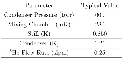
4.2.5 Operating Procedures and Characteristics
Table 4.1: Typical operating parameters for the dilution refrigerator. Parameter Typical Value
Condenser Pressure (torr) 600 Mixing Chamber (mK) 280
Still (K) 0.850
Condenser (K) 1.21
3He Flow Rate (slpm) 0.25
The 3He flow rate was measured using a Hastings model HFM mass flowmeter. Typical operating parameters are listed in Table 4.1.
4.3
Thermometry
Temperatures of various parts of the cryostat and refrigerator are measured with resistance thermometers. Ruthenium oxide resistors are used to measure the temperatures of the still and the dilute phase leaving the mixing chamber. Because the RuO near the mixing chamber has a high magnetoresistance and is not in the path of the microwaves, it can be used even when polarizing the target. A commercially calibrated germanium resistor (see Figure 4.6) is situated above the target cup and is immersed in liquid in the mixing chamber. This thermometer was used to calibrate the RuO with no microwaves and no magnetic field.
4.0 6.0 8.0 10.0 Ln(R)
0.0 0.2 0.4 0.6 0.8 1.0
T(K)
4.4
Target Material
The target material is fully deuterated 1,2-propanediol (D8) which has been doped with EHBA/CrV complex to provide free electrons for DNP. The dopant concentration for the samples used for taking neutron data was 5.1×10²¹ spins/ml. Other samples were prepared with 4×10¹⁹ spins/ml and will be discussed in Section 4.4.1. The material is prepared according to the recipe in [Kru79] and the procedure in [Cov02]. This preparation provides a high concentration of polarizable deuterons. The target material is frozen in 1 mm diameter beads and the beads are stored under liquid nitrogen. The target thickness was determined after each experiment by melting and weighing the target material.
4.4.1 Target Material Batch Comparisons
A batch of target material was made in July 2003 with a dopant concentration of 4×10¹⁹ spins/ml for the purpose of comparison to batches made with a higher dopant concentration. It was found that it was more difficult to tune the microwave frequency to get sizable target polarization and different klystron settings were tested in order to get a better microwave tune. However, no settings were found that reproduced the high polarization values from the target material with the higher spin concentrations. The polarizations with this target material were found to be 85% of the maximum achieved with the 1021spins/ml samples.
4.4.2 Determination of Target Thickness
propanediol, were weighed again and subtracted from the first measurement. The volume of the sample was calculated using measurements of the target cup and was found to be 2.729±0.006 cm3and the length in the beam direction was measured to be 1.405±0.003 cm. The fraction of the dopant in the material (mdopant/mtotal) and the fraction of propanediol (mD8/mtotal) were determined by the chemical composition of the material (0.0356 g EHBA-CrV per 1 gram of propanediol). The propandiol contained eight deuterons per molecule and Avagadro’s number of molecules per mole. The molecular weight of propanediol is 84.16 g.
The target area was calculated by dividing the target volume by the beam length and was found to be (1.942±0.006)×1024 barns. Dividing the total number of deuterons by the area in barns gives the target thickness. Table 4.2 contains the data for the target thickness calculations for the October and December experiments.
Table 4.2: Values used in the calculation of the target thickness for each experiment.
Parameter October December
Total target weight (g) 2.0200±0.0001 1.9434±0.0001
Fraction of propanediol 0.965 0.965
Mass of propanediol (g) 1.950 1.875
Mass of EHBA/CrV (g) 0.0694 0.0668
Total number of deuterons 1.116×10²³ 1.073×10²³ Total number of protons 2.49×10²¹ 2.39×10²¹ Deuteron Target thickness (nuclei/barn) 0.0574±0.0010 0.0553±0.0010
Proton Target thickness (nuclei/barn) 0.00128±0.00010 0.00123±0.00010
transmission experiment using
(∆σL)d= 2¯² PnPdxd −
Ppxp Pdxd
(∆σL)p. (4.11)
The second term on the right-hand side of the equation is referred to as the “cor-rection term”, (∆σL)C.
4.5
Nuclear Magnetic Resonance
Target polarization is measured using Nuclear Magnetic Resonance (NMR). A ma-terial’s magnetic susceptibility determines its response to RF radiation [Cra97] and can be measured with NMR. When the spin system is irradiated by an RF field at the Larmor frequency, it either absorbs some energy or the RF induces the system to emit energy. The inductance of the NMR coil is modified by the presence of the target material and is given by
L=Lo[1 + 4πQχ(ω)] (4.12)
where Lo is the inductance of the empty NMR coil, Q is the filling factor, and χ is the complex magnetic susceptibilityχ(ω)=χ’(ω)-iχ”(ω), which is a function of the applied RF field. Polarization is proportional to the imaginary part of the susceptibility,χ” integrated over all frequencies,
P =K Z ∞
0
χ00(ω)dω (4.13)
where K is a constant that depends on the nucleus being polarized.
λ/2cable R
D Wavetek
Synthesizer
R C
NMR coil
rf amplifier
diode output
50Ω
Figure 4.7: The TUNL polarized deuteron target NMR system.
circuit and is made of UT85 cryogenic cable with PTFE insulator and a copper tube outer conductor. The circuit response is measured and displayed with Labview. The LRC circuit is tuned to 16.35 MHz, which is the Larmor frequency of deuterons in a 2.5 T magnetic field. The frequency is swept ±300 MHz around the resonant frequency.
4.5.1 Signal Acquisition
the base frequency, the 10 torr baratron, the temperature of the RuO, and the number of sweeps. A typical signal was averaged over 1300 sweeps. A third order polynomial fit was applied to the first and last 60 channels of the sweep in order to get a more accurate calculation of the online signal areas.
4.5.2 Shape Fitting and Signal Analysis
The Fortran program dnmrarea3 reads and removes the header from the data file, does a third order least-squares polynomial fit to the wings of the signal, subtracts the fit, and calculates the area of the signal. This area is called the off-line area. A new data file is created containing subtracted signal. Because of the deuteron’s small magnetic moment, its thermal equilibrium signal is hard to observe. Therefore, the deuteron polarization is determined from the signal asymmetry ratio. The lineshape is fitted according to the procedures in [Ham81] and [Spe87].
The energy splitting of a deuteron in a magnetic field is shown in Figure 4.8. The deuteron is a spin 1 nucleus and has three magnetic substates: m = -1, 0, and 1. If only the magnetic field is considered, then the level splitting due to the interaction of the deuteron’s magnetic moment, µD, with the field B is
∆ =µdB. (4.14)
However, the deuteron has an electric quadrupole moment that interacts with the electric field gradient in the solid and produces an additional splitting,
δ =eqQ(1−3cos2θ) (4.15)
whereeis the electronic charge,q is the electrical field gradient,Qis the quadrupole moment, andθ is the angle between the magnetic field and the electric field gradient. The populations of the three substatesp−,p0, andp+ determine the nuclear polarization. The
deuteron vector polarization is defined as
Figure 4.8: Energy-level splitting of a deuteron in a magnetic field.
assuming the populations are normalized by
p++p0+p−= 1. (4.17)
It is assumed that the deuteron system is in internal equilibrium and can be de-scribed by a spin temperature, Ts. This assumption has been proved to be accurate by [Bor71]. In this equilibrium case, the relative populations of the magnetic substates are given by the Boltzmann distribution,
r= p+ p0
= p0 p−
=ekTshν (4.18)
![Figure 2.1: ∆σL predictions for the CD-Bonn NN Potential with and without the TM3NF.[Wit99]](https://thumb-us.123doks.com/thumbv2/123dok_us/1564583.1192280/20.612.135.477.286.546/figure-sl-predictions-cd-bonn-nn-potential-wit.webp)