On Evaluating Fault Resilient Encoding Schemes
in Software
Jakub Breier1∗, Xiaolu Hou2∗and Yang Liu3 1Underwriters Laboratories, Singapore
2Acronis, Singapore
3School of Computer Science and Engineering Nanyang Technological University, Singapore
Email: [email protected], [email protected], [email protected]
F
Abstract—Cryptographic implementations are often vulnerable against physical attacks, fault injection analysis being among the most popular tech-niques. On par with development of attacks, the area of countermeasures is advancing rapidly, utilizing both hardware- and software-based approaches. When it comes to software encoding countermeasures for fault protection and their evaluation, there are very few proposals so far, mostly focusing on single operations rather than cipher as a whole.
In this paper we propose an evaluation framework that can be used for analyzing the effectivity of software encoding countermeasures against fault attacks. We first formalize the encoding schemes in software, helping us to define what properties are required when designing a fault protection. Based on these findings, we develop an evaluation metric that can be used universally to determine the robustness of a software encoding scheme against bit flip faults and instruction skips. We provide a way to select a code according to user criteria and also a dynamic code analysis method to estimate the level of protection of assembly implementations using encoding schemes. Finally, we verify our findings by implementing a block cipher PRESENT, protected by encoding scheme based on anticodes, and provide a detailed evaluation of this implementation using different codes.
Index Terms—fault injection attacks, encoding schemes, software imple-mentations, block ciphers, cryptography, coding theory
1 Introduction
Protection and physical attacks on cryptographic implementations are ever-evolving areas, resulting into continuous effort on each side to make advancements over the other one. Attackers utilize various techniques that can break the protection and reveal infor-mation about the data or secret key. On the other hand, data owners and custodians try to prevent these attacks by applying wide range of countermeasures.
There are various ways to analyze a device and its implemen-tation, Fault Analysis (FA) being one of the most popular ones. Since the first reported attacks, protecting the implementations of ciphers have become a major concern. When selecting a countermeasure, one needs to decide what degree of protection to implement, taking into account the data value and protection price. There is no universal countermeasure, each method has its
∗This research was done while the authors were with Nanyang Technological
University, Singapore
advantages and limitations. In general, countermeasures can be classified into hardware-based and software-based.
Implementers currently still rely more on hardware-based approaches, such as shielding [1], sensors [1], or hardware re-dundancy [2]. This is mostly because to inject a fault, physical methods are normally used, such as lasers, electromagnetic pulses, or voltage/clock glitches [3], and therefore, physical protections are effective in detecting/thwarting these.
There are works that utilize encoding techniques in hardware to provide fault resiliency, e.g. [4], [5], [6]. However, there is no straightforward way to implement such schemes in software and therefore, these papers do not provide any details on potential efficiency and security in case the countermeasure is ported into software.
Our Contribution
In this work we are interested in analyzing software encoding countermeasures for a full cipher implementation. To facilitate the evaluation, we formalize fault models and encoding countermea-sures in software, bringing light into understanding of what is needed and what is possible.
We formalize evaluation metrics that measure the robustness of a code against bit flip faults and instruction skips on a full cipher implementation. We present the exact formula of our metric for a code used in protecting one single operation. Such an analysis gives us insights on what kind of codes to choose – we show that both theminimumandmaximumdistances of a code are important. This leads us to the notion ofanticodefrom coding theory which is a definition of code that bounds both minimum and maximum distances of a binary code.
We provide theoretical analysis for what parameters an anti-code exists, which gives a direct overview of feasibility without the need to manually search for the anticode existence. As the next step, we present an algorithm to automatically select anticodes with required properties for protecting cryptographic implementa-tions against DFA (if such codes exist).
2 used our evaluation method to analyze the performance of different
anticodes w.r.t. aforementioned metric. Our results reveal what trade-offs between the security level and the efficiency (speed, time) can be achieved. Both advantages and disadvantages are discussed. To the best of our knowledge, this is the first work im-plementing and evaluating the software encoding countermeasure on a full cipher.
The rest of the paper is organized as follows. Section 2 discusses related works. Section 3 formalizes fault attacks and encoding countermeasures in software. In Section 4 we present our metric for evaluating a code used in encoding countermeasure with respect to bit flip faults and instruction skips. The exact formula for our metric in case the code is used for protecting one operation is provided in Section 5 along with the notion of anticodes. Algorithms used for code selection and for evaluation of software implementations are detailed in Section 6. Section 7 provides a case study on block cipher PRESENT. Section 8 gives a guideline on how to choose anticode parameters. Discussion is stated in Section 9 and finally, Section 10 concludes this paper and provides a motivation for future work.
2 RelatedWork
2.1 Differential Fault Analysis
When it comes to analyzing symmetric block ciphers under fault conditions, the most effective and popular method is the Differential Fault Analysis (DFA) [7]. Following this method, the attacker normally disturbs the computation circuit during the last three rounds of the encryption and then she compares the faulted ciphertext with the non-faulty one. By analyzing this pair of ciphertexts, she can get the information about the secret key used in the encryption. In some cases, single pair is enough to reduce the key search space to a feasible number [8], [9]. In other cases, several fault injections are necessary [10], [11].
2.2 Countermeasures
Software countermeasures against fault attacks can be generally divided into two main groups: instruction-level and algorithm-level techniques [12]. Instruction-based countermeasures include instruction duplication or triplication, and fault-tolerant instruction sequences, where an instruction is replaced by functionally equiv-alent sequence of more secure instructions [13]. This technique was recently extended to a new approach, calledintra-instruction redundancy [14]. In this technique, data is split among several instructions, by using a redundant bit-slicing.
On the other hand, algorithm-level countermeasures include temporal and information redundancy on an algorithm level [15]. Temporal redundancy techniques normally execute the algorithm several times and then compare the results for inconsistencies [3], [16].
Software encoding countermeasures fall in the second cate-gory, introducing the redundancy in the information being pro-cessed. Depending on the encoding scheme design and amount of redundancy, these countermeasures can provide a robust alter-native to hardware-based approaches [17]. Breier and Hou [18] showed how to select codes with desired fault properties for protecting binary operations. Theoretical bounds of software en-coding countermeasure used in a whole cipher implementation are considered in [19], [20]. However, no real implementation or simulation was given in either work. Servant et al. [20] considered
a particular code when used in a full cipher, which they referred to as (3,6)-code, that is actually a (6,16,2)−binary code (see Definition 3). The probability of detecting a fault was analyzed in this case and it is 93.75%. The approach in [19] does not consider some important aspects of fault injection, such as ability of the attacker to precisely select the fault mask or his ability to inject instruction skips. Generally, to avoid a successful fault injection attack for the countermeasure in [19], used code would have to remain a secret.
2.3 Countermeasure Evaluation Methods
Moro et al. [21] developed an evaluation platform based on electromagnetic fault injection to experimentally verify temporal redundancy countermeasures at assembly instruction level. They implemented a protected version of FreeRTOS to conduct the study. Two countermeasures were tested – an instruction skip protection and a fault detection that is applicable to a subset of assembly instructions. Their experiments showed that both countermeasures work in a way they are supposed to, however with obvious limitations that come from their designs – they either protect only against instruction skips and not against other, more complex fault models, or they can only protect several chosen instructions of the code.
Yuce et al. [12] provided experimental evaluation of several instruction level countermeasures by using a single clock glitches. They showed that the most popular choices, such as instruction du-plication/triplication, parity, and instruction skip countermeasure can be broken by a careful choice of fault scenario.
Goubet et al. [22] aimed at formal verification of countermea-sures by using automata and SMT solver. Such approach required a decomposition of a code into pieces, while analyzing each piece separately. Also, the method works by comparing the unprotected code with the protected one. The proposed method, however, is not scalable for a full cipher evaluation – for code snippets, where 10 lines of code need 10.7 s to evaluate. Furthermore, analyzing small snippets separately might not reveal the vulnerabilities that might arise from connecting them to a full implementation (cf. Remark 10).
Breveglieri et al. [6] evaluate a subset of encoding-based countermeasures for hardware, based on parity/residue check bits. However, such methods provide only a limited amount of security – odd number of bit-flips is detected, but even number always passes the checks. Moreover, the attacker can also disturb the parity bit or the “checkpoint” which provides the integrity check.
In case of encoding based software countermeasures, there are no works proposing a full cipher evaluation to the best of our knowledge. The closest works to this one evaluate only a single operation on encoded data [18], [17].
Our method is universal for encoding based software coun-termeasures and provides details on all the possible bit flips and instruction skips. Also, the dynamic code analysis technique that was implemented can efficiently evaluate a full cipher implemen-tation in a short time.
3 SoftwareEncodingSchemes
3.1 Fault Attacks in Software
Assembly language is a low-level programming language, specific to a particular architecture. Normally, there is a one-to-one map-ping between assembly instructions and machine code that is being executed on the device. Assembly language uses a mnemonic to represent machine operations in the form of instructions. Each instruction falls into one of three categories: data movement, arithmetic/logic, and control-flow.
Operands are entities operated upon by an instruction. Ad-dresses are the locations of specified data in the memory. Operands can be immediate (constant values), registers (values in the pro-cessor number registers), or memory (value stored in the memory). Standard instruction can have zero to three operands, the leftmost operand being usually the destination register, the second and the third are source registers.
For our purpose, registers are the most important storage units. Size of the register is typically stated in bits and depends on the device architecture (e.g. 8-bit, 32-bit, 64-bit). Normally, all the registers for a particular device have the same size. It is the fastest type of memory in a computer and it is directly accessible by the arithmetic logic unit (ALU) performing the operations.
Definition 1. We define aprogram to be an ordered sequence of assembly instructions F = {f1,f2, . . . ,fNF}. NF is called
the number of instructions for the program. For any assembly instruction f ∈ F, if f has a destination register, we denote this register by rf. LetS denote the set of all programs.
Fault attack is an intentional change of the original data value into a different value. This change can either happen in a register/memory, on the data path, or directly in ALU. In general, there are two main fault models to be considered – program flow disturbances and data flow disturbances. The first one is achieved by disturbing the instruction execution process that can result in changing or skipping the instruction currently being executed. The second one is achieved either by directly changing the data values in storage units, or by changing the data on the data paths or inside ALU. For the purpose of a fault injection attack, these three data flow changes are equivalent and can be modeled by changing the values in registers.
Definition 2(Instruction skip and fault mask). 1) For any i ∈
Z>0, an ith instruction skipis a functionϑi:S →S, such
thatϑi(F)=F if NF <i andϑi(F)=F \{fi}otherwise.
2) For any j ∈ FN
2\{0} (N ∈ Z>0), a fault mask j on
in-struction i is a function ςi,j : S → S such that for any
F ={f1,f2, . . . ,fNF} ∈S,
• if 1 ≤ i < NF and fi has a destination register rfi
whose length is at least N, then ςi,j(F) = {f1,f2, . . . ,
fi,f˜i,fi+1,fNF}, where f˜i = eor rfi j, i.e. f˜i changes the
value in rfi, to be thexored result of value in rfi and j.
• ςi,j(F)=F otherwise.
In our evaluation framework, we consider asingle fault adver-sary– under this attacker model, at most one fault is injected dur-ing the encryption/decryption algorithm execution. The attacker can inject a random m−bit flip fault such that all the bits have equal probability to be affected by the fault. In other words, for a randomm−bit flip, each fault mask value between 1 andNhas the same probability to occur.
3.2 Fault Resilient Encoding Scheme
Encoding scheme in our context is a protection method that acts against fault injection attack by detecting malicious changes to secret data processed by the encryption algorithm. In this part we provide a necessary formalization which establishes the foundation for Section 4, where a generic metric for evaluating encoding scheme robustness is proposed.
A binary code, which we denote byC, is a subset ofFn2, the
n−dimensional vector space overF2, wherenis called thelength
of the code C. Each element c ∈ C is called a codeword of C and each element x ∈ Fn
2 is called a word [23, p.6]. Take two
wordsx,y∈Fn2, theHamming distancebetweenxandy, denoted
by dis (x,y), is defined to be the number of places at which x andy differ [23, p.9]. More precisely, if x= x1x2. . .xn andy =
y1y2. . . yn, then
dis (x,y)=
n
X
i=1
dis (xi, yi),
wherexiandyiare treated as binary words of length 1 and hence
dis (xi, yi)=
1 ifxi,yi
0 ifxi=yi
.
Furthermore, for a word x ∈ Fn2, the Hamming weight of x,
wt(x) :=dis (x,0) [23, p.46]. For a binary codeC, the(minimum) distanceofC, denoted by dis (C), is [23, p.11]
dis (C)=min{dis c,c0
:c,c0∈ C,c,c0}.
Definition 3. [24, p.75] For a binary code C of length n, with dis (C)=d, if M=|C|is the number of codewords inC. ThenCis called an(n,M,d)−binary code.
Remark 1. In caseCis a subspace ofFn2,Cis called a linear code.
For a linear code with dimension k, a standard notion would be [n,k,d], where n is its length and d is its minimum distance. For a non-linear code, there is no notion of dimension and we follow the standard notion(n,M,d)as presented in [24]. We would like to emphasize that we do not restrict the code to linear codes, allowing the analysis to more code candidates used in encoding countermeasure.
To simplify the notation we introduce the symbol ⊥, which indicates an error. Note that the exact implementation of⊥gives certain restrictions on the codeCthat can be used: if zero is used to implement⊥, we should require that0<C.
To formally define encoding countermeasure, we first adopt the definition of symmetric cipher from [25]:
Definition 4. Asymmetric cipher(see e.g. [25, p.37]) is a5−tuple (K,P,M,E,D)such that
E:K × P → M, D:K × M → P,
and∀κ∈ K,∀P∈ P, D(κ,E(κ,P))=P. We refer toK ,P,M, E and D askey space,plaintext space,ciphertext space,encryption anddecryptionof this cipher, respectively. We defineSto be the set of all symmetric ciphers(K,P,M,E,D)such that
K =FN1
2 , P=F
N2
2 , M=F
N3
2 ,
for some N1,N2,N3∈Z>0.
4 Definition 5. Anerror detection symmetric cipheris a 5−tuple
(K,P,M,E,D), where 1) ⊥∈ M,
2) E:K × P → M,D:K × M → P ∪ {⊥}are functions such that∀κ∈ K,∀P∈ P
a) if D(κ,E(κ,P)),⊥then D(κ,E(κ,P))=P;
b) D(κ,⊥)=⊥.
Let S⊥ denote the set of all error detection symmetric ciphers (K,P,M,E,D)such that
K =FN1
2 , P=F
N2
2 , M=F
N3
2 ∪ {⊥},
for some N1,N2,N3∈Z>0.
In encoding countermeasure, the important part is the error detection, which is closely related to the encoding and decoding. Here we formalize the notion of encoder and decoder.
Definition 6. Given an (n,M = 2k,d)−binary code C, an encoding-decoding scheme associated withCis a pair of functions (EncoderC, DecoderC)
EncoderC:Fk2→ C, DecoderC:Fn2∪ {⊥} →F k 2∪ {⊥}
such that DecoderC
(
Fn2∪{⊥})\C =
{⊥} and EncoderC is bijective
withDecoderC
C being its inverse.
Thus for DecoderC an error message ⊥ will be returned if the input is not a codeword. More details regarding encoding-decoding schemes can be found in Appendix A.
Definition 7. Anoperationis a mapg:F2M1×F M2
2 × · · · ×F Mm
2 →
FM2m+1 for some positive integers M1,M2, . . . ,Mm+1. Let Sdenote
the set of all operations.
Note that an assembly implementation of an operation is a program (see Definition 1).
Example 1. The xor operation defined on 1-bit strings is an operationg:F2×F2→F2such that
g(0,0)=0, g(0,1)=1, g(1,0)=1, g(1,1)=0.
Definition 8. An operation with error detection is a map h : (FM21 ∪ {⊥})×(F
M2
2 ∪ {⊥})× · · · ×(F Mm
2 ∪ {⊥}) → F Mm+1
2 ∪ {⊥}
for some positive integers M1,M2, . . . ,Mm+1 such that if x =
(x1,x2, . . . ,xm) ∈(FM21∪ {⊥})×(F M2
2 ∪ {⊥})× · · · ×(F Mm 2 ∪ {⊥})
satisfiesxi=⊥for at least one i∈ {1,2, . . . ,m}, then h(x)=⊥. Let
S⊥denote the set of all operations with error detection.
Remark 2. By the above definition, for any symmetric cipher (K,P,M,E,D) ∈ S, E,D ∈ S. For any error detection sym-metric cipher (K,P,M,E,D) ∈ S⊥, D ∈ S⊥. Furthermore, for an(n,M = 2k,d)−binary codeC with associated
encoding-decoding scheme (EncoderC,DecoderC), EncoderC ∈ S and
DecoderC ∈ S⊥.
Example 2. Consider the following operation with error detection h: (F2∪ {⊥})×(F2∪ {⊥})→F2∪ {⊥}. h outputs thexorof two
bits when no error is detected:
h(0,0)=0, h(0,1)=1, h(0,⊥)=⊥,h(⊥,0)=⊥, h(⊥,⊥)=⊥,
h(1,0)=1, h(1,1)=0, h(1,⊥)=⊥ h(⊥,1)=⊥.
An operationg∈ Scan be changed to an operation with error detection utilizing binary codes:
Definition 9. Given an(n,M=2k,d)−binary codeC,ϕ
C :S → S⊥is defined as follows:
Take anyg:FM21×F M2
2 × · · · ×F Mm
2 →F
Mm+1
2 ∈ S, for1≤i≤m+1,
suppose{EncoderC(x)|x∈FM2i}=Cki ⊆
Fnk2i,ϕC(g)is a function:
ϕC(g) :Fnk21∪ {⊥}
×Fnk2
2 ∪ {⊥}
× · · · ×Fnkm 2 ∪ {⊥}
→ Ckm+1∪ {⊥}
such that forx=EncoderC(x1),EncoderC(x2), . . . ,EncoderC(xm)
∈ Ck1× Ck2×. . .Ckm,ϕC(g)(x)=Encoder
C
g(x1,x2, . . . ,xm)
, and
∀x∈Fnk1
2 ∪{⊥}
×Fnk2
2 ∪{⊥}
×· · ·×Fnkm
2 ∪{⊥}
\Ck1×Ck2×. . .Ckm,
ϕC(g)(x)=⊥.
Example 3. Let us take the functiongfrom Example 1 and take the following(2,2,2)−binary codeC={00,11}with the following encoding-decoding scheme:
EncoderC: 07→00, 17→11,
DecoderC: 007→0, 017→⊥, 107→⊥, 117→1.
ThenϕC(g) : (F22∪ {⊥})×(F22∪ {⊥})→ C is an operation with
error detection and
ϕC(g)(x1,x2)=
00 x1=x2=00or11
11 x1=00,x2=11orx1=11,x2=00
⊥ otherwise.
Lemma 1. Letg1, g2∈ Ssuch thatg2◦g1∈ S, thenϕC(g2◦g1)=
ϕC(g2)◦ϕC(g1).
(The proof can be found in Appendix B.1.)
Remark 3. For any symmetric cipher (K,P,M,E,D) ∈ S, any(n,M =2k,d)−binary code Cwith an associated
encoding-decoding scheme(EncoderC,DecoderC), if we write E=g1◦g2◦
· · · ◦gmforg1, g2, . . . , gm∈ S, thenϕC(E)=ϕC(g1)◦ϕC(g2)◦ · · · ◦
ϕC(gm).
This justifies that we can split or merge multiple cipher operations while considering applying encoding countermeasure to a symmetric cipher (cf. Section 7.1).
Encoding countermeasure applied to a symmetric cipher can be considered as applying a function which is closely related to a binary code on the encryption and decryption of the cipher. Here we give the definition of such a function.
Definition 10(Fault resilientC-map). Given an(n,M =2k,d)−
binary codeCwith an associated encoding-decoding scheme (EncoderC,DecoderC), we definefault resilientC-mapto be the following function
ΦC:S → S⊥
(K,P,M,E,D) 7→ (K,P,M ∪ {⊥},E0,D0),
such that∀P∈ P, κ∈ K,Msg∈ M\{⊥},
E0(κ,P)=DecoderC
ϕC(E)EncoderC(κ),EncoderC(P), D0(κ,Msg)=DecoderC
ϕC(D)EncoderC(κ),EncoderC(Msg), and D0(κ,⊥)=⊥.
Now we are ready to formalize encoding countermeasure, which we refer to asfault resilient encoding scheme.
Definition 11(Fault resilient encoding scheme). Given(K,P,M, E,D) ∈ S a symmetric cipher and C an(n,M = 2k,d)−binary
A cipher of the formΦC
(K,P,M,E,D)is called afault resilient encoding scheme.
Remark 4. Taking k = 1 and C = {01,10}, we get the bit-sliced encoding, e.g. the one used in [26] (EncoderC(0) = 01, and EncoderC(1) = 10) which follows the principle of a dual-rail precharge logic. In Section 7.1, we use k=4mainly because PRESENT cipher uses 4-bit SBox (see Section 7.1).
P
κ
EncoderC(P)
EncoderC(κ)
E ϕC(E)
EncoderC(P),EncoderC(κ)
Msg DecoderC
Msg
κ
EncoderC(M sg)
EncoderC(κ)
D ϕC(D)
EncoderC(M sg),EncoderC(κ)
P DecoderC
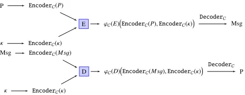
Fig. 1: Overview of the fault resilient encoding scheme.
For a better understanding of how the fault resilient encoding scheme works, the design overview is stated in Figure 1. Infor-mally, first, an encoder is applied to both the plaintext and the key. Then, the encryption process is performed, preserving the encoding. In the end, a decoder is applied in order to get the encrypted message. The decryption process is analogous.
4 EvaluationMetric
In this section we first formalize faults in encoding schemes and provide concepts of safe and missed faults. Then, we propose two metrics for evaluating different binary codes used for fault resilient encoding scheme: one for bit flip fault model and one for instruction skip fault model.
4.1 Faults in Fault Resilient Encoding Schemes
We first give the definition of safe and missed faults for an implementation of ϕC(g) (i.e. for a single operation), where C is a binary code andgis an operation.
Definition 12. Given an (n,M = 2k,d)−binary code C with
encoding-decoding scheme(EncoderC,DecoderC), an operation g ∈ S, letF be an assembly implementation of ϕC(g). Suppose F ={f1,f2, . . . ,fNF},
1) The set of possible instruction skipsforF is
G(F,sk):={ϑi: 1≤i≤NF}.
2) The set of possible fault masksforF is
G(F,fm):={ςi,j: 1≤i≤NF,j∈Fn2\{0},fi
has a destination register}. (1)
3) For an integer1≤m≤n,the set of possiblem−bit flipsfor F is
G(F,fm,m):={ςi,j:ςi,j∈ G(F,fm),wt(j)=m}.
4) A fault onF is defined to be a function%such that%∈ G(F,sk)
or%∈ G(F,fm).
5) Fixing an input x, a fault%onFis said to besafeif%F=⊥ org(x); and it is said to be amissedfault otherwise.
Remark 5. A fault is closely related to a tampering function defined in [27]. In our notation, a fault is defined on the program code level, but in a broader sense, the effect of introducing a fault in the program execution can be considered as an application of a tampering function.
Given an (n,M = 2k,d)−binary code C associated with an
encoding-decoding scheme (EncoderC,DecoderC) and a sym-metric cipher (K,P,M,E,D). Let (K,P,M ∪ {⊥},E0,D0) := ΦC
(K,P,M,E,D). The assembly implementations ofE0andD0 are programs. If we let F1 andF2 be the assembly implementa-tions ofE0 andD0 respectively, then for anyκ∈ K,P∈ P,Msg∈ M ∪ {⊥},F1(κ,P) = E0(κ,P) and F2(κ,Msg) = D0(κ,Msg). We
assume the registers involved in the implementation all have length at leastn. Recall that E,D ∈ S (Remark 2), we hence give the following definition of safe and missed faults for a fault resilient encoding scheme.
Definition 13(Safe and missed faults). For a fixed plaintext P∈ P and a keyκ ∈ K, a fault %1 on F1 issafe if%F1(κ,P) =⊥or E(κ,P)and it is called amissedfault otherwise. Similarly, a fault %2 on F2 issafeif %
F2
(κ,P) =⊥ or D(κ,P)and it is called a missedfault otherwise.
Recall that for a differential fault analysis [7], the attacker needs to inject a fault during the execution. Based on where the fault is introduced, diffusion can spread it up to the whole cipher state by the end of encryption. Attacker then compares the faulty output with the correct one and can gain information about the secret key. If the fault is missed, the attacker can use similar technique. In this case, the cipher output would be equivalent to the faulty output obtained by attacking an unprotected cipher implementation. On the other hand, if the fault issafe, it means the output is either⊥or the correct output, which will not give the attacker valuable information.
4.2 Metrics for Bit Flips and Instruction Skips
In this part we give the metrics we use to evaluate the fault resistance property of a binary code used in fault resilient encoding scheme. Since bit flips and instruction skips are quite different fault models in nature, we propose different metrics for each of them.
The metrics are defined for the implementation of encryption. Similar metrics can be defined for the implementation of decryp-tion.
As mentioned earlier, for anm−bit flip fault attack model, we assume all combinations of m bits have equal probability to be flipped. Thus,
Pr[ςwas injected]= 1 |G(F1,fm,m)|
, ∀ς∈ G(F1,fm,m).
Furthermore, given a particular fault%, the probability that%is safe is calculated assuming that the plaintext and key are independent random variables following uniform distribution1. More precisely,
Pr[%is safe]= |{p, κ:P∈ P, κ∈ K, %is safe for plaintextP, keyκ}|
|P||K | .
Definition 14(m−bit fault resistance probability). Following the notations from Definition 13. Let m be an integer such that
1. This meansPr[plaintext=P]= 1
6 1 ≤ m ≤ n, the m−bit fault resistance probability of C w.r.t.
(K,P,M,E,D)andF1, denoted by pC,m, is defined as
pC,m :=
X
ς∈G(F1,fm,m)
Pr[ςis safe]Pr[ςwas injected]
= 1
|G(F1,fm,m)|
X
ς∈G(F1,fm,m)
Pr[ςis safe].
We are interested in the best case for the attacker, i.e. we consider she can inject a fault that has the highest probability to be missed by the encoding scheme. Therefore, we have to take the minimum of them−bit fault resistance probabilities. To check the overall resistance of a code in fault resilient encoding scheme, we consider all the possible bit flips and definebit flip resistance probabilityas follows:
Definition 15 (bit flip fault resistance probability). Given an (n,M = 2k,d)−binary code C, a symmetric cipher (K,P,M,E,D), and an implementation F1 of E, the bit flip
fault resistance probabilityforCw.r.t. to(K,P,M,E,D)andF1,
denoted by pC,bf, is defined as:
pC,bf:= min
1≤m≤npC,m,
where pm,C is the the m−bit fault resistance probability ofCw.r.t. to(K,P,M,E,D)andF1.
The bit flip fault resistance probability will be used as our metric for evaluating a code used in fault resilient encoding scheme w.r.t. bit flip fault attacks.
For instruction skips, we give the following metric:
Definition 16 (instruction skip resistance probability). Given an (n,M = 2k,d)−binary code C, a symmetric cipher (K,P,M,E,D), and an implementationF1 of E, theinstruction
skip resistance probabilityforCw.r.t. to(K,P,M,E,D)andF1,
denoted by pC,sk, is defined as:
pC,sk :=
X
ϑ∈G(F1,sk)
Pr[ϑis safe]Pr[ϑwas injected]
= 1
|G(F1,sk)|
X
ϑ∈G(F1,sk)
Pr[ϑis safe].
Remark 6. We do not assume faults on input data, such as plaintext and key. In case the attacker wants to attack these, she could do it anytime before the actual algorithm execution, even before the encoding. Similarly, we do not assume faults on ciphertext – in this case, the attacker would not get any meaningful information about the secret key.
5 Anticodes forFaultResilientEncodingScheme
In this section, we first provide the exact formulas for pC,bf and
pC,sk in case of a simple “cipher” which consists of one binary
operation (Section 5.1). Binary operations are very common in symmetric ciphers, e.g.xor,and,modular addition.
We remark that analyzing the fault resistance property of a code C with respect to a single operation gives insights on the overall fault resistance of using C in fault resilient encoding scheme. Hence it provides a good approximation of the fault resistance of a full cipher implementation.
In Section 5.2 we introduce anticodes which give improved resistance probabilities compared to codes with unbounded dis-tances.
Finally, Section 5.3 provides a way to check the existence of an anticode for given parameters.
1 LDI r0 x //loading of plaintext 2 LDI r1 key //loading of key
3 EOR r2 r2 //pre-charge registerr2to zero 4 LPM r2 r0 r1 //execution ofgby table look up 5 ST y r2 //storing ciphertext
TABLE 1: Assembly implementationF forϕC(g), whereg:F2M1×
FM22→F M3
2 is a binary operation.
5.1 Evaluation of Single Operations
Letg∈ Sbe a binary operationg:F2M1×FM22→F2M3and letCbe
an (n,M=2k,d)−binary code with associated encoding-decoding
scheme (EncoderC,DecoderC) and distanced ≥2. We will use zero string to denote ⊥, the error message. Hence we further require that0<C. And we chooseksuch thatk=max{M1,M2}.
Remark 7. As mentioned in Remark 1, we do not restrict our codes to be linear. Thus the method of calculating syndrome [23, p.62] of a word and check if this word is a codeword does not apply in our setting. Furthermore, using table lookup for implementation and a null word for denoting error does not require an extra computation (e.g. calculating syndrome) to detect error.
LetF be the assembly implementation (in Figure 1) ofϕC(g). In F, two different instructions are used:LDI loads immediate data into the destination register,LPM loads data from a program memory to the destination register – serving as a table lookup for the binary operation g. Before executing each table look-up we precharge the destination register to zero by using exclusive or operation (EOR in line 3). Note that the table has 2n×2nentries. The value stored at address (a,b) is zero ifa,b<Cand the value isEncoderC(g(EncoderC(x),EncoderC(y))) ifa=EncoderC(x) andb=EncoderC(y).
By Definition 12 and the assumptions stated in Remark 6, the set of possible instruction skips and the set of possible fault masks forF are given by
G(F,sk)={ϑ3, ϑ4}, G(F,fm)={ςi,j:i=3,4,j∈Fn2\{0}}.
The values of pC,m andpC,sk with respect to the programF and
ϕC(g) can be then calculated as follows:
Proposition 1. 1. For 1 ≤ m ≤ n, let Sm,C := Pc∈C|{c0 ∈ C : dis (c0,c)=m}|, then2
pC,m=1−
Sm,C
2Mmn
. (2)
2. pC,sk=1.
(The proof can be found in Appendix B.2.)
Remark 8. If Sm,C=0, then pC,m=1. This is equivalent to saying
that in case there are no two codewords inCthat are at distance m from each other, m−bit flip fault model would not result in missed faults.
5.2 Fault Resilient Anticode Scheme
In this part, we explain the rationale behind extending the encod-ing scheme with a usage of anticodes to provide better bit flip resistance probabilities.
When selecting the code parameters, the choice of n is dependent on the architecture of the device and the memory constraint. The value ofMis mostly related to the cipher design (see Section 8).
For binary codes with the same length n and cardinality M, the formula from Proposition 1 shows that the smaller the value of Sm,C
(n m)
, the bigger pC,mcan be achieved. By Definition 15, to get
a code with higher bit flip fault resistance probability, we want to look at codes where the value ofSm,C
(n m)
is small.
Since Pn
m=1Sm,C = M(M−1) is always true, to make Sm,C (n
m)
small, one strategy is to makeSm,Csmall or even equal to zero for smaller values ofmn. Let
`:=
n
2 ifnis even n+1
2 ifnis odd
. (3)
It is known that (see e.g. [28, p.26])
n
i−1
<n
i
if 1≤i< `
n
i−1
>n
i
if` <i≤n, and
n
`−1
=n
`
ifnis odd
n
`−1
<n
`
ifnis even. (4)
Hence, we would like to haveSm,C=0 form“close to”nand we do not wantSm,C=0 for too manym(see Lemma 2).
In the view of the above, we recall the notion ofanticode:
Definition 17. [29] A binary anticode is an array of binary digits with n rows and M columns, constructed so that the maximum Hamming distance between any pair of rows is less than or equal to a certain valueδ. This valueδis themaximum distanceof the anticode.
If we have a binary code, we can take its codewords as rows and then get an anticode. Note that a binary code does not have repeated codewords but an anticode can have repeated rows [29]. The above discussion shows that essentially what we want is a binary code which is also an anticode with a proper maximum distanceδ. We introduce the following definition.
Definition 18. LetCbe an(n,M,d)−binary code and let
δ:= max
c,c0∈Cdis c,c
0,
thenCis called an(n,M,d, δ)−binary anticode (we can see that d ≤ δ ≤ n). Furthermore, d (resp. δ) is called the minimum distance(resp.maximum distance) ofC.
From the definition, it is clear that a binary code can always be considered as a binary anticode. The difference is that the notion of anticode captures the maximum distance of the code, which is closely related to the selection of codes with better bit flip fault resistance probability. Here, we rename our fault resilient encoding scheme below to emphasize the usage of anticode.
Remark 9. LetCbe an(n,M,d, δ)−binary anticode, by Proposi-tion 1, for m<d and m> δ, pC,m=0with respect toF andϕC(g)
in Section 5.1.
Definition 19 (Fault Resilient Anticode Scheme). Given (K,P,M,E,D) ∈ S a symmetric cipher and C an (n,M = 2k,d, δ)−binary anticode with an encoding-decoding scheme
(EncoderC,DecoderC). A cipher of the formΦC
(K,P,M,E,D) is called afault resilient anticode scheme.
To analyze the choice of C that is used in a fault resilient anticode scheme, we theoretically study the performance ofCwith
respect to F andϕC(g) in Section 5.1. Although the following theoretical analysis only analyzes a single operation of a cipher, we will see from the simulation results in Section 7.2 that it gives good insights on what anticode to choose for a full cipher implementation.
Next, we consider n,M as fixed parameters and we assume ` > 2 (Equation 3), hence we also assume n ≥ 6. For any (n,M,d, δ)−binary codeC, letpC,bf (resp.pC,m) denote its bit flip
fault resistance probability (resp.m−bit fault resistance probabil-ity) w.r.t.F andϕC(g) in Section 5.1.
We have the following observations.
Lemma 2(Advantage of anticodes for fault detection). 1. LetC1
be an(n,M,d1,n)−binary anticode, we have pC1,bf ≤1−
1 M.
2. LetC2be an(n,M,d2, δ2)−binary anticode such thatδ2−d2≤2,
we have pC2,bf≤1−
M−1 6(n
`).
3. LetC3be an(n,M,d3, δ3)−binary anticode,
a. if Sm,C1<2
n
m
∀1≤m≤n, then pC3,bf>pC1,bf;
b. if Sm,C3<
M(M−1)(n m) 3(n
`) ∀1≤m≤n, then pC3,bf>pC2,bf.
(The proof can be found in Appendix B.3.)
We remark that in 3-a, takingm=nimpliesSn,C3 =0, which
means in this case δ3 < n. This corresponds to our previous
observation thatSm,C = 0 form “close” ton may give anticode with better fault resilient property. Condition 3-b implies that there are at least 3 m such thatSm,C3 , 0, which corresponds to our
observation that it is not desirable to haveSm,C =0 for too many m.
5.3 The Possible Choices of Anticodes
The next natural question would be: for what kind of parameters n,M,d, δ, there actually exists an (n,M,d, δ)−binary anticode? We introduce the following notation.
N(n,d, δ) :=max{M:∃(n,M,d, δ)−binary anticode}. (5)
Two related well-studied coding theory concepts are [30, p.42]
A(n,d) :=max{M:∃(n,M,d)−binary code},
and [31]
B(n,d) :=max{M:∃(n,M,d)−binary codeC, s.t.∀c,c0∈ C,
dis c,c0=
0 ord}.
We have
Lemma 3. i N(n,d,d)=B(n,d); ii N(n,d,n)≤A(n,d);
iii N(n,d, δ)≤N(n+1,d, δ);
iv N(n,d, δ)≤N(n+1,d, δ+1), whereδ≥d+1; v N(n,d+1, δ)≤N(n,d, δ), whereδ >d+1;
vi N(n,2r−1,2`−1)≤N(n+1,2r,2`)where r, `∈Z>0;
vii N(n,2r−1,2`)≤N(n+1,2r,2`), where r, `∈Z>0;
(The proof can be found in Appendix B.4.)
In Section 7.1 we will study and analyze the implementation of a fault resilient anticode scheme with PRESENT cipher. Because of the cipher design we will be interested in anticodes with cardinality 16 (see Section 7.1).
8 TABLE 2: Possible values of d, δ such that there exists an
(n,16,d, δ)−binary anticodes forn=8,9,10.
n d δ
8 2 4,5,6,7,8
8 3 6,7,8
8 4 8
9 2 4,5,6,7,8,9
9 3 6,7,8,9
9 4 6,8,9
10 2 4,5,6,7,8,9,10
10 3 6,7,8,9,10
10 4 6,7,8,9,10
satisfying condition 3-a or 3-b in Lemma 2 is not guaranteed. However, by using our anticode selection algorithm (Section 6.1), we were able to find anticodes satisfying both conditions 3-a and 3-b in Lemma 2. As expected, they have high bit flip fault resistance probability when used in fault resilient anticode scheme (cf. Remark 10).
We would like to emphasize that searching for an anticode with Algorithm 1 is time-consuming, especially for codes with highn. Also, it might not be apparent whether an anticode exists until the whole code space is searched. Therefore, Lemma 3 helps in this direction – it tells us whether it makes sense to run Algorithm 1 for given parameters.
6 Algorithms
In this section, we provide two useful algorithms for practical evaluation of encoding schemes. The first one selects binary anticodes according to user requirements and the second one evaluates software implementations that follow the fault resilient anticode scheme.
6.1 Anticode Selection Algorithm
In order to use and analyze the fault resilient anticode scheme, we first need to select the binary anticodes. The algorithm created for this purpose is described in this section.
Similarly to previous section, we choose the anticodes based on their performance on a single cipher operation. This gives a good approximation of an overall resistance when it is used for a full cipher implementation.
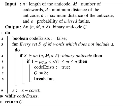
Pseudocode outlining the main idea of the anticode selection is stated in Algorithm 1. The inputs are: parametersn,M,d, δfor the binary anticode, and εsuch that we require that the selected binary anticodeCsatisfies 1−pC,m< εfor all 1≤m≤n, where
pC,m is them−bit fault resistance probability ofCwith respect to
F andϕC(g) in Section 5.1. Thus the calculation of pC,m follows
from Proposition 1.
We note that for our implementation we use zero word as ⊥ and thus in line 3 we choose setsS which do not contain0.
The algorithm takes each possible binary codeS that consists ofMcodewords, each of lengthn(line 3), and test if the distance conditions are satisfied (line 4). I.e. whether the following two conditions are satisfied: 1) min{dis (c,c0) : c,c0∈S,c
, c0}=d;
2) max{dis (c,c0) : c,c0 ∈ S,c
, c0} = δ. In case the distance
conditions are satisfied, we further check if the fault resistance probability ofS can be fulfilled (line 5).
Theεparameter is crucial for selecting an anticode with good fault resilient capabilities. As long as at least one anticode exists
Algorithm 1:Anticode Selection Algorithm. Input :n: length of the anticode,M: number of
codewords,d: minimum distance of the anticode,δ: maximum distance of the anticode, andε: probability ofmissedfaults.
Output:An (n,M,d, δ)−binary anticodeC. 1 do
2 booleancodeExists :=false;
3 forEvery set S of M words which does not include⊥ do
4 ifS is an(n,M,d, δ)−binary anticodethen 5 if1−pC,m< ε∀1≤m≤nthen
6 codeExists :=true;
7 C:=S; 8 break for;
9 ε:=ε−const; 10 whilecodeExists;
11 returnC.
for givenε, the algorithm will try to lower this value (line 9) by a pre-specified constant, to find binary anticodes which satisfy the conditions with even smallerε.
6.2 Dynamic Code Analysis
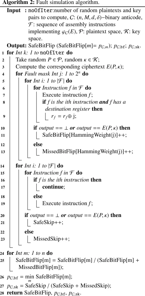
For the purpose of fault analysis, we have designed a dynamic code analyzer that is able to simulate the code execution and fault injection with a bit precision in any instruction of the code. Along with the bit flips, it can simulate instruction skips (see Definition 2). Pseudocode implementing the evaluation is stated in Algorithm 2.
For a symmetric cipher (K,P,M,E,D), and an (n,M,d, δ)−binary anticodeC, let (K,P,M ∪ {⊥},E0,D0) denote the corre-sponding fault resilient anticode scheme (Definition 19). GivenF, an implementation ofE0, Algorithm 2 calculates approximations of them−bit fault resistance probability pC,m (Definition 14), bit
flip fault resistance probability pC,bf (Definition 15) and
instruc-tion skip resistance probability pC,sk (Definition 16) of C with
respect to (K,P,M,E,D) andF.
By definition, the values of pC,m,pC,bf,pC,sk should be
calcu-lated by evaluating each pair of plaintext and secret key. However, for a symmetric cipher, this would require an infeasible amount of calculations. For PRESENT-80, it would need 2144evaluations of
each fault model (80-bit key and 64-bit plaintext). Thus, we allow a user inputnoOfIterwhich specifies how many pairs of random plaintext and random secret key to consider. Hence the output will be approximations of our evaluation metrics.
We first select a random pair of plaintext and secret key, then compute the corresponding correct ciphertext (line 3).
instruction number corresponds to the number that is currently being targeted, a bit-flip is performed (line 9). After the execution ofF finishes, there is a checking of the output value (lines 10-13). If the value equals to the expected ciphertext E(P, κ), or the value is ⊥, it is asafefault. Otherwise, it is amissed fault (see Definition 13). In each case we increment a corresponding value in the array, where the array index indicates the Hamming weight of the fault mask.
Lines 14-23 evaluate instruction skips. It works in the same fashion as the previous part, however, in this case we save one loop because we do not need a fault mask. Output evaluation is analogous, but the records of safe/missed faults will be integers instead of array of integers.
Lines 24-25 calculate the approximated values ofpC,mfor each
m, which is equal to the number of safem−bit flip faults divided by the total number ofm−bit flip faults considered. Line 26 calculates the approximated value ofpC,bf, which is the minimum ofpC,mfor
allm. Line 27 calculates the approximated value ofpC,sk, which is
equal to the number of safe instruction skips divided by the total number of instruction skip faults considered.
The time complexity of lines 4−13 isO(NF(2n−1)), where NF = |F |, since the algorithm needs to evaluate every possible fault mask on every instruction of the code. The time complexity of lines 14−23 is O(NF) because in this case, the total time depends only on the number of instructions. To give an overview, for 8-bit microcontroller implementation of PRESENT-80, time required to analyze the assembly code is≈610 seconds.
7 CaseStudy
In this section, we present the case study on block cipher PRESENT, fully implemented by using fault resilient anticode scheme with (n,16,d, δ)−binary anticodes for n = 8,9,10 (Ta-ble D lists all the anticodes used). The anticodes are selected by Algorithm 1. In Section 7.1, we provide implementation details by using a generic microcontroller. Section 7.2 provides the results of the code analysis using Algorithm 2.
7.1 PRESENT Cipher Implementation
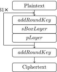
PRESENT is an ultra-lightweight block cipher, developed in 2007 [32]. It is a symmetric cipher, following an SPN structure, where the block length is 64 bits and key length can be either 128 bits or 80 bits. A round function consists of three operations: addRoundKey (xor of the state with the round key), sBoxLayer (substitution by 4-bit SBox, which we refer to as PRESENT SBox), andpLayer (bitwise permutation). After 31 rounds, there is one more addRoundKey, used for post-whitening. The whole process is depicted in Figure 2. Because of its lightweight char-acter, it is recommended to use 80-bit key length in order to keep the computation fast and energy efficient [32]. We will focus on this variant, denoted by PRESENT-80. For our implementation, we take pre-computed round keys which are already encoded and therefore, we omit the description of the key schedule here.
By definition, evaluations of pC,m,pC,bf,pC,sk are done on an
assembly implementation, thus it is important to specify what kind of implementation is used. The main properties of the implementation in our case study are as follows:
1) Each operation is implemented as a table look-up from memory.
Algorithm 2:Fault simulation algorithm.
Input :noOfIter:number of random plaintexts and key pairs to compute,C: (n,M,d, δ)−binary anticode, F: sequence of assembly instructions
implementingϕC(E),P: plaintext space,K: key space.
Output:SafeBitFlip (SafeBitFlip[m]= pC,m);pC,bf;pC,sk.
1 forInt k: 1 tonoOfIterdo
2 Take randomP∈ P, randomκ∈ K;
3 Compute the corresponding ciphertextE(P, κ); 4 forFault mask Int j: 1 to2ndo
5 forInt i: 1 to|F |do 6 forInstruction f inF do
7 Execute instructionf;
8 iff is the ith instructionandf has a destination registerthen
9 rf =rf⊕j;
10 ifoutput==⊥oroutput==E(P, κ)then 11 SafeBitFlip[HammingWeight(j)]++;
12 else
13 MissedBitFlip[HammingWeight(j)]++;
14 forInt i: 1 to|F |do 15 forInstruction f inF do 16 iff is the ith instructionthen
17 continue;
18 else
19 Execute instructionf;
20 ifoutput==⊥oroutput==E(P, κ)then 21 SafeSkip++;
22 else
23 MissedSkip++;
24 forInt m: 1 to ndo
25 SafeBitFlip[m]=SafeBitFlip[m]/(SafeBitFlip[m]+ MissedBitFlip[m]);
26 pC,bf=min
m SafeBitFlip[m];
27 pC,sk=SafeSkip/(SafeSkip+MissedSkip);
28 returnSafeBitFlip, pC,bf,pC,sk.
2) Before the table look-up, the destination register of an oper-ation is precharged to a zero so that single instruction skip will be protected.
3) The error message⊥is denoted by the value zero0.
We note that for PRESENT-80, pLayer can be considered as four parallel bitwise operations where each is a function:
F162 →F 16
2 .sBoxLayeris 16 parallel Sbox substitution operation: F42 →F
4
2.addRoundKey:F 64
2 ×F
64
2 →F
64
2 is a bitwise operation.
Furthermore, 64 and 16 are multiples of 4. Thus we can use code with cardinality 24 = 16. In particular, to apply fault resilient
anticode scheme with PRESENT-80, we use (n,16,d, δ)−binary anticodes.
10
Plaintext
addRoundKey
sBoxLayer
pLayer
addRoundKey
Ciphertext 31×
Fig. 2: Sequence of operations of PRESENT block cipher.
Fig. 3: One round of PRESENT.
subsequent round, thanks to the state-wise diffusion function. As illustrated in the figure, outputs of Sboxes 0,1,2,3 denoted by red color, will be inputs of Sboxes 0,4,8,12 in the next round. This property helps us to tailor the look up tables in a way that can provide more efficient space/time implementation compared to implementing the two layers separately. In the following, we will explain the design of such an implementation .
Encoded Round Function for PRESENT
In this part, we will explain the implementation of the round functions for fault resilient anticode scheme with PRESENT-80 by using (n,16,d, δ)−binary anticodes. Remark 3 justifies that we can split or merge multiple cipher operations while using the fault resilientC−map (Definition 10), preserving the correct data-flow.
The addRoundKey is a binary operation, xor-ing the key with the current state. Therefore, it can be directly implemented by an xor lookup table, similar to the implementation F of ϕC(g) in Section 5.1. ThesBoxLayer maps an input value to an output value, therefore the standalone implementation would be even easier than the xor. However, we have decided to merge sBoxLayer together with the pLayer, because the latter cannot be implemented in a straightforward way. The overview of this merged implementation is depicted in Figure 4, which explains how the first encoded nibble is obtained. The explanation of this approach is given below.
LetCbe an (n,16,d, δ)−binary anticode. The implementation ofΦC
pLayer◦sBoxLayerrelies on the xor lookup table and eight other tables, which can be divided into two groups:
1) Bit-extracting Sbox tables: This group has four ta-bles: T0, T1, T2, T3 such that T i takes a code-word, say EncoderC(x0x1x2x3) and returns the codeword
EncoderC(xsi000). If the input is not a codeword, the return
value will be⊥. Here we assume that after PRESENT SBox, x0x1x2x3becomesxs0xs1xs2xs3.
In other words, this group first computes an Sbox on the encoded data, and then extracts one bit – the bit position depends on which of the four tables is used. So, the output of these tables is the codeword corresponding to either 0 or 8. 2) Bit-shifting tables: This group has four tables as well:
T B0, T B1, T B2 and T B3. For a codeword of the form EncoderC(x000), T B0, T B1, T B2, T B3 return the code-wordsEncoderC(x000),EncoderC(0x00),EncoderC(00x0), EncoderC(000x), in their respective order. If the input is not a codeword, the return value will be⊥for all the four tables. In other words, the tables in this group provide bit shifting operations, that are necessary to finalize the pLayer. The outputs of tables T B0, T B1,T B2, T B3 can be codewords corresponding to 8, 4, 2, 1 or 0, depending on the value and the bit position.
After the Sbox is computed and the bit shifts on the resulting data are done, the data is combined back to 4-bit format by using an xor table – in total, three xor operations are required to combine the data. In the following, we will explain this process step-by-step.
Assume we haveEncoderC
a0a1a2a3b0b1b2b3c0c1c2c3d0d1d2d3
, representing a cipher state, where each letter represents one nibble of information. This is what happens:
1) EncoderC(a0a1a2a3) is passed to tablesT0,T1,T2,T3, the
four returned values are passed toT B0 and we get:
EncoderC(as0000),EncoderC(as1000),EncoderC(as2000),
EncoderC(as3000);
2) EncoderC(b0b1b2b3) is passed to tablesT0,T1,T2,T3, the
four returned values are passed toT B1 and we get:
EncoderC(0bs000),EncoderC(0bs100),EncoderC(0bs200),
EncoderC(0bs300);
3) EncoderC(c0c1c2c3) is passed to tablesT0,T1,T2,T3, the
four returned values are passed toT B2 and we get:
EncoderC(00cs00), EncoderC(00cs10), EncoderC(00cs20),
EncoderC(00cs30);
4) EncoderC(d0d1d2d3) is passed to tablesT0,T1,T2,T3, the
four returned values are passed toT B3 and we get:
EncoderC(000ds0),EncoderC(000ds1),EncoderC(000ds2),
EncoderC(000ds3).
Afterwards, we need three xor table lookups: 1) The first four encoded nibbles are given by
EncoderC(as0000)e⊕EncoderC(0bs000)
e
⊕EncoderC(00cs00)
e
⊕EncoderC(000ds0)
;
2) The second four encoded nibbles are given by
EncoderC(as1000)e⊕EncoderC(0bs100)
e
⊕EncoderC(00cs10)
e
⊕EncoderC(000ds1)
;
3) The third four encoded nibbles are given by
EncoderC(as2000)e⊕EncoderC(0bs200)
e
⊕EncoderC(00cs20)
e
⊕EncoderC(000ds2)
;
4) The fourth four encoded nibbles are given by
EncoderC(as3000)e⊕EncoderC(0bs300)
e
⊕EncoderC(00cs30)
e
⊕EncoderC(000ds3)
;
Heree⊕represents xor table lookup.
7.2 Results
EncoderC(c0 c1 c2 c3 )
cs0
0 0 )
cs1 )
0 0
cs2 )
0 0 0
cs3 )
0 0 0
0 0
EncoderC(
EncoderC(
EncoderC(
EncoderC(
EncoderC(b0 b1 b2 b3)
bs0 0 0 )
bs1 )
0 0 0
bs2 )
0 0
bs3 )
0 0
0
0
0
EncoderC(
EncoderC(
EncoderC(
EncoderC(
EncoderC(d0 d1 d2 d3 )
ds0
0 0
0 )
ds1)
0 0 0
ds2)
0 0 0
ds3)
0 0 0
EncoderC(
EncoderC(
EncoderC(
EncoderC( a0 a1 a2 a3
EncoderC( )
as1 0 0 )
as2 0 0 )
as3 0 0 )
0
0
0
as0 0 0 0 )
EncoderC(
EncoderC(
EncoderC(
EncoderC(
0 0 0 )
)
0 0 0
)
0 0 0
)
0 0 0
EncoderC(
EncoderC(
EncoderC(
EncoderC(
as0
bs0
cs0
ds0
EncoderC(as0bs0cs0ds0)
~
~
~
Fig. 4: Illustration of the implementation of PRESENT-80 sBoxLayer and pLayer in fault resilient anticode scheme.
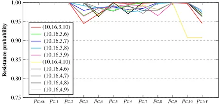
To analyze the performance of different anticodes in fault resilient anticode scheme, for each anticode in Table 4, we run Algorithm 2 using implementation of PRESENT-80 following the specification stated in Section 7.1. To decide the inputnoOfInter, we randomly picked 10 anticodes and executed the algorithm with different values of noOfInter. Our results showed that for noOfInter≥200, the change in the output probabilities for diff er-ent values of noOfInterbecame negligible (<10−6). Therefore,
we have setnoOfInter=200 for our evaluation of each anticode. The analysis results for anticodes (Table 4) with n = 8,d = 2,3, andn=10,d=2 with variousδvalues are stated in Figures 5 and 6, respectively. Additional results forn = 8,d = 2,3, n = 9,d =2,3,4, andn=10,d =3,4 are stated in Appendix C. We have the following observations.
1) The instruction skip resistance probability is 1 for all anti-codes. This is due to the precharge of destination register of our implementation specification.
2) The improvement of using a longer length for encoding the data is obvious – bit flip fault resistance probabilities faults for length 8 go up to≈0.933, for length 9 up to≈0.966, and for length 10 up to≈0.979.
3) Forn=8,9,10 the anticode with the best performance (i.e. the highest bit flip fault resistance probability pC,bf) are
an-ticodes with parameters (8,16,3,6),(9,16,3,7),(10,16,3,8) respectively.
4) Every (8,16,4,8)−binary anticode has a property that 8−bit flip has a probability 1 of beingmissed, i.e. pC,8 = 0. We
note that this finding is in accordance with the one described in [18].
Remark 10. • The anticodes that achieve the best bit flip fault resistance probabilities satisfy both conditions 3-a and 3-b in Lemma 2.
• Comparing the last two columns of Table 4, we can see the theoretical analysis of one operation does give insights on what kind of parameters to look for.
• However, the theoretical analysis results differ from the simulated probabilities for most of the codes, showing that the analysis of one code snippet cannot capture what happens when a full cipher implementation is considered. To be more specific, the implemented tables can provide an output which follows a non-uniform distribution over the codewords, such as bit-extracting and bit-shifting tables in the case of the PRESENT-80 implementation detailed in Section 7.1.
There-pC,sk pC,1 pC,2 pC,3 pC,4 pC,5 pC,6 pC,7 pC,8 pC,bf
0.75 0.80 0.85 0.90 0.95 1.00
Resistance
pr
obability (8,16,2,4) (8,16,2,5) (8,16,2,6) (8,16,2,7) (8,16,2,8) (8,16,3,6) (8,16,3,7) (8,16,3,8)
Fig. 5: Simulated results for anticodes withn=8,d=2, 3.
pC,sk pC,1 pC,2 pC,3 pC,4 pC,5 pC,6 pC,7 pC,8 pC,9 pC,10 pC,bf
0.75 0.80 0.85 0.90 0.95 1.00
Resistance
pr
obability
(10,16,2,10) (10,16,2,4) (10,16,2,5) (10,16,2,6) (10,16,2,7) (10,16,2,8) (10,16,2,9)
Fig. 6: Simulated results for anticodes withn=10,d=2.
fore, it shows the importance of simulating the cryptographic implementation execution for getting more precise insights on the code robustness.
8 Selection ofAnticodeParameters
Now a natural question to ask is how to choose the parameters for anticodes in general, e.g. for different device architectures and security requirements. We propose the following guidelines:
12 2) Number of codewords (M): Number of codewords is, on
the other hand, independent on the underlying architecture – it does not affect table size or require specific register size. The designer needs to take the cipher and the security requirements into account when deciding on number of codewords. For example, in case of PRESENT, the operations are computed on nibbles and therefore, 16 codewords is the preferred number, providing a good trade-off between security and execution speed. Lower number of codewords would mean higher security, but slower speed since the operations need to be carried on smaller chunks of data. 3) Distance (d) and maximum distance (δ):These parameters
are not dependent on the device architecture, but can affect the resulting security significantly.
The first, and obvious selection criterion is whether a code with certaind, δexists for somenandM. For this purpose, Lemma 3 provides an answer, with results for n = 8,9,10 stated in Table 2.
Another selection criterion is whether some particular fault models can be prevented by other means – suppose we have an additional error detecting module that can detect 2 or 4 bit-flips. Then, we can use (8, 16, 2, 4)-anticode from Figure 5, since only these two models are undetected using this code. Furthermore, the selection is also dependent on the attacker model assumption. In case we want to build an implementa-tion resistant against specific fault model, e.g. nibble flip [33], then we would like to select an anticode with the highest 4−bit flip fault resistance probability,pC,4.
For any case, while the values ofn,Mcan be decided before the actual cipher implementation,dandδshould be decided after running the evaluation in Section 6.2.
9 Discussion
Memory and Speed Trade-Offs
Table 4 shows that if the anticode C has longer length, fault resilient anticode scheme using C has better fault resistance properties. On the other hand, it also means a bigger memory con-sumption that increases sub-exponentially with the code length. In the following, we will discuss the overheads.
When it comes to speed, the fastest non-bit sliced 8-bit implementation of PRESENT-80 requires 8,721 clock cycles [34], out of which≈ 1,248 is a key schedule (since we consider the round keys already in the memory, we will only count 7,473 clock cycles for the implementation from [34]). In case the selected code can be fully implemented in the SRAM (and therefore, a table look-up operation LD takes 2 clock cycles), fault resilient anticode scheme implementation takes 9,424 clock cycles (≈ 26.1% overhead). In case all the look-up tables are stored in the flash memory (LMP instruction taking 3 clock cycles has to be used), the approach takes 13,640 clock cycles (≈82.5% overhead). Therefore, compared to the most popular time redundancy that repeats the encryption twice and compares the results [3], the encoding method provides reasonable timing overheads, especially if the look-up tables can be stored in the SRAM.
While the speed of the implementation might be reasonable, the memory overheads quickly grow to sizes that are not practical for real-world cryptography. It has to be noted that even if the code length is smaller than the memory address length, the table normally has to occupy the size according to this length, otherwise the unused bits in the address could be faulted and would point
to another part of the memory that is used for a different purpose. Therefore, if we want to use a binary anticode of length 6 in a 16-bit addressing space device, the constructed table still has to be of size of 8×8 bits. For such architecture, codes longer than 8 bits would not be possible – in case of code length is between 9−16, we need a 32-bit addressing space. Also, number of codewords does not affect the memory requirements since the table size for the same code length is constant, only the number of non-zero values will change with different number of codewords. Efficient implementation of encoding schemes therefore still remains an open problem.
Table 3 provides memory requirements for some standard cryptographic operations. Since block ciphers combine several functions in order to achieve the security requirements for confu-sion and diffusion, several tables normally have to be stored in the memory. For example, the PRESENT implementation in Section 7 uses one xor table and eight shifting tables for the combined pLayer and sBoxLayer, resulting in total of 81,920 bytes of memory. To test the feasibility, we made an implementation for Atmel ATmega328P, an 8-bit microcontroller. However, only the eight smaller tables could fit into the device memory, while the big xor table had to be put on an external EEPROM module (256 Kbit Microchip 24LC256).
TABLE 3: Overheads for implementing fault resilient encoding scheme.
Operation Type Code Length Required Memory (B)
Unary (Sbox, shifts) ≤8 2,048
≤16 524,288
Binary (XOR, AND, ≤8 65,536
modular addition) ≤16 33,554,432
Instruction Modification
Recently, a fault attack approach utilizing instruction replacement has emerged [35]. Up to date, there is no dedicated protection against such fault model. In [35], the attacker has to change the instruction opcode that specifies the operation – e.g. in case of changingADDtoSUBin AVR, as presented in [35], the instruction opcode needs to be changed from000011to000110. In case the standard instructions are used, if the attacker is able to achieve this model on a particular device, she can do that for any imple-mentation executed on such device. However, in the case of the table look-up based fault resilient anticode scheme, the means to achieve the instruction replacement that result to executing another operation are different. Each operation is executed as fetching the result from a table and hence the address of this table specifies this operation. Instead of changing the instruction opcode, the attacker needs to know the table address she wants to change the operation to. Such address would vary from implementation to implementation and it is not trivial to predict whether the attacker would be able to achieve such precise change.
Cache Timing Attacks