Available Online atwww.ijcsmc.com
International Journal of Computer Science and Mobile Computing
A Monthly Journal of Computer Science and Information Technology
ISSN 2320–088X
IMPACT FACTOR: 6.017
IJCSMC, Vol. 6, Issue. 12, December 2017, pg.142 – 150
Survey on Image Enhancement
Varsha Sahu
Dept. of Information Technology SATI, Vidisha, India [email protected]
Abstract: - The contrast enhancement method frequently play crucial role in image processing. Image enhancement is the task to process an image so that the result is more suitable than the original image for specific applications. The alteration usually requires interpretation and feedback from a human evaluator of the output resulting image. Image enhancement is to improve the image quality so that the resultant image is better than the original image for a specific application or set of objectives. The channel division technique enables operation on the content of the image and therefore content such as edges and other subtle information can easily be enhanced. This paper also presents a review of various methods for contrast enhancement. The channel division technique is based on the analysis of the content in several regions and create transformation function for separate region. This paper also present method which divides the image into sub image then perform enhancement. The major difference among the methods in this family is the criteria used to divide the input histogram. Brightness preserving Bi-Histogram Equalization (BBHE),weighted mixture of global and local transformation, sub block histogram equalization, recursively separated method are based on the split image in its sub images then perform enhancement. In image dependent brightness preserving method curvelet transform function used. Brightness preserving dynamic histogram equalization is an extension of histogram equalization.
Index Terms – Contrast enhancement, histogram equalization, channel division, bihistogram equalization, POSHE, curvelet transform, global transformation function, local transformation function, intensity pair.
I. INTRODUCTION
and unnatural image are still produced. Another popular method is weighted mixture [6], where the enhancement method is based on the weighting mixture of local and global transformation function based on mapping function. This method gives better increment in image enhancement. But still suffer the drawback of shifting mean value in local transformation. The method based on classification of image characteristics is adaptive image enhancement [7]. Another method is the dynamic histogram equalization for image contrast enhancement [8], which is an extension of HE that produce output image with mean intensity almost equal to mean intensity of the input image. The modified technique called brightness preserving dynamic fuzzy HE (BPDFHE) [9], uses fuzzystatistics of digital images for there representation and processing. In most cases the contrast improvement provided by BPDFHE is credibly more than that provided by BPDHE. Another complex methods is the multiscale retinex algorithm (MSR) [10],which is fast version of retinex algorithm [11].
II. CHANNEL DIVISION TECHNIQUE
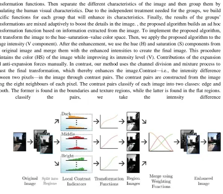
Content-aware method that analyzes the contrast in the boundaries and in the texture regions to produce ad hoc transformation functions. Then separate the different characteristics of the image and then group them by simulating the human visual characteristics. Due to the independent treatment needed for the groups, we build specific functions for each group that will enhance its characteristics. Finally, the results of the groups’ transformations are mixedadaptively to boost the details in the image. , the proposed algorithm builds an ad hoc transformation function based on information extracted from the image. Toimplement the proposed algorithm, first transform theimageto the hue–saturation–value color space. Then, we apply the proposed algorithm to the image intensity (V component). After the enhancement, we use the hue (H) and saturation (S) components from the original image and merge them with the enhanced intensities to create the final image. This procedure maintains the color (HS) of the image while improving its intensity level (V). Contributions of the expansion and anti-expansion forces manually. In contrast, our method uses the channel division and mixture process to adjust the final transformation, which thereby enhances the image.Contrast—i.e., the intensity difference between two pixels—in the image through contrast pairs. The contrast pairs are constructed from the image using the eight neighbours of each pixel. The contrast pairs classify of each image into two classes: edge and smooth. The former is found in the boundaries and texture regions, while the latter is found in the flat regions. To classify the pairs, we take the intensity difference
Fig. 1. Abstraction of the proposed method
Furthermore, the set of edge contrasts for the pixel (x,y) and intensity i, is defined by
( ) * ( ) ( ) ( ) ( ) ( ) ( ( ) ( ))+ (3)
The accumulations for each intensity channel LCI, and are projected by replacing f with as follows:
( ) ∑ ( )
∑ ( )
(4)
( ) ( ) ( ( )) (5)
Grouping the contrast pairs into intensity channels is not sufficient to produce the best enhancement, as there may be channels with similar properties. We propose to mix the channels with similar characteristics into region channels. Consequently, a region channel is a mix of intensity channels that share some characteristics. Hence, an image may have R different region channels that are defined by
∑
(6)
Where is the region channel transformation, is the transformation function for each intensity channel i and are
lower and upper bound (intensities) for the region channel [the ( ) and ( ) channel may share there upper and lower bounds with the rth channel].Finally, the enhanced image is a mixture the region channels, each channel has a different weighting function that emphasizes its characteristics. The final transformation function can be computed as
( ) ∑ ( ) ( ) (7)
Where is the weighting function for the rth region channel, and ( ) indicates the ith position in the rth region channel transformation function. Finally, the image is enhanced by
( ) ( ( )) (8)
The proposed method could not recover information from the shadowed or dark areas of images that had near black intensities. Some parts of the image were still enhanced, but significant amount of near black intensities produced undesired effects in the high intensities
III. BRIGHTNESS PRESERVING BI-HISTOGRAM EQUALIZATION
Bi-histogram equalization based on the division of the input image into sub images based on the mean. One part has the sample less than mean and other part has sample greater than mean. The histogram equalization on the both image are applied separately and at last step both sub images are merged. Suppose a image with (L-1) level is split into two sub images and based on mean m, then
(9)
Where
* ( ) ( ) ( ) + (10)
* ( ) ( ) ( ) + ( )
So from above equation it is clear that is composed of ( )and is composed
Then probability density function of sub images are given below
( ) (12)
( ) (13)
In which and represents the no of in and ,and and are the total numbers of samples in input image.
The respective CDF for and are given below
( ) ∑ ( ) (14)
And ( ) ∑ ( ) (15)
Where
Cdf is a transform function. Now the transform function exploiting the cdf.
( ) ( ) ( ) (16)
( ) ( ) ( ) ( )
The decomposed sub images are equalized independently based on above transform function and then resulting sub images are composed to form complete histogram. Suppose Y represent the output image then
* ( )+ (18) ( ) (19)
Although BHE increase the performance of HE but sometime this method suppresses the over enhancement problem. Unnatural images however still occur.
IV. SUB BLOCK HISTOGRAM EQUALIZATION
In this method a low pass filter type mask is used to get a nonoverlapped sub block histogram equalization function to produce the high contrast associated with local histogram equalization. The low pass filter type mask is realized by partially overlapped sub block histogram equalization(POSHE).Since with the proposed method, the sub block are much less overlapped the computation overhead is reduced by a factor of about 100 compare to that of local histogram equalization. The procedures of Poshe are given below:
1. Define an MXN sized output image array for MXN input image and set all value to zero.
2. Assign a sub-block.For computational simplicity a subblock size is selected to be equal to the quotient of the input image size is divided by a multiple of 2.Assign the sub block origin using the input image origin.
3. Perform local histogram equalization for each sub block and the result are accumulator in the output image array. 4. Increase the horizontal coordinate of the sub block origin by the horizontal step size and repeat step 3.When the
horizontal coordinate equals the horizontal input image size, increase the vertical coordinate of the sub block origin by the vertical step size and repeat horizontal POSHE. Repeat whole procedure until POSHE covers the whole input image.
5.
After sub block histogram equalization finished, divide each pixel value in the output image array by its sub block histogram equalization frequency.V. BRIGHTNESS PRESERVING HISTOGRAM EQUALIZATION
This method increases the enhancement while preserving the image detail. In this method curvelet transform function and histogram matching technique are used. The curvelet transform are used to fine the bright regions in the image. Firstly find out the bright region in the image, then histogram of the identified image are compared with the histogram of the original image. For this purpose wraparound discrete transform function are used. The curvelet transform is used for region identification and hard threshold is used for region separation. Let represent space domain curvelet then the curvelet transform of the image I is given by
(20)
Where * denotes the convolution operator. An image that contains mostly bright region is given by
( ( )) (21)
Where represent i direction subband at scale. represent scale parameter for scale subband.The identified image is
identified by hard threshold parameter to separate the identified regions from other region of the original image.The parameter is image dependent and typically is varies from0 to 1.The separated image
( ) (22)
The histogram of the image is identified by
( ) (23)
And its cdf is given by
( ) ∑ ( ) (24)
( )
Histogram matching or histogram specification is a non linear transformation method which changes shape of a given histogram to a desired one. Let us assume ( ) is histogram of original image and ( ) represent probability density function of desired image then
( ) (25)
A histogram matching between ( ) and ( ) are given by
( ) ∫ ( ) (26)
( ) ∫ ( ) (27)
Absolute mean brightness error and peak signal noise ratio is used to access the effectiveness of the proposed method. Formal access the degree of brightness while later preserving the degree of contrast enhancement. PSNR value of this method is better to other. This method is not always giving the best AMBE vale it preserves the brightness in the subjective sense.
VI. Image enhancement technique using weighted mixture of global and local transformation function
The basic idea of global transformation function is to divide input histogram into two parts based on the mean. These sub images are than further divided into sub images based on the mean and level of recursion r. The resulting histogram regions are equalized independently. Thus global transformation function is obtained as
( ) ( )
∑ ( ) ∑ ( )
(28)
Where g denotes the intensity value, and are lower and upper bound of histogram ( ) is global transformation
function. Local expansion function from intensity pairs distribution method exploits the neighbourhood information of all pixels to generate a global intensity mapping function. Different parts of image have different statistical characteristics, so block wise approach used to handle local information more effectively. Within each block generate the set of intensity pair
{( ), ( ) ( ) ( )} from a pixels 8-conneted neighbours.
In a 2D image, many edge pairs exist near the edges. Therefore we accumulate all expansion forces between the edge pairs. The anti expansion force ensures the smoothness for homogenous regions in net expansion force. The net expansion force, F is obtained by
( ) ( ) [ ] (29)
( ) ( ) [ ] (30)
(31)
Where ( ) is expansion forces and ( ) is anti expansion force. Then the local expansions function from the intensity pair distribution.
( ) ∑ ( ) (32)
A weighted mixture of the expansion function and the global transformation function is computed by
( ) ( ) ( ) ( ) (33)
Where K is the weight value [0.0, 0.1].
This method give greater incremented in the image enhancement. But has one drawback. In the final mapping function M (.) the local transformation function causes the output mean value can be shift and thus deviates from preserving the input mean brightness.
VII. ADAPTIVE IMAGE ENHANCEMENT TECHNIQUE BASED ON THE IMAGE CHARACTERISTIC
This method is based on the classification of the image characteristics. Firstly high pass filter (Laplace transform) is performed and after specification first order classifying of the image employed. The high pass filter is used to sharpen the edge of the image for low threshold value and low pass filter is used to smooth the image for high threshold image, Then second order classifying is used to adjust the brightness of the image based on the histogram of the first order classifying. It increased or decreased the brightness based on the result of first order classifying. At last step HE method of contrast enhancement applied to produce the output. It consists of four major function block such as sharpening pre-processing (SE), first order classifying intensity enhancement (FCIE), second order classifying and intensity enhancement (SCIE) and contrast enhancement.
Image sharpening pre-processing:-The second order partial differential equation along the 0, 45, 90,135 degree directions are expressed as
( ) ( ) ( )
( ) ( ) ( )
( ) ( ) ( ) (34)
So the result of laplace filter is obtained by summing above four components:
( ) ( ) ( ) ( ) ( ) ( ) ( )
( ) ( ) (35)
All the values are scaled to the interval [0,255] by multiplying each pixel by the quantity 255/max, in the modified minimum modified values.
The first order classifying and intensity enhancement:-Let us assume MAXL and MINL are two positive threshold value. MAXL show the maximum threshold and is set to 32 and MINL represent minimum threshold is set to 16 based on experience.
If the low threshold image (AVEFL<MINL)
The output of the first order classifying and intensity enhancement is defined as
( ) ( ) (36)
is positive factor and set to 0.25.
If the image belong to high threshold image (AVEF>MAXL)
Then the gauss filter belongs to low pass filter and its operator is weighted from the mast given below
{
} (37)
The second order classifying and intensity enhancement:-To adjust the brightness of the image it used. If (AVEFI<MINI) then it is considered that the brightness of the image is so dark that improves by the rate of β. ( ) The output of SCIE is defined as
( ) ( ) ( ) (38)
Β is a positive factor set to 0.125.
If (AVEFI˃MINI) then the brightness of the image is considered so bright that reduces by the rate of β.Then
( ) ( ) ( ) (39)
If AVEFI is between MAXI and MINI then the brightness of the image is neither too dark nor to bright.
( ) ( ) (40)
Contrast enhancement:-HE is used for contrast enhancement.
And its cumulative density function is given by
( ) ∑ ( ) (42)
Thus the transform function of HE defined as
( ) ( ) ( ) (43)
It is supposed that
( ) (44)
Is define as equalized output image, then
( ) * ( ( )) ( ) + (45)
VIII. CONCLUSION
The comparative study of different method shows that content aware methods can improve images from a verity of different enhancement function based on the content of the image. Histogram equalization based method shows that the cases which require higher brightness preservation and now handled well by histogram equalization bi-histogram equalization, brightness preserving histogram equalization and sub block histogram equalization have properly enhanced. Image enhancements using weighted mixture of global and local transformation function give greater improvement in resultant image. Through these methods good contrast enhancement can be performed. The method based on image characteristic is adaptive image enhancement technique. It consists of major function block.
R
EFERENCES
[1] R. C. Gonzalez and R. E. Woods, Digital Image Processing, 3rd ed. Upper Saddle River, NJ: Prentice-Hall, 2006.
[2] Adin Ramirez Rivera, Byungyong Ryu, and Oksam Chae ―Content-Aware Dark Image Enhancement Through Channel Division‖, IEEE Transactions on Image Processing, Vol. 21, No. 9, pp. 3967 – 3980, September 2012.
[3] Y.-T. Kim, ―Contrast enhancement using brightness preserving bihistogram equalization,‖ IEEE Trans. Consumer Electron., vol. 43, no. 1, pp. 1–8, Feb. 1997.
[4] Kim Y., Kim S., and Hwang H., ―An Advanced Contrast Enhancement Using Partially Overlapped Sub: Block Histogram Equalization,‖ Computer Journal of IEEE Transaction Circuits System Video Technology, vol. 11, no. 4, pp. 475- 484, 2001. [5] P. Rajavel, ―Image dependent brightness preserving histogram equalization‖ IEEE transaction on consumers electronics, Vol. 56, No. 2,May 2010
[6] Hasanul Kabir, Abdullah Al-Wadud, and Oksam Chae ―Brightness Preserving Image Contrast Enhancement Using Weighted Mixture of Global and Local Transformation Functions‖, The International Arab Journal of Information Technology, Vol. 7, No. 4, pp. 403 - 410 ,October 2010.
[7] Xiaodong Xie, Zaifeng Shi, Wei Guo, and Suying Yao ―An adaptive image enhancement technique based on image characteristic‖.
[8] Haidi Ibrahim and Nicholas Sia Pik Kong ―Brightness preserving dynamic histogram equalization for image contrast enhancement‖ IEEE transaction on consumer electronics,Vol. 53,No. 4,NOVEMBER 2007.
[9] Debdoot Sheet,Hrushikesh Guard,Amit Suveer,Manjunatha Mahadevappa,Jyotirmoy Chatterjee ―Brightness preserving dynamic fuzzy histogram equalization‖ .
[10] D. J. Jobson, Z. Rahman, and G. A. Woodell, ―A multiscale retinex for bridging the gap between color images and the human observation of scenes,‖ IEEE Trans. Image Process., vol. 6, no. 7, pp. 965–976, Jul. 1997.
[12] E. H. Land and J. J. McCann, ―Lightness and retinex theory,‖ J. Opt.Soc. Amer., vol. 61, no. 1, pp. 1–11, Jan. 1971.
[13] G. Orsini, G. Ramponi, P. Carrai, and R. Di Federico, ―A modified retinex for image contrast enhancement and dynamics control,‖ in Proc. Int. Conf. Image Process. vol. 3. Sep. 2003, pp. 393–396.
[14] R. Sobol, ―Improving the retinex algorithm for rendering wide dynamic range photographs,‖ J. Electron. Image. vol. 13, no. 1, pp. 65–74, 2004.
[15] L. Tao and V. Asari, ―Modified luminance based MSR for fast and efficient image enhancement,‖ in Proc. 32nd Appl. Imagery Pattern Recognition. Workshop, Oct. 2003, pp. 174–179.
[16] Chesnokov, ―Image enhancement methods and apparatus therefore,‖ U.S. Patent 7 302 110, Apr. 10, 2002.
[17] Haidi Ibrahim, and Nicholas Sia Pik Kong, ―Brightness preserving dynamic histogram equalization for image contrast enhancement‖, IEEE Trans. Consumer Electronics, vol. 53, no. 4, pp. 1752 - 1758, November 2007.
[18] K. Panetta, E. Wharton, and S. Agaian, ―Human visual system-based image enhancement and logarithmic contrast measure,‖ IEEE Trans. Syst., Man, Cybern. B, vol. 38, no. 1, pp. 174–188, Feb. 2008.
[19] S. Agaian, K. Panetta, and A. Grigoryan, ―Transform-based image enhancement algorithms with performance measure,‖ IEEE Trans. Image Process., vol. 10, no. 3, pp. 367–382, Mar. 2001.
[20] S. Agaian, B. Silver, and K. Panetta, ―Transform coefficient histogram-based image enhancement algorithms using contrast entropy,‖ IEEE Trans. Image Process., vol. 16, no. 3, pp. 741–758, Mar. 2007.