Grid Connected PV System by Single Stage
Abdul Matin Mistry1, Prabodh Khampariya2
PG Student [EPS], Dept. of EE, Sri SatyaSai University of Technology & Medical Sciences, Sehore, India1 Associate Professor, Dept. of EE, Sri SatyaSai University of Technology & Medical Sciences India2
ABSTRACT: Single- Phase, Single- stage current source inverter based photovoltaic system for grid connection without using transformer is proposed. This system is used for tracking the maximum power point and interfacing the photovoltaic array into the grid. The maximum power point tracking (MPPT) is maintained with the software controller. A proportional resonant controller to control the current injected into the grid. A double tuned parallel resonant circuit is used to attenuate the harmonics at the inverter dc side .CSI has been used to meet the grid requirements without using a high dc voltage or bulky transformer. CSI has become a preferred topology for interfacing PV system to the ac power grid, because of CSI provides a continuous dc side current. The energy stored element of CSI has a longer life time than VSI.MPPT is used to improve the system performance during normal and varying weather conditions.
.
KEYWORDS: current source inverter(CSI),MPPT, photovoltaic (PV). .
I.INTRODUCTION
Due to the environmental issues, renewable energy source is the main thing in researchers. The most important renewable energy is a photovoltaic (PV)system, because of suitable in distributed generation, satellite system and transportation. In distributed generation applications, the PV system operated in grid connected mode is very popular. In this grid connected mode, maximum power is from the PV system to supply into the grid. A two stage grid connected PV system utilizes two conversion stages: a dc/dc converter for Boosting and conditioning the PV output voltage and tracking the MPP, and dc/ac inverter for interfacing the PV system to the grid. In this method, high-voltage PV array is not required, because of dc high-voltage boosting stage. This two stage suffers from reduced efficiency, higher cost and larger size. The conventional voltage source inverter (VSI) is the most commonly used in grid connected PV system. However, the voltage buck properties of the VSI increase the necessity of using bulky transformer or high dc voltage .However, the electrolytic capacitor, which presents a critical point of failure. The three phase grid connected CSI, which affect the MPPT, reduce the PV life time and associated with odd order harmonics. Therefore, eliminating the harmonics on the dc side various techniques have been proposed to reduce the harmonics CSI PV applications. The Nonlinear pulse width modulation (NPWM) has been proposed to improve the harmonics mitigation. The power oscillating effect is mitigated by using carrier signal on pulse width modulation(PAM).
These techniques not suited in single stage grid connected system because of dc current oscillation is large, which reduces the system loss and PV life time. In a single stage connected system, the PV system consists of single conversion unit (dc/ac inverter) to track the maximum power point (MPPT) and interface the PV system to the grid. In this paper CSI has been proposed ,because dc input current is continuous and CSI voltage boosting capability allows a low voltage PV array to be grid interface without need of a transformer less or additional boost stage. A double tuned resonant is used to mitigate the harmonics at the dc side. The control structure consists of MPPT, and current loop and voltage loop. The effectiveness and robustness of the proposed system, simulation and practical implementation.
II.SYSTEM DESCRIPTION
Fig. 1Single phase grid connected CSI.
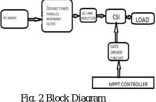
Fig. 2 Block Diagram
Our aim is synchronize the PV array and the grid. The PV array produces the dc voltage depends upon the irradiation and ambient temperature. This dc voltage flows through the double tuned parallel resonant filter and dc link inductor.
A. DOUBLETUNEDRESONANTFILTER
Fig. 3 Double Tuned Resonant Filter
III.PV ARRAY DESCRIPTION
PV array consists of number of PV modules connected in parallel. Each PV module consists of number of PV cells connected in series .PV cell consists of current source shunt with diode. The ripple in dc side current is filtered and controlled by dc side inductor.
A. GRID CONNETION OF PV SYSTEM
In the grid connected PV system, PV array and grid will be synchronized. The grid control technique is a single conversion. That is dc to ac inverter. The methodology of the system is PV array system and output parameters are analysed by suitable controller and it produces corresponding effective PWM pulses for generation of ac voltages.
B. PV SYSTEM DESCRIPTION
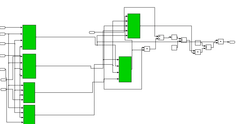
Fig.4 Simulink model for CSI based Grid connected PV system
Fig. 5 Simulink Model For PV Module - I
Fig. 6 Simulink Model For PV Module - II
C. SYSTEM PARAMETERS
To design a grid connected PV system using CSI, the relationship between the PV output voltage and grid voltage. PV output power is equal to the grid power. PV output voltage should not exceed half the grid peak voltage. The CSI is utilized to track the PV MPP and to interface the PV system to the grid.
Resonant filter inductor,(L1)=5mH Resonant filter inductor(L2)=10mH
Resonant filter capacitor (C1)=125microfarad Resonant filter capacitor (C2)=250microfarad DC link inductor L dc= 5mH
AC line inductor= 1 mH
AC line capacitor= 20microfarad
IV.CSI BASED PV CONTROLLER
A grid connected CSI based PV system is designed to control the dc and ac side current. The power is fed to the grid is equal to the maximum power from the PV array under normal and varying weather conditions. The phase locked loop (PLL) is used to synchronize the PWM and control of the CSI to the grid voltage also PID controller are used to process the errors between output and input current.
A. PHASELOCKEDLOOP
Fig. 7 Phase Locked Loop
The ac variables are sinusoidal function of the grid frequency in steady state. In this fig.6 shows a angular speed is adjusted by grid frequency. This is achieved by PLL. The input of the PLL is grid voltage and output is reference current in to the pulses.
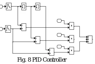
B. PID CONTROLLER
Fig. 8 PID Controller
V. MODIFIED CARRIER BASED PWM
Fig. 8 Modified carrier based PW
Modified carrier based PWM is proposed to control the switching pattern for the single phase grid connected CSI. To provide a continuous path for the dc side current, at least one top switch in either arm and one bottom switch must be turned on during every switching period. In this fig. 8 shows reference and carrier waveform along with switching patterns. The carrier with solid line. The straight for upper switches while dashed line is lower switches and shifted by 180°.The switching action of each IGBT is equally distributed during every fundamental period.
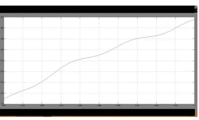
VI. PV OUTPUT AND RESULT
Fig. 9 PV Output Voltage
A. GRID VOLTAGE WAVEFORM
Fig. 10 Grid Voltage
B. GRID CURRENT WAVEFORM
Fig. 11 Grid Current
C. OUTPUT VOLTAGE AND CURRENT WAVEFORM
Fig. 12 Output Voltage and Current
Fig. 10,11 & 12 shows the Grid Voltage,Grid Current & Output Voltage respectively.Here Output Voltage is 230 V. These values are also dependent on PV generation and indirectly to the irradiance.
VII.CONCLUSION
REFERENCES
[1] Y. Bo,L.Wuhua,Z. Yi and H. Xianging,”Design and analysis of a grid connected photovoltaic power system”,IEEE Transaction on Power Electronics, Vol. 25 No. 4, pp. 992-1000,Apr. 2010
[2] S.B. Kjaer,J.K. Pedersen and F.Blaabjerg,”A review of single phase grid connected inverters for photovoltaic modules”,IEEE Transactions on Industrial Applications Vol. 41 No.5,pp. 1292-1306,Sep. – Oct. 2005
[3] S. Jain and V. Agarwal, “A single stage grid connected inverter topology for solar pv systems with maximum power point tracking”,IEEE Transactions on Power Electronics, Vol. 22 No. 5,pp 1928-1940,Sep. 2007
[4] E. Villanueva, P.Correa,J.Rodriguez and M.Pacas “Control of single phase cascaded H-bridge multilevel inverter for grid connected pv system” IEEE Transactions on Industrial Electronics Vol. 56 No. 11 pp. 4399-4406,Nov. 2006
[5] W.Tsai-Fu,C. Chih-Hao, L. Li-Chiun and K. Chia-Ling “Power Iosscomparison of single and two stage grid connected pv systems”,IEEE Tran. On Energy Conversion, Vol. 26 No. 2 pp.707-715,June-2011
[6] Trishan Esram and Patrick L. Chapman “Comparison of photovoltaic Array Maximum Power Point Tracking Techniques” IEEE Transactions On Energy Converion, Vol. 22 No. 2.pp. 439-449