Article
Processing BIM and GIS models in practice:
experiences and recommendations from a GeoBIM
project in the Netherlands
Ken Arroyo Ohori1,*, Abdoulaye Diakité2, Thomas Krijnen3, Hugo Ledoux1and Jantien Stoter1
1 Delft University of Technology 2 The University of New South Wales 3 Eindhoven University of Technology
* Correspondence: [email protected]
Abstract:It is widely acknowledged that the integration of BIM and GIS data is a crucial step forward for future 3D city modelling, but most of the research conducted so far has covered only the semantic aspects of GIS-BIM integration. We present here the results of the GeoBIM project, in which we tackled three integration problems focussing instead on aspects involving geometry processing: (i) the automated processing of complex architectural IFC models, (ii) the integration of existing GIS subsoil data in BIM, and (iii) the georeferencing of BIM models for their use in GIS software. All the problems have been studied using real world models and existing datasets made and used by practitioners in the Netherlands. For each problem, we expose in detail the issues we faced, our proposed solutions, and our recommendations for a more successful integration.
Keywords:gis; bim; ifc; citygml; integration; interoperability; geometry
1. Introduction
Geographic information systems (GIS) have long been used to model the environment and to perform 2D spatial analyses of large areas. However, with the increasing availability of computing power, inexpensive data acquisition methods, and automated workflows that generate detailed 3D data, GIS models have become increasingly detailed and have started to contain detailed models of individual buildings—the traditional domain of building information modelling (BIM).
At the same time, the same increase in computing power and the availability of better software have enabled once rare BIM methodologies to be applied on a large scale, disrupting more traditional building design platforms based on 2D drawings. As users of BIM software want to incorporate the surrounding features of a building or another structure into their workflow, it is only logical that the BIM domain is currently enhancing its standards and software to support environmental information such as infrastructure1, and that BIM users increasingly turn to existing GIS datasets containing this environmental information. Both domains are thus now overlapping, increasingly modelling the same objects, even if the data is represented and stored in rather different ways.
While the GIS and the BIM domains clearly overlap when the modelling of cities is concerned, each domain retains its own focus and has its own characteristics. The BIM domain focuses on information about the design and construction of building sites, and thus has very detailed and semantically rich information about all the physical elements that comprise an individual building as it is designed or built. Meanwhile, GIS represent information about the environment ‘as built’ (or
1 http://www.buildingsmart-tech.org/infrastructure
as captured) at different points in time, thus yielding less detailed but regularly updated datasets covering wide regions.
Due to the overlap in the features that are modelled in both domains, as well as their differing strengths and weaknesses, it is widely acknowledged that the integration of data from both domains is beneficial and a crucial step forward for future 3D city modelling [?]. This integration can avoid unnecessary efforts in redundant modelling and allow for new data flows in both directions. In this way, more detailed BIM data can feed more general GIS data, and GIS data can provide the context that is usually missing in BIM data. By pursuing the integration of GIS and BIM data, many ideas become possible:
• with contextual GIS information, BIM methodologies can be better applied to infrastructural works;
• more detailed 3D city models can be built by reusing BIM data;
• smart city concepts can perform integrated reasoning on terrain, buildings and city infrastructure;
• and spatial analyses can support multiple levels of detail and the complete life cycles of objects.
Despite this desire for integration, the disciplines of GIS and BIM are currently disconnected by their modelling paradigms, software tools and open standards, such as CityGML for GIS and IFC for BIM (Section2.1). Consequently, GIS and BIM datasets differ fundamentally with respect to their semantics, geometry and level of detail, and because of the different modelling approaches of both, there is not one optimal nor uniform conversion between the information models. Even as researchers and practitioners have studied how to best share information between BIM and GIS and how to address all the differences from different perspectives (Section2.2), it is still very hard (if not impossible) to share 3D information among different users throughout the life cycle of urban and environmental processes, i.e. from plan, design and construction to maintenance—especially when trying to do so using open standards. Moreover, most of the research conducted so far has focused on the semantic aspects of GIS-BIM integration (e.g. conceptually mapping equivalent types), mostly avoiding the more complex tasks involving geometric processing (e.g. conversions, geometric validation and automated tests using said geometries in a manner that is consistent with how geometries are represented in both domains). Without a domain-aware geometry conversion/integration, it it not possible to use the resulting datasets as input in the existing software packages used in the BIM and the GIS communities.
In view of the lack of research about the GIS-BIM integration, in the beginning of 2017 we have started in the Netherlands the GeoBIM project with the aim of developing methodologies to process complex BIM and GIS models concurrently, in an automated fashion, and in a manner that is usable in practice. In pursuit of this goal, we worked on three different smaller research subprojects:
1. the automated processing of complex architectural IFC models into more generalised GIS models (Section3);
2. the integration of information about the geological constitution of the subsurface at the design stage of infrastructure projects (Section4);
3. the georeferencing of IFC models (Section5).
The GeoBIM project is a collaboration of two research groups on BIM (in TU Eindhoven) and 3D GIS (in TU Delft), the two respective national standardisation bodies (BIM Loket and Geonovum) and several users who have a high interest in closer BIM/GIS integration, i.e. the local waterway and roads authority (Rijkswaterstaat), the cadastral land registration authority (Kadaster), and the cities of the Hague and Rotterdam.
of the GeoBIM project. However, we have made significant advances in several fronts. First, we have looked further into these errors and how to avoid them, and thus wrote a set of recommended guidelines that should facilitate the automated processing of IFC models (Section3.3). Second, we have found that it is technically possible to provide BIM practitioners with subsurface data, and we have also formulated a set of recommendations to make this process more straightforward (Section4.3). Third, we have developed an simple tool to add georeferencing information to IFC files based on a web map. We finish with our conclusions from this first stage of the project and we provide outlook for future research in Section6.
2. Background
2.1. Open standards in GIS and BIM
Due to a wider availability of information, ease of analysis and for pragmatic reasons, the studies on the exchange of BIM and GIS data often focus on the two most prominent open standards in the two domains: the OGC standardCityGML[?] for the 3D GIS domain (Section2.1.1), and theIndustry Foundation Classes(IFC) [? ?] for the BIM domain (Section2.1.2). IFC models represent the physical elements of single constructions in great detail, while CityGML models represent entire cities in a simpler format that is usable for exchange, dissemination and spatial analyses, such as solar potential and energy consumption estimations. The two modelling paradigms embodied by IFC and CityGML are representative of BIM and 3D GIS data in general, and they are both widely used in their respective domains.
2.1.1. CityGML
CityGML [?] is the most prominent standard to store and exchange 3D city models with semantics in the GIS domain. It presents a structured way to describe the geometry and semantics of topographic features such as buildings and roads. CityGML as a data format is implemented as an application schema for the Geography Markup Language (GML)2[?].
CityGML contains a small number of classes structured into 12 modules, most of which are meant to model different types of objects (e.g. Building, Bridge, WaterBody). These classes differ in the way objects are structured into smaller parts and the attributes that are expected for each. However, CityGML geometries are essentially the same for all classes: objects are represented as surfaces embedded in 3D and consist of triangular and polygonal faces.
CityGML defines five levels of detail (LODs). Figure1illustrates the five LODs (LOD0 to LOD4) for the building object:
LOD0 is non-volumetric and is an horizontal footprint and/or roof surface representation for buildings;
LOD1 is a block-shaped model of a building (with an horizontal roof); LOD2 adds a generalised roof and installations such as balconies;
LOD3 adds, among others, windows, doors, and a full architectural exterior;
LOD4 models the interior of the building, potentially with pieces of furniture (CityGML does not mandate which indoor features need to be modelled, in practice resulting in models with a different granularity [? ?])3.
2 CityGML uses version 3.1.1 of GML
Figure 1.A building represented in LOD0 to LOD4 (image from?]).
2.1.2. IFC
The Industry Foundation Classes (IFC)4standard is an open data model used in the Building Information Modelling (BIM) domain for the exchange of construction models, mainly including 3D models of buildings. It has also been adapted as the ISO 16739 international standard [?]. The geometry definitions are, however, mostly defined or derived from a different standard, ISO 10303 [?], which also specifies the STEP Physical File (SPF) encoding that is most commonly used in IFC files (.ifc).
IFC files can contain many types of classes (130 defined types, 207 enumeration types, 60 select types, 776 entities in IFC 4 Addendum 2). A considerable subset of these pertain to several different representation paradigms which can be combined freely. In practice, most IFC objects are built using sweep volumes, explicit faceted surface models and Constructive Solid Geometry [CSG,? ]. Elements are modelled in local coordinate systems defined by a hierarchical set of transformations that correspond to the levels in a decomposition structure (typically a site, project, building and individual floors). The representation paradigms include:
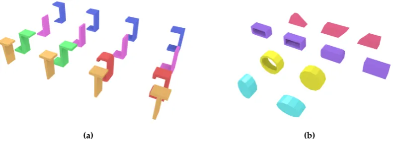
• Primitive instancing:an object is represented based on a set number of predefined parameters. IFC uses this paradigm to define various forms of 2D profiles (Figure2), as well as volumetric objects such as spheres, cones and pyramids.
• CSG and Boolean operations:an object is represented as a tree of Boolean set operations (union, intersection and difference) of volumetric objects (see?] for more details). Half-spaces are often used to cut out the undesired parts of surfaces or volumes.
• Sweep volumes:a solid can also be defined by a 2D profile (a circle, a rectangle or an arbitrary polygon with or without holes) and a curve [?] along which the surface is extruded.
• B-rep:an object is represented by its bounding surfaces, either triangulated meshes, polygonal meshes or topological arrangements of free-form surfaces.
2.2. Previous GIS-BIM integration efforts
The integration of BIM and GIS data is a complex topic that has been tackled in different ways. As?] state, the integration can involve semantics and/or geometry, and it can involve the conversion of BIM and GIS data to either a unified model or to the standards of each other (either bidirectional or only one-way). In the GeoBIM project, we instead focused on realising the integration in practice and at thedatalevel. By contrast,?] discusses how the integration can also be performed at theprocessand applicationlevels.
Most of the related work on this topic is concerned with converting IFC models to a GIS model like CityGML because that implies simplifying and removing details and extraneous information in
(a) (b)
Figure 2. IFC defines various types of parametric curved profiles such as (a) those based on the characters U, L, Z, C and T and (b) those based on trapezia, (rounded) rectangles, circles with/without holes and ellipses. Note the various types of tapered and curved parts of the profiles. These are most commonly used in extrusions such as those shown here.
the data. The inverse operation, from GIS data to BIM, is rarely discussed as it is deemed less useful and it might involve adding more details to the data. Nonetheless, there are methods to create BIM from existing models, which can be considered as GIS to BIM; see?] for an overview. One use case for the conversion from GIS to BIM is to be able to import GIS data about the environment into BIM software so that designers can consider the environment in their design. An example is converting data about the geological subsurface (defined in GIS formats) into IFC [?].
?] and?] propose to combine information from both domains and create a unified model in which all the semantic properties of IFC and CityGML are present, and they propose using bidirectional mappings for all the semantic classes relevant to IFC and CityGML. However, they extract the geometries separately from the two models and need manual editing to enrich the result. The resulting unified model does not acknowledge the particularities of the two different communities, and their focus is mostly LOD4 since all the features are mapped to LOD4.?] extends the data model of GML (and not CityGML) to create a unified model supporting two specific applications (visualisation and flood damage assessment to specific buildings).
A few programs offer the possibility to convert IFC models into CityGML models. Three examples are: the Building Information Modelserver5, IfcExplorer6 and Safe FME7. All of them allow the users to convert IFC models to CityGML at different LODs. The users can in some cases choose which IFC objects should be used. However, all the features are converted, without any selection or post-processing to keep only the relevant ones. Different projects use such approach to obtain integrated datasets useful for visualisation-based analysis, e.g.?]. Observe here that for visualisation and other applications, such as daylight simulation, converting all the geometries is not a major hindrance since internal elements will not displayed or will not affect the end result. The size of the dataset will however increase and slow down the visualisation process.
?] built an open-source web-GIS in which IFC objects can be imported after having been converted to b-rep models. Unfortunately, only sweep-volume objects can be converted and all the geometries are kept (thus resulting in non-manifold building models).?] developed an CityGML ADE (application domain extension) called GeoBIM8, so that new semantic classes defined in IFC are added in a CityGML model. However, no geometric manipulation is performed.
There have been different attempts at converting IFC models to CityGML LOD2/3 models by processing the geometries.?] describe the general steps needed to convert an IFC file to an alternative data model closely related to CityGML (the QUASY model). They first map the semantics from IFC to QUASY and select the relevant boundary objects, and then the outer visible surfaces are extracted by selecting a subset of the input objects. For the (equivalent of) the LOD3 model, they discard geometries inside the building by projecting each floor of a building to horizontal and vertical ‘footprints’ and keeping only those touching the envelope. This technique may yield building models having holes/gaps in the exterior envelope. Moreover, while the output models appear to be LOD3 models, the walls and the roof are volumetric. ? ] converts IFC to the different LODs of CityGML. To obtain the exterior envelope of each building, they use a ray-tracing algorithm: they define a few points-of-view and determine whether a given surface is visible from them. If so, it is assumed to form part of the exterior boundary. This method will however yield buildings with several holes as several surfaces (e.g. those for a roof overhang, or small ones near a window sill) will not be visible from the finite set of points of view.?] convert IFC models to LOD3 models by selecting a subset of the objects and then extracting the exterior envelope by using a series of Boolean set operations in 3D. Their algorithm does not yield holes/gaps if the input does not contain any and they can close small gaps by buffering all primitives; this however introduces artefacts in the entire model. In addition, in their implementation the semantics of the objects cannot be stored and thus different tricks are used to recover it for each surface in the final model.
Recently, the Open Geospatial Consortium carried out research on the use of IFC and CityGML in Urban Planning [?]. This project was done in the context of the Future City Pilot Phase 1. Their main conclusions align to the findings we present in this paper. They firstly conclude that the architecture design processes often do not require georeferencing, and unreferenced architectural models seriously hinder their reuse in GIS environments. Instead, for IFC data to be of use in GIS applications, the geographical coordinate system of IFC file should be set in advance. Secondly, the OGC project identified several inconsistencies in coding IFC elements in practice that made transformation to CityGML complicated. Therefore they conclude that for adopting IFC in urban planning a clear set of specifications needs to be set for the preparation of IFC files. This is line with our findings (see further). However, we go one step further and actually propose such guidelines from our findings in Section3.3.
5 http://bimserver.org
6 http://iai-typo3.iai.fzk.de/www-extern/index.php?id=1566&L=1 7 http://www.safe.com
3. Automatically processing complex architectural models in IFC
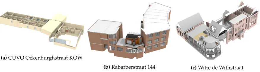
The first part of the GeoBIM project was an experiment- and use case-driven scoping study with two aims: (i) to develop a CityGML/IFC interface for reusing GIS data in the BIM domain and vice versa, and (ii) to formulate recommendations for further integration, such as modelling guidelines for bidirectional integration based on the main issues identified and the preferred solutions to these. For this part of the GeoBIM project, we focused our experiments on three IFC files provided by the city of the Hague (Figure3). These are complex models with several thousand objects each and which use all the main representation paradigms that are possible in IFC (see Section2.1.2).
(a)CUVO Ockenburghstraat KOW
(b)Rabarberstraat 144 (c)Witte de Withstraat
Figure 3.Test IFC files from the City of The Hague
3.1. Initial methodology
Initially, as shown in Figure4, our initial workflow was based on the use of two well-known and used open-source libraries: CGAL9and IfcOpenShell10. We attempted to parse and process every object in an IFC file independently using a modified version of IfcOpenShell, where we substituted its Open CASCADE11-based kernel for a new one based on CGAL. The aim of this approach was to use spatial analysis algorithms from the GIS domain and the robust Boolean set operations on Nef polyhedra available in CGAL in order to solve various use cases [? ? ?]. We chose for this approach since our previous experience showed that the Boolean set operations in Open CASCADE are not as robust as those available in CGAL. For instance, compliance with height regulations in 3D zoning maps can be checked with CGAL using Boolean intersections of the model and the polyhedra generated from zoning maps.
Geometric operations
Ifc input
Parsing and I/O
Conversion and use cases
Figure 4.The initial methodology
The main geometric IFC entity types were thus converted into appropriate CGAL-based representations for points, polygonal curves, polygons with holes, planes, etc. In this process,
9 The Computational Geometry Algorithms Library:https://www.cgal.org/ 10 http://ifcopenshell.org
implicit and parametric curves, surfaces and volumes were interpreted into explicit boundary representations and discretised into polygonal curves and polygonal meshes (Figure2). All placements and transformations in IFC are converted into 3D affine transformations defined by a matrix, which can then be recursively applied to each object as necessary. In this manner, we obtained a polyhedral representation of every volumetric object and store it as a CGALPolyhedron_3.
Some geometric IFC entity types however required additional processing, such as the CSG solid, half-space and Boolean result representations which are obtained by first converting a polyhedron to a CGALNef_polyhedron_3and then performing Boolean set union, intersection or difference operations.
This methodology yielded good initial results (Figure5), being able to parse and generate CGAL geometries for a rapidly increasing number of the objects present in our test IFC models.
(a)CUVO Ockenburghstraat KOW
(b)Rabarberstraat 144 (c)Witte de Withstraat
Figure 5.Test IFC files from the City of The Hague after processing with initial methodology
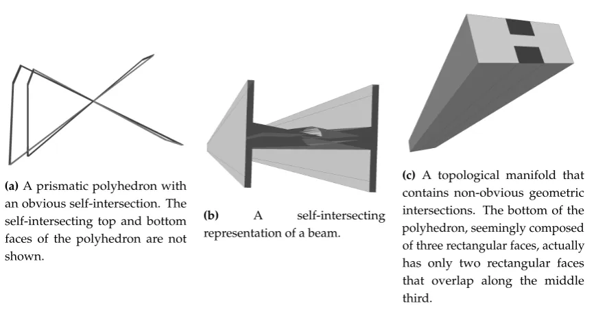
However, we found that invalid objects are widespread in the IFC models we received as part of this study—something that is consistent with our previous experience with BIM and GIS data and with the experience of other practitioners we spoke to; see for instance? ]. Self-intersections and intersections between objects were the most common errors (Figures6aand6b), but there were also uneven surfaces that were supposed to be planar and disconnected objects that were modelled as one. One of the most interesting errors we found was the presence of several objects that are seemingly valid and form topological 2-manifolds (as checked by making sure that surfaces join in pairs along common edges), but in reality contain self-intersections (Figure6c). Note that this is something explicitly disallowed by the IFC standard12, but not enforced by most current implementations.
After asking the architects producing these models, we found that such errors are generated by the software they work with. They are mostly unaware of these errors, or at least these do not significantly hinder their design, building and constructions processes.
Since invalid objects would often cause our processing methods to crash, we attempted to catch and correct as many errors as possible, and so we added a series of validation tests on every object and to its openings (if any). These are done at appropriate places during the construction of every object, before the conversion of a CGALPolyhedron_3to aNef_polyhedron_3, and before it is triangulated for the generation of a file used for visualisation (the simple OBJ format). Among others, we tested for:
• combinatorial validity (2-manifoldness),
• surfaces that enclose a space,
• crashes/failures of CGAL’s triangulation algorithm (e.g. when a surface self-intersects),
• self-intersections,
• CGAL crashes/failures when converting to aNef_polyhedron_3.
12 http://www.buildingsmart-tech.org/ifc/IFC2x3/TC1/html/ifcgeometricmodelresource/lexical/
(a)A prismatic polyhedron with an obvious self-intersection. The self-intersecting top and bottom faces of the polyhedron are not shown.
(b) A self-intersecting representation of a beam.
(c) A topological manifold that contains non-obvious geometric intersections. The bottom of the polyhedron, seemingly composed of three rectangular faces, actually has only two rectangular faces that overlap along the middle third.
Figure 6.Some of the errors present in the test IFC files
In order to make sure that every face is planar, we also triangulated the faces of every object whenever we needed to create a Nef polyhedron. This ensured that the conversion from a CGAL Polyhedron_3to aNef_polyhedron_3is able to compute a plane passing through every face. Another possibility would have been to compute the best fitting plane per face and then snap a vertex to the intersection of the planes of its incident faces [?].
As CGAL and the typical prevalent geospatial databases only support polyhedra, an issue we identified is the potential for different results in the generation of discrete and explicit b-rep linear geometries (e.g. polygons and polygonal meshes) from the implicit and curved geometries in IFC. Explicit geometries will invariably yield different b-rep representations according to the chosen discretisation method and its parameters. For instance, we chose to discretise ellipses into closed polygonal curves using a customisable number of equal-angle intervals, and we chose to discretise spheres into icosahedral approximations with a customisable number of refinements. However, alternative methods could involve discretising ellipses using equal-length line segments and spheres using equal angle rectangular patches.
From a more practical standpoint, we also found that the available features of CGAL are not sufficient to comfortably model all the complex features of IFC—something that is also true for many other geometric processing libraries. For instance, CGAL Nef polyhedra do have support for half-space representations as long as an extended kernel is used, which incorporates polynomial representations of various classes such as planes. However, extended CGAL kernels appear to be incompatible with various parts of the Polygon mesh processing package, which we use for triangle-triangle intersection tests, 2-manifoldness tests, stitching the faces of a polyhedron together, and reversing normals, among other functions. Another example is that Nef polyhedra do not offer an efficient way to construct meshes that do not enclose a volume or to create aPolyhedron_3from such a mesh stored in a Nef polyhedron. While we have found (and partly implemented) workarounds around these CGAL problems, these involve very complex code, are too slow for practical use or do not cover all the many cases commonly present in IFC files.
the many errors that we found in the IFC models were unexpected, and therefore solving these was outside the scope of the project.
3.2. Final methodology
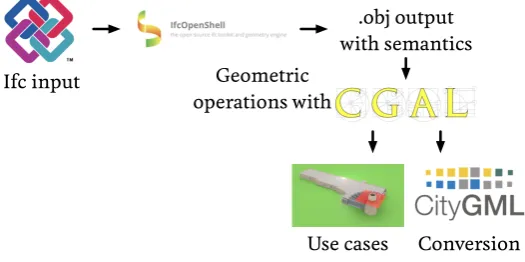
After running against the time constraints for the project, and due to the unsolvable issues identified with the initial methodology, we applied a simplified process that minimised the complex interaction between CGAL and IfcOpenShell (Figure7). The idea was to sidestep the limitations of CGAL in representing certain geometries and avoid many of the CGAL crashes caused by the interplay between invalid geometries in the IFC files and the stricter geometry requirements of CGAL compared to Open CASCADE.
.obj output with semantics Ifc input Geometric
operations with
Use cases Conversion
Figure 7.The final methodology
In this final methodology, we wrote a script that used the standard version of IfcOpenShell (with its Open CASCADE kernel) to export a series of Wavefront .obj files containing all relevant objects present in the IFC files. For this, we mainly looked at the subtypes of IfcBuildingElement, which according to the IFC standard define a ‘major functional part of a building’, those being: IfcBeam, IfcBuildingElementComponent, IfcBuildingElementProxy, IfcChimney,IfcColumn,IfcCovering,IfcCurtainWall,IfcDoor,IfcFooting,IfcMember,IfcPile, IfcPlate,IfcRailing, IfcRamp,IfcRampFlight,IfcRoof,IfcShadingDevice,IfcSlab,IfcStair, IfcStairFlight,IfcWall,IfcWindow. Thus, all geometries in every IFC file were extracted to an easily-parsable format while preserving the most relevant semantic information present in the original input file. This allowed us to overcome a shortcoming of the methodology of?].
Afterwards, we created a different program that parsed the individual .obj files and created a CGAL Nef polyhedron for every object. The parsed objects were processed using the same defensive programming methods and validation tests described for the initial methodology. The obtained Nef polyhedra were then selectively processed together using Boolean set operations so as to obtain a single Nef polyhedron containing all of the relevant parts of a building for a given spatial analysis.
The simplified processing pipeline in the final methodology resulted in a more workable methodology for the time frame of our project. All objects in our three test IFC datasets were able to be exported correctly to .obj and appeared to be visually correct. Moreover, many of the problems present in the IFC files could indeed be sidestepped by using the Open CASCADE kernel of IfcOpenShell, resulting in a significantly smaller number of problematic objects (e.g. such as a very complex staircase with many self-intersections), which could in general be disregarded for our purposes.
Similarly, small gaps between objects that would cause the interiors of a space (e.g. a room) not to be enclosed could be fixed by applying a Minkowski sum with a small kernel of a width equivalent to a snapping threshold between adjoining volumes. As another example, some CGAL crashes could be avoided by applying an iterative process where program crashes are caught, and an object that otherwise causes a crash is processed by applying a Minkowski sum with a small kernel until the object can be handled properly. These kinds of automated shape healing is what constitutes the advantage of using CGAL as an arbitrary-precision and robust geometry engine over the floating-point accuracy precision of Open CASCADE.
Unfortunately, even as we managed to process significantly more objects using the final methodology, we were still not able to fix all outstanding issues in the time allotted for the project, and thus some objects in the IFC files were necessarily discarded. This is a problem, since the automated tests we considered (e.g. zoning and shadow casting) cannot yield authoritative results if the models have missing objects, i.e. a lack of errors does not guarantee that a model passes a test with absolute certainty. Similarly, meaningful conversions from IFC to CityGML cannot be performed when spaces that should be well enclosed are not, due to missing objects at their boundaries.
3.3. A proposed set of IFC modelling guidelines
The development process of the two methodologies pointed to a series of issues that are common in IFC files, including in the files we received for this project. We thus looked further into these issues and produced a set of guidelines to avoid them. If properly followed, they would greatly simplify the automated processing of IFC files.
However, it is first important to note that many rules and recommendations regarding the proper use of IFC are already given in the IFC standard13, implementation guidance14, implementers guide for IFC2x315, implementer agreements16, and external guidelines such as BIM Basic IDM17. These range from fundamental aspects, such as how each IFC entity is defined and the possible values for each attribute, to common-sense practical rules, such as schemes for the consistent naming of objects. While the above mentioned sources already discuss plenty of guidelines on the proper use of IFC, during the course of this project and based on previous experiences, we have found that these sources of rules and recommendations are not always followed in practice, either because the authoring tool does not enforce or enable such rules, or because its users are unaware of certain issue. Moreover, they do not cover certain desirable aspects, resulting in a series of issues that make processing IFC models less than ideal. We therefore propose a series of recommendations that aim to improve their reusability in GIS applications:
Georeferencing IFC files should contain their precise real-world location using the latitude, longitude and altitude values in the IfcSite taking into account the offset given by the WorldCoordinateSystemof theIfcGeometricRepresentationContextfor the 3D model and the 2D plan (if used). Due to practical difficulties, it cannot be expected that these values match the reality with thePrecisiongiven in theIfcGeometricRepresentationContext, but the values should be easy to set to within a few meters of the real location. In addition, if the y-axis of the WorldCoordinateSystem in theIfcGeometricRepresentationContextdoes not match the true North direction, theTrueNorthattribute should be set as well. See Section5for more details on how these values are stored.
13 http://www.buildingsmart-tech.org/ifc/IFC4/final/html/
14 http://www.buildingsmart-tech.org/implementation/ifc4-implementation
15 http://www.buildingsmart-tech.org/downloads/accompanying-documents/guidelines/IFC2xModelImplementationGuideV2-0b.pdf
Valid volumetric objects Use volumetric objects as much as possible (e.g. sweeps and geometric primitives), test that they conform to their entity definition and take care to make sure these are watertight when using boundary representations.
No intersections There should be no self-intersections or intersections between objects, much like the BIM Basic IDM disallows intersections between objects by stating: ‘There are no duplicates or intersections permitted. Make sure this is checked in IFC.’ Among others, the Solibri Model Checker18and the simplebim Space Boundary add-on19are able to detect overlapping objects. Forming enclosed spaces that are also modelled as IfcSpaces The necessary objects so as to form
enclosed spaces should be modelled, and these objects should fit properly with each other and without gaps between them. In addition, we recommend that enclosed spaces are also modelled explicitly and with their precise geometry asIfcSpaces. Simpler applications that make straightforward use of theseIfcSpacescan then avoid more complex geometry processing. Using specific entities Always use the most specific entity type possible, avoiding generic types such asIfcBuildingElementProxy, use these specific entity types consistently across all objects of a model, and ensure that all related geometries of an object are marked as such. Additionally, when conversions to CityGML are concerned, it is worth focusing on entities that have a direct mapping to CityGML classes, such asIfcSlab.
4. Integrating subsurface information with IFC
Data about the subsurface is critical for any project involving shallow or deep digging of the ground, such as the construction of buildings and infrastructure. By taking into account such information at the design stage, the risks of accidents can be better handled and costs can be reduced significantly because safety and risk analysis can be based on data about the subsurface constitution. The Netherlands possesses a wide range of datasets about the subsurface that could be used for this purpose, and most of them are open data. In particular, the Netherlands Organisation for Applied Scientific Research (TNO), through the Geological Survey of the Netherlands (GDN), has made available the largest databank of the ground beneath the Netherlands. This databank, known by the acronym DINO20, is the single clearinghouse for data on the shallow and deep geology of the Netherlands. It comprises borehole data, groundwater data, cone penetration test data, vertical electrical soundings, the results of geological, chemical and mechanical sample analyses, borehole logs and seismic data.
However, despite the availability of subsurface data in the Netherlands as open data for years, the data is rarely used in the design and planning phase of major infrastructure projects. This might be due to the fact that the teams involved in those projects are not aware of the availability of such data, or could also be explained by incompatibilities between the formats in which the data is encoded and delivered by TNO and the tools that are used by designers of infrastructure projects.
4.1. Aim and scope of this subproject
A Dutch registry of subsurface information known as the BRO (Basis Registratie Ondergrond)21is currently being developed. The aim of the BRO is that subsurface information can easily be used in applications that can benefit from this data. To provide input for optimal development of the BRO, the project presented in this report examined how information about the geological subsurface can be made more accessible to designers and constructors, such that the BRO can be developed accordingly.
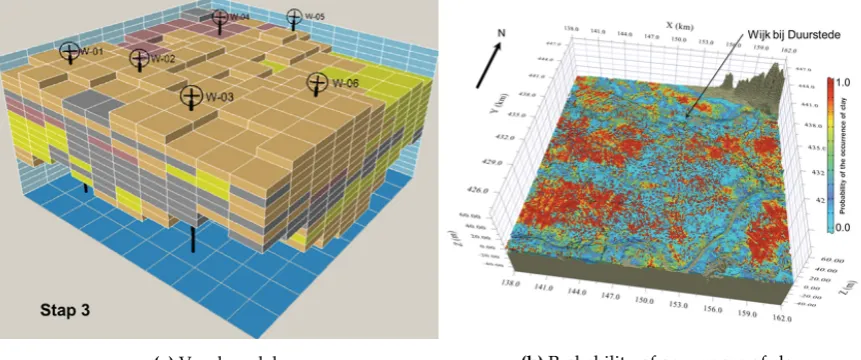
The subsurface data that is investigated here is GeoTOP (Figure8), a countrywide dataset on the geological composition of the shallow subsurface (maximum 50 meters below the ground surface),
18 https://www.solibri.com/faq/using-the-space-validation-rule-to-ensure-model-accuracy/ 19 http://datacubist.com/support/addon-spaceboundary.html
20 https://www.dinoloket.nl
which is disseminated under the NetCDF (Network Common Data Form) format and available online. GeoTOP divides the subsurface in millions of voxels of 100×100×0.5 m. Every voxel has properties assigned to it which characterize the physical and chemical properties of the soil, such as the lithographical unity and class.
On the design side, we focused on BIM projects, as well as the tools (software) used to design these projects. The aim in particular was to develop an interface between GeoTOP and construction/design applications, so that the latter can easily check and eventually integrate such data to their workflow. The focus is put as much as possible on solutions based on open standards to maximize the interoperability possibilities. However, tailored commercial solutions are also acceptable if they improve the usability of the data, but these should be developed upon open standards.
(a)Voxel model. (b)Probability of occurrence of clay.
Figure 8.GeoTOP data is encoded based on a voxel model with a resolution of 100×100×0.5 m. Each voxel in the model contains information on the lithostratigraphy and lithological classes, including the probability of occurrence for each lithological class (the values are based on interpolations of data from boreholes).
In addition to a prototype of the interface, this subproject aimed to also understand how the surface data can be accessed the best in the design phase and what next steps are needed to achieve this. We formulated some recommendations in the form of action points that can be addressed in a follow up project.
4.2. Our solution
In order to make open subsurface data such as GeoTOP readily available in designing tools, we opt for the development of an interface able to translate the GeoTOP data into IFC data in order to make it understandable for the BIM software products. Figure9illustrates the workflow of our approach.
Since subsurface information is not the focus of IFC, there is no class directly suitable for the representation of such data. It is however possible to bypass such a limitation by relying on a class that is meant to represent generic spaces known as theIfcSpaceclass and which can easily represent the voxel structure of GeoTOP.
We entirely relied on open source tools to build our solution, which is implemented in C++. For parsing NetCDF data, we used the NetCDF C++ API22. To deal with IFC reading and writing, we relied on the IfcOpenShell library. Finally, we developed a simple viewer to visualize the extracted voxels, which relies on the libQGLViewer library23.
Based on discussion with the GeoTOP expert from TNO, we decided that our solution would store only the most important values from GeoTOP into the Description attribute ofIfcSpace. These are the GeoTOPstratandlithokclasses (Figure10).
Figure 10.Produced voxels from the GeoTOP underneath the Faculty of Architecture of the TU Delft (visualised on BIM Vision software).
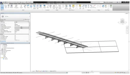
Although the implementation of the proposed solution could be achieved properly, several issues tend to make the integration between BIM and GIS data rather difficult. Among these, the most relevant was the problem of georeferencing the data from BIM or localising the GeoTOP inside a BIM platform (Figure11), which needed to be done manually.
4.3. Recommendations
From our experiments, we can conclude that technically it is possible to provide BIM practitioners with subsurface data. However, since using 3D GIS data in BIM software and vice versa is currently difficult, this is a topic that requires further attention. In order to guide this in the right direction, we formulated the following recommendations:
• Further investigation of practices of the BIM practitioners is needed regarding subsurface issues. To obtain initial understanding of how they use (or would like to use) subsurface data, we set up a small questionnaire which was distributed as part of the BIM-loket newsletter. The responses show that BIM practitioners are interested in subsurface data, but currently have difficulties
Figure 11.Attempting to put a BIM model of a bridge (provided by VolkerInfra for testing) and the generated GeoTOP voxel model.
using it. Also, it must be said that it was very hard to get the BIM community involved. In this project, we have also tried to organise a session for BIM vendors but there was little to no interest.
• It is necessary to develop more tools that are able to handle other types of subsurface data with more/different coverage.
• Discussions should be started between BIM and GIS practitioners for better handling of georeferencing/alignment practices and the establishment of guidelines to support this.
• It is desirable to investigate possible approaches to allow the automatic integration/alignments of the models in either BIM or GIS systems.
• Finally, the issues of integrating rough and fuzzy subsurface data with detailed objects represented in BIM that have a much higher accuracy should also be investigated. Most BIM sites fall within a complete voxel or a few voxels only, so it is worth considering what is the value of conclusions drawn from this data integration which may have severe impact on a risk analysis? This requires the close involvement of geological data experts.
5. Georeferencing IFC models
Properly georeferencing an IFC file makes it possible to link the (local) coordinates inside an IFC model with their corresponding real-world coordinates, and thus to place the model of a single building or construction within the virtual environment. From our discussions with other researchers and from the results of the previously presented two subprojects, it is clear that this is a major issue in practice.
equator, east of the zero meridian in IFC2x3, or west of the zero meridian in IFC4. These angles are expressed according to the typeIfcCompoundPlaneAngleMeasureand all components (i.e. degrees, minutes, seconds and millionth-seconds of arc) should have the same sign. According to the IFC standard, the geographic reference given might be the exact location of the origin of the local placement of theIfcSiteor it might be an approximate position for informational purposes only. The elevation is defined according to the datum elevation relative to sea level.
In addition,IfcSite contains a few other attributes that allow for an approximation of the real-world location to be given. TheLandTitleNumbercan store the designation of the site within a regional system (e.g. a cadastral record ID), and theSiteAddresscan store the postal address of the site. The IFC entityIfcGeometricRepresentationContextis used to define the coordinate space of an IFC model in 3D and optionally the 2D plan of such a model. This entity can be used to offset the project coordinate system from the global point of origin using theWorldCoordinateSystemattribute, it defines thePrecisionunder which two given points are still assumed to be identical, and it defines the direction of theTrueNorthrelative to the underlying coordinate system. The latter attribute defaults to the positive direction of the y-axis of theWorldCoordinateSystem.
In theory, the use of the latitude, longitude and altitude values in theIfcSitewith an optional offset and true North direction given by theIfcGeometricRepresentationContext, should make it possible to precisely georeference an IFC model. In fact, in our experience most IFC files do fill in the requisite values in theIfcSite. However, these values are almost always set to zero, to a default or wrong location, or to a very rough approximation of the real location (e.g. a point in the same city). This is unfortunately compounded by the mismatched definitions of the positive direction for the longitude in IFC2x3 and IFC4.
5.1. Adding georeferencing information in Revit 2018
The georeferencing information that is found in an IFC file depends on the BIM software from which it was exported. Since for many users this means Autodesk Revit, we briefly describe how it can be set in this software, where there is a set of relevant functions made available for designers to incorporate georeferencing information in their models within theManagetab (Figure12a).
While theCoordinatesandPositionbuttons are related to the local coordinate reference system of Revit, which only indirectly affect the georeferencing of the model, theLocationbutton allows the user to directly link it to real-world coordinates. The location can be defined in three different ways: (i) using theInternet Mapping Serviceoption and clicking in a map window or using the address of the project (Figure12b), (ii) by choosing a city for a rough location (Figure12c), or (iii) by manually specifying a latitude and longitude.
By default, the project’s location is set to a place in Boston, USA, with a latitude value of 42.3584◦ and a longitude of−71.0597◦. For this reason, any IFC model exported from Revit and in which no project location has been specified will be georeferenced at that location. Among our test files, this is the case for the Witte de Withstraat model, which is supposed to be located in the Hague, but which contains the default location coordinates of Revit (Figure13).
(a)Available tools
(b)Map-based (c)City-based
Figure 12. Tools to select a project’s location in Revit 2018.
Figure 13.Wrong georeferencing of the Witte de Withstraat model.
(a)Making the base and survey points visible in Revit.
(b)Project Base Point
(c)Survey Point
5.2. Example: correction of the georeferencing of the Witte de Withstraat model using Revit
As discussed previously, we received the Witte de Withstraat model with the default georeferencing from Revit, i.e. located in Boston and with its true North set to the y-axis. Firstly, the latitude and longitude can be specified quite easily with theLocationtool using the Internet Mapping Service option (Figure15a). Note that the new latitude and longitude are inserted in the IfcSiteattributes (Figure15b), but the elevation is kept at 0.0 (which is not really a problem for this model in the Netherlands).
(a)Setting in correct location in the Internet Mapping Service tool.
(b)The new coordinates in the IFC file.
Figure 15.Correcting the location of the Witte de Withstraat model.
Afterwards, correcting the model’s true North requires the angle difference between the project North and the true North. As it is possible to import images in Revit, we relied on a simple screenshot of the satellite image of the real location, with the building properly oriented with respect to the true North (Figure16).
By roughly finding on the image the point that corresponds to the project base point as well as the survey point in the case of our test model, it is possible to visually recognize the corresponding line of the project North. Then it is necessary to determine the angle between that line and the geographic North one. This can be done by drawing two lines corresponding to those directions (Figure17a). The measuring tools of Revit then allow the user to compute the angle, which is 127◦and corresponds to the angle from the green line to the orange line in the counter-clockwise direction. The correct value of the angle to the true North from the project North is thus equal to 360−127=233◦, which is then entered in theAngle to True Northattribute of theProject Base Point(Figure17b).
Figure 16. A screenshot from Google Maps is used to identify the orientation of the building with respect to the true North. The green circles indicate the project base and survey points.
(a) Finding of the angle between the true north (green line) and the project north (orange).
(b) Correction of the Project Base Point’s True North attribute.
5.3. IfcLocator: an open-source web service for georeferencing IFC models
The above mentioned process requires the use of Revit, and thus limits who can correct the georeferencing in an IFC file. For our project, we therefore developed theIfcLocator24, a supporting tool that allows the user to view and check the location of the project stored in an IFC file and to correct that information when necessary. The tool is based on Cesium25, which is an open source Javascript library for 3D mapping, including an intuitive 3D viewer of the globe. The choice of a web-based Javascript open source code was motivated by the high flexibility offered by such approach, which is cross-platform. Furthermore, the users can perform all the operation locally, which means they do not have to send their model to a remote server.
(a) Superposed floor plan and image oriented with
respect to the true North (b) Superposed floor plan and image oriented with respect to the project North
(c)NewIfcDirectionof the true north.
(d)NewSurvey Pointof the project
6. Conclusions
This paper presents our research project that aims at improving the reuse of BIM data in geo applications and vice versa. Based on the results of the project, it can be concluded that a full integration of GIS and BIM data is far from straightforward given current practice. This is partly because existing BIM models contain many geometrical and topological errors which need to be properly handled and
often fixed before a conversion or automated processing can be successful. It should be observed that these may not be problematic when used in a BIM environment because of a few reasons:
1. many more geometry types are usually natively supported in BIM software than in GIS software; 2. geometric errors (e.g. self-intersections) are often found in places that are inconspicuous or
invisible from the outside;
3. data is often only used for visualisation purposes, which does not require geometric and topological correctness;
4. or the errors only show after the implicit and parametrised types have been converted into explicit geometries (which is during the conversion to IFC).
However, these errors are very problematic in many applications that involve the automated processing of IFC data, such as in GIS operations that perform spatial analyses, which often involve complex operations such as Boolean set operations. Therefore, functionalities to validate the geometry of a BIM model are required; see?] for an equivalent for 3D GIS datasets.
Another conclusion that can be drawn is that it is unrealistic to develop a robust process for all IFC geometry entity types, particularly so for independent developers and smaller vendors. In our experiments, we have so far developed a solution for only a subset of the IFC standard. It would take years to extend our efforts to cover all entities, while in practice many of them are rarely used. With IFC, there are many different ways to model an object, which hinders the adoption of the standard and standardisation in the community. Ideally, standards that are intended for exchange should define only one way to model something—this both fosters data exchange and makes it easy to create compliant implementations of the standard. Therefore we recommend to formulate and agree on guidelines to standardise the way a specific situation should be modelled in IFC.
Data exchange and its accompanying problems has a much longer history in the GIS domain than in the BIM domain. As also concluded by?] from?], the relatively younger concept of BIM and its standard IFC have not satisfied the requirements of standards yet: competitiveness, conformity, and connectivity. BIM has to further develop in this respect, including paying attention to formal definitions for correct geometries, adhering to these and developing functionality to validate models.
While many academic research has demonstrated successful IFC-CityGML transformations, they have mostly developed their own solution, based on the use case or data at hand. A transformation from IFC to CityGML that works in practice requires a standardised transformation as there are currently many different interpretations of how to best transform an IFC file into CityGML. From a geometric perspective, this diversity in transformation is mainly due to the many classes of IFC that need to be converted into the relatively few classes of CityGML. The processing needed to make explicit geometries from implicit geometries and to change geometry classes (like conversion of volumes in IFC into surfaces in CityGML for walls) can result in different outcomes in different implementations. For a sustainable information chain that supports the life cycle of objects, this is unwanted, and therefore there is a need to define one uniform and standardised transformation.
From our experiments we can also conclude that additional information for building modellers is needed in order to support a better automated processing pipeline for IFC geometries in a GIS environment. We believe that our guidelines are a good first step in this direction, which should help to create CityGML/GIS-ready IFC datasets. However, additional efforts are needed since the export process from other BIM formats to IFC is rather opaque and the implementation of the guidelines is not straightforward.
More understanding is also needed in order to find out how BIM data are used in GIS applications and vice versa. For example, how are IFC designs checked against the existing physical world and against a 3D zoning plan (both GIS data). Is this done in BIM software?, and thus GIS data needs to be imported and localised in BIM software; or is this done in GIS software?, and thus BIM design data needs to be imported in GIS software and properly georeferenced.
version of the BIM model (with relevant attributes for the GIS world) will be converted into a GIS model. A 3D city model may serve as a connection between the two, with unique identifiers and update mechanisms in order to keep the separated BIM models consistent with their generalised counterparts.
Author Contributions:Conceptualization, Ken Arroyo Ohori, Hugo Ledoux and Jantien Stoter; Data curation, Ken Arroyo Ohori, Abdoulaye Diakité and Thomas Krijnen; Formal analysis, Ken Arroyo Ohori, Abdoulaye Diakité and Thomas Krijnen; Funding acquisition, Jantien Stoter; Investigation, Ken Arroyo Ohori, Abdoulaye Diakité and Thomas Krijnen; Methodology, Ken Arroyo Ohori, Abdoulaye Diakité, Hugo Ledoux and Jantien Stoter; Project administration, Ken Arroyo Ohori and Jantien Stoter; Resources, Hugo Ledoux and Jantien Stoter; Software, Ken Arroyo Ohori, Abdoulaye Diakité and Thomas Krijnen; Supervision, Ken Arroyo Ohori and Jantien Stoter; Visualization, Ken Arroyo Ohori, Abdoulaye Diakité and Thomas Krijnen; Writing – original draft, Ken Arroyo Ohori and Abdoulaye Diakité; Writing – review & editing, Ken Arroyo Ohori, Abdoulaye Diakité, Thomas Krijnen, Hugo Ledoux and Jantien Stoter.
Funding:This project has received funding from the European Research Council (ERC) under the European Union’s Horizon 2020 research and innovation programme (grant agreement No 677312 UMnD). The subproject on the automated processing of complex architectural IFC models received funding from a collaboration of Rijkswaterstaat, the cities of The Hague and Rotterdam, Kadaster, Geonovum, and BIM-loket. The subproject on the integration of information about the geological constitution of the subsurface at the design stage was partly funded by the former Ministry of Infrastructure and Environment of the Netherlands.
![Figure 1. A building represented in LOD0 to LOD4 (image from ? ]).](https://thumb-us.123doks.com/thumbv2/123dok_us/7921783.1315362/4.595.80.513.86.204/figure-building-represented-lod-lod-image.webp)