Design and Analysis of Extended Surfaces
with Different Thermal Conductivity Using
ANSYS 12
Ankit Mayank 1, Rajvinder Singh 2, J.P. Singh 3, Ashok Singh Yadav 4
U.G. Student, Department of Mechanical Engineering, AIT Rampur, Uttar Pradesh, India 1,2
P.G. Student, Department of Mechanical Engineering, RIT Roorkee, Uttarakhand, India 3
Asst. Professor, Department of Mechanical Engineering, AIT Rampur, Uttar Pradesh, India 4
ABSTRACT: The engine is the heart of any vehicle and heat is mainly generated in the engine. The cooling mechanism of any engine is mainly dependent on the design of the fin and fin material. Fins are used to increase the heat transfer rate of any surface. Generally aluminum alloy with thermal conductivity 235W/m-K is used as fin material in the bikes and our aim of the analysis is to study the different materials which can be used in fins and analyze the cooling rate by varying the heat flux accordingly. The model of rectangular fin is created and thermally analyzed with the help of ANSYS software which is FEA based. FEA divides (descretize) the structure (which is continuous otherwise) into small but finite, well defined, elastic substructure (element).
Element type SOLID87 which has tetrahedral 10 node structure is well suited to model irregular meshes (such as produced from various CAD/CAM systems). The element has one degree of freedom, temperature, at each node.
KEYWORDS: SOLID87, FEA, Descretize etc.
I. INTRODUCTION
has led to development and use of many techniques termed as “Heat transfer Augmentation”. This technique is also termed as “Heat transfer Enhancement” or “Intensification”. Augmentation techniques increase convective heat transfer by reducing the thermal resistance in a heat exchanger. Many heat augmentation techniques has been reviewed, these are (a) surface roughness, (b) plate baffle and wave baffle, (c) perforated baffle, (d) inclined baffle, (e) porous baffle, (f) corrugated channel, (g) twisted tape inserts, (h) discontinuous Crossed Ribs and Grooves. Most of these enhancement techniques are based on the baffle arrangement. Use of Heat transfer enhancement techniques lead to increase in heat transfer coefficient but at the cost of increase in pressure drop. B. Ramdas Pradip et. al. [6]. Extended Fins in the Optimization of Internal Combustion Engine they found for high speed vehicles thicker fins provide better efficiency. When fin thickness was increased, the reduced gap between the fins resulted in swirls being created which helped in increasing the heat transfer. Large number of fins with less thickness can be preferred in high speed vehicles than thick fins with less numbers as it helps inducing greater turbulence J .Ajay Paul, Sagar Chavan Vijay [7].
II. RELATEDWORK
Kumbhar D.G, Dr. N.K. Sane, Chavan S. T., et al (2009) [8]. In this paper, the effect of triangular perforations on rectangular fin is investigates the comparison of perforated fin with solid fin for temperature distribution along the fin and heat transfer rate. The analysis is done using software ANSYS and also by experimentation. The investigation observed that heat transfer rate increases as well as the same time reduce the cost of fin with perforations as compared to fins of similar dimensions without perforations. It concluded that heat transfer rate is different for different materials or heat transfer rate changes with change in thermal conductivity of the material.
Abdullah, H. Alessa et. al. [5] had studied the natural convection heat transfer enhancement from a horizontal rectangular fin embedded with equilateral triangular perforations. The heat dissipation rate from the perforated fin is compared to that of the equivalent solid one. They concluded that, For certain values of triangular dimensions, the perforated fin can result in higher heat transfer enhancement. The magnitude of enhancement is proportional to the fin thickness and its thermal conductivity.
[9] Shivdas S kharche et.al theoretically and experimentally cost analyzed the natural convection heat transfer from vertical rectangular fin arrays with and without notches at the center. They analyzed the notches of different geometrical shapes. After the experimental study they have concluded that the heat transfer rate in notch fins is more as compare to the un notched fins.
[10]. Mr. N.Phani Raja Rao, Mr. T. Vishnu Vardhan. “Thermal Analysis of Engine Cylinder Fins by varying its geometry And Material.”[12] .The principle implemented in the project to increase the heat dissipation rate by using the air. In present study, Aluminum alloy 6061 and magnesium alloy are used and compared with Aluminium Alloy A204. The various parameters (i.e., shape and geometry of the fin) are considered in the study, shape (Rectangular and Circular), thickness (3 mm and 2.5 mm). By reducing the thickness and also by changing the shape of the fin to circular shaped, the weight of the fin body reduces thereby increasing the heat transfer rate and efficiency of the fin. The weight of the fin body is also reduced when Magnesium alloy is used. The results shows, by using circular fin with material Aluminum Alloy 6061 is better since heat transfer rate, Efficiency and Effectiveness of the fin is more. By using circular fins the weight of the fin body reduces compare to existing engine cylinder.
III. EXPERIMENTALSETUPANDFINDESIGN
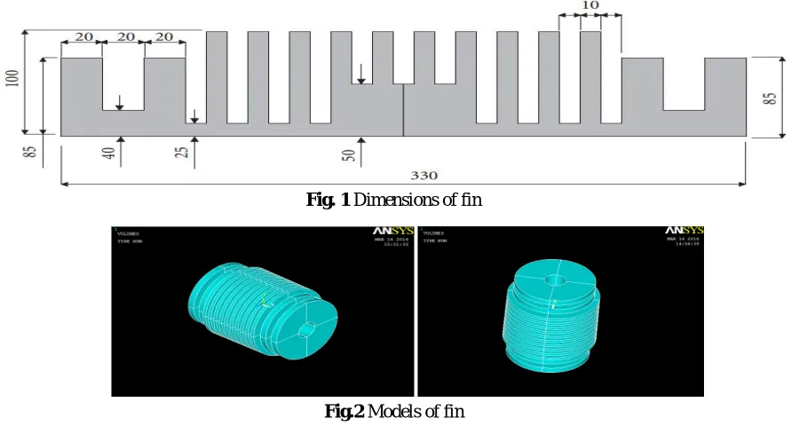
developed using ANSYS 12 .The dimensions for the fin shown in fin.1 In the present study surrounding temperature at 293 K.. Bottom surface of the fin is exposed to a variable heat flux of 600,800, 1000, 1200, 1400 W/m2.
Fig. 1 Dimensions of fin
Fig.2 Models of fin
It is, however a 2D model. The width of the fin is 100 mm and this dimension can be used to create 3D model. After that meshing of the fin can be carried out. The 3-D model is shown in fig.3 and fig-4 in different views.
IV. RESULT ANALYSIS
For thermal analysis of designed fin, different materials like aluminium (thermal conductivity 170 and 235 W/mK), stainless steel (thermal conductivity 14 W/mK and copper (thermal conductivity 398 W/mK) have been used in ANSYS 12. The result obtained for nodal temperature after varying the heat flux from 800 to 1200 at the interval of 200 was observed and shown below in the detail.
Case 1 Aluminum with thermal conductivity k= 170 W/mK.
Fig.3 Nodal temp at flux 800 Fig.4 Nodal temp at flux 1000 Fig.5 Nodal temp at heat flux 1200
Case 2 Copper with thermal conductivity k=398 W/mK.
Fig.6 Nodal temp.at flux 800 Fig.7 Nodal temp.at flux 1000 Fig.8 Nodal temp.at flux1200
Nodal temperature values at heat flux 800, 1000, 1200 for copper are 360.922, 377.902 and 394.883 respectively.
Case 3 Stainless steel with thermal conductivity k=14 W/mK.
Fig.9 Nodal temp.at flux 800 Fig.10 Nodal temp at flux 1000 Fig.11 Nodal temp at flux 1200
Nodal temperature values at heat flux 800, 1000, 1200 for stainless steel are 1879, 2275and 2672 respectively.
Case 4 Aluminum with thermal conductivity k=235 W/mK.
Fig12 Nodal temp at flux 800 Fig 13 Nodal temp at flux 1000 Fig.14 Nodal temp at flux 1200
V. ANALYTICALRESULTTABLE
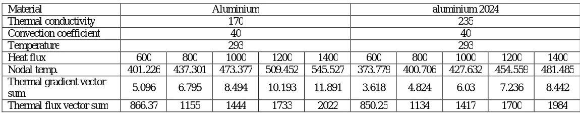
Table 1 & 2 show the values of thermal gradient vector sum, nodal temperature and thermal flux vector sum for different materials that has been considered in the present analysis.
TABLE 1: Variation of result at different values of heat flux for Aluminium and Aluminium 2024.
Material Aluminium aluminium 2024
Thermal conductivity 170 235
Convection coefficient 40 40
Temperature 293 293
Heat flux 600 800 1000 1200 1400 600 800 1000 1200 1400
Nodal temp. 401.226 437.301 473.377 509.452 545.527 373.779 400.706 427.632 454.559 481.485 Thermal gradient vector
sum 5.096 6.795 8.494 10.193 11.891 3.618 4.824 6.03 7.236 8.442
Thermal flux vector sum 866.37 1155 1444 1733 2022 850.25 1134 1417 1700 1984
TABLE 2: Variation of result at different values of heat flux for Copper and Stainless steel.
VI. CONCLUSION
Following conclusions are made on the basis of our analytical results:
1. It is concluded that when we change the material and heat flux, then heat transfer rate is increased.
2. If we increase the thermal conductivity of material then cooling rate of fin will be increased, which can be seen in nodal temp.
3. As thermal conductivity increases the nodal temperature reduces.
4. Fourier’s law states as the conductivity increases, heat transfer rate also increases which can be seen with our analysis (Copper with highest conductivity gives better heat transfer).
REFERENCES
[1] VS Daund, A Walunj and DD Palande, “Review of Natural Convective Heat Transfer from Rectangular Vertical Plate Fins “, International Journal of Advanced Technology in Engineering and Science, 2 (7), pp.294-304,2014 .
[2] Magarajan U, Thundil karuppa Raj R and Elango T, “Numerical Study on Heat Transfer of Internal Combustion Engine Cooling by Extended Fins Using CFD” , Research Journal of Recent Sciences, 1(6), pp.32-37,2012.
Material Copper stainless steel
Thermal conductivity 398 14
Thermal coefficient 40 40
Temperature 293 293
Heat flux 600 800 1000 1200 1400 600 800 1000 1200 1400
Nodal temp. 343.942 360.922 377.902 394.883 411.864 1484 1879 2275 2672 3068 Thermal gradient vector
sum 2.064 2.752 3.44 4.128 4.816 70.865 94.487 118.108 141.73 165.351
[3]. Guvenc A. and Yuncu H. “An experimental investigation on performance of fins on a vertical base in free convection heat transfer” Sprigler Verlag Heidelberg, Heat and Mass Transfer. pp.37: 409-416, 2001.
[4]. Leung C.W and Probert S.D. “Heat-exchanger performance: influence of gap width between consecutive vertical rectangular fin arrays” Applied Energy. pp.56: 1-8, 1997.
[5]. Abdullah, H. Alessa and Mohammed, Q. Al-Odat, “Enhancement of Natural Convection Heat Transfer from a Fin by Triangular Perforations of Bases Parallel and Toward its Base”, The Arabian Journal for Science and Engineering, vol. 34, pp. 531-544, 2009.
[6]. B. Ramdas, Pradip and K. Kumar, Dinesh, “A Study on the Heat Transfer Enhancement for Air Flow through a Duct with Various Rib Inserts”, International Journal of Latest Trends in Engineering and Technology, vol. 2, issue 4, pp. 479-485, 2013.
[7]. J.Ajay Paul, SagarChavan Vijay, Magarajan&R.Thundi lKaruppaRaj, “Experimental and Parametric Study of Extended Fins In The Optimization of Internal Combustion Engine Cooling Using CFD”, International Journal of Applied Research in Mechanical Engineering. [8] Kumbhar D.G., Dr. N K Saoe, Chavan S.T “ Finite Element Analysis and Experimental Study of Convective Heat Transfer Augmentation from Horizontal Rectangular Fin by Triangular Perforations”, Proc. of the International Conference on Advances in Mechanical Engineering, August 3-5,, pp. 376-380,2009.
[9] Shivdas S. Kharche, Hemant S. Farkade “Heat Transfer Analysis through Fin Array by Using Natural Convection”, International Journal of Emerging Technology and Advanced Engineering Website: www.ijetae.com (ISSN 2250 -2459, Volume 2, Issue 4, April 2012 [10]. Mr. N. Phani Raja Rao, Mr. T. Vishnu Vardhan. “Thermal Analysis Of Engine Cylinder Fins By Varying Its Geometry And Material.” International journal of Engineering Research & Technology.ISSN:2278-0181,Vol. 2 Issue 8, August(2013).
[11]M.P Shah,K.S Mehara ,S Gautam ,P Negi “Transient and Steady State Analysis of Fin Using FEM for Different Material “International journal for research in applied science and engineering technology (IJRASET) ISSN:2321-9653, Vol. 2 june 2014.