Design and Analysis of Different Material to Increase the
Performance of Ac Condenser
ABSTRACT
In systems involving heat transfer, a condenser is a device or unit used to condense a substance from its gaseous to its liquid state, typically by cooling it. In so doing, the latent heat is given up by the substance, and will transfer to the condenser coolant. Condensers are typically heat exchangers which have various designs and come in many sizes ranging from rather small to very large industrial-scale units used in plant processes. Air cooled condensers are used in small units like household refrigerators, deep freezers, water coolers, window conditioners, split
air-conditioners, small packaged
air-conditioners etc. These are used in plants where the cooling load is small and the total quantity of the refrigerant in the refrigeration cycle is small. Air cooled condensers are also called coil condensers as they are usually made of copper or aluminum coil.
Air cooled condensers occupy a
comparatively larger space than water cooled condensers.
In this thesis a design optimization technique that can be useful in assessing the best configuration of a finned-tube condenser. Heat transfer by convection in air cooled condensers is studied and improved in this work. The assessment has been carried out on an air-cooled finned-tube condenser of a
vapour compression cycle for air
conditioning system. Heat transfer analysis and CFD analysis is done on the condenser to evaluate the better design and material. The materials considered for tube is copper and for fins are Aluminum alloys 1100, 6063
and Magnesium alloy for different
refrigerants HCFC and 404R. 3D modeling is done in Pro/Engineer and analysis is done in Ansys. CFD analysis is done at different velocities. Theoretical calculations are done to determine heat transfer rate.
Dachepally Raghu Babu M.Tech (Thermal engineering),
P.G. Scholar Nishitha College of engineering and technology
Rangdal Srikanth Mtech(AMS), Asst professor
INTRODUCTION
Air Conditioner:
An air conditioner (often referred to as AC) is a home appliance, system, or mechanism designed to dehumidify and extract heat
from an area. The cooling is done using a simple refrigeration cycle. In construction, a complete system of heating, ventilation and air conditioning is referred to as "HVAC". Its purpose, in a building or an automobile, is to provide comfort during either hot or cold weather.
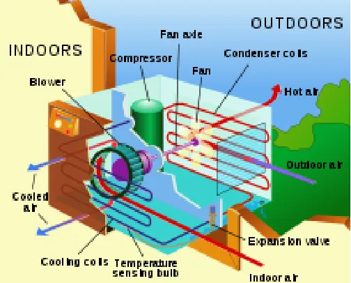
Figure 1: A typical home air conditioning unit
AIR CONDITIONING SYSTEM BASICS AND THEORIES
Figure 2: Refrigeration cycle
A simple stylized diagram of the refrigeration cycle: 1) condensing coil,
In the refrigeration cycle, a heat pump transfers heat from a lower-temperature heat source into a higher-temperature heat sink. Heat would naturally flow in the opposite direction. This is the most common type of air conditioning. A refrigerator works in much the same way, as it pumps the heat out of the interior and into the room in which it stands. This cycle takes advantage of the way phase changes work, where latent heat is released at a constant temperature during a liquid/gas phase change, and where varying the pressure of a pure substance also varies its condensation/boiling point. The most common refrigeration cycle uses an electric motor to drive a compressor. In an automobile, the compressor is driven by a belt over a pulley, the belt being driven by the engine's crankshaft (similar to the driving of the pulleys for the alternator, power steering, etc.). Whether in a car or building, both use electric fan
motors for air circulation. Since
evaporation occurs when heat is absorbed, and condensation occurs when heat is
released, air conditioners use a
compressor to cause pressure changes between two compartments, and actively condense and pump a refrigerant around. A refrigerant is pumped into the
evaporator coil, located in the
compartment to be cooled, where the low pressure causes the refrigerant to evaporate into a vapor, taking heat with it. At the opposite side of the cycle is the condenser, which is located outside of the cooled compartment, where the refrigerant vapor is compressed and forced through another heat exchange coil, condensing the refrigerant into a liquid, thus rejecting
the heat previously absorbed from the cooled space.
By placing the condenser (where the heat is rejected) inside a compartment, and the evaporator (which absorbs heat) in the ambient environment (such as outside), or merely running a normal air conditioner's refrigerant in the opposite direction, the overall effect is the opposite, and the compartment is heated. This is usually called a heat pump, and is capable of
heating a home to comfortable
temperatures (25 °C; 70 °F), even when the outside air is below the freezing point of water (0 °C; 32 °F). Cylinder unloaders are a method of load control used mainly in commercial air conditioning systems. On a semi-hermetic (or open) compressor, the heads can be fitted with unloaders which remove a portion of the load from the compressor so that it can run better when full cooling is not needed. Unloaders can be electrical or mechanical.
Refrigerants
"Freon" is a trade name for a family of haloalkane refrigerants manufactured by DuPont and other companies. These refrigerants were commonly used due to their superior stability and safety properties. However, these chlorine-bearing refrigerants reach the upper
atmosphere when they escape.[6] Once the
catalyst unless it binds with another chlorine radical, forming a stable molecule and breaking the chain reaction. The use of CFC as a refrigerant was once common, being used in the refrigerants R-11 and R-12. In most countries the manufacture and use of CFCs has been banned or severely restricted due to concerns about ozone depletion. In light of these environmental concerns, beginning on November 14, 1994, the Environmental Protection Agency has restricted the sale, possession and use of refrigerant to only licensed technicians, per Rules 608 and 609 of the EPA rules and regulations; failure to comply may result in criminal and civil sanctions. Newer and more environmentally-safe refrigerants such as HCFCs (R-22, used in most homes today) and HFCs (R-134a, used in most cars) have replaced most CFC use. HCFCs in turn are being phased out under the Montreal Protocol and replaced by hydro fluorocarbons (HFCs) such as R-410A, which lack chlorine. Carbon dioxide (R-744) is being rapidly adopted as a refrigerant in Europe and Japan. R-744 is an effective refrigerant with a global warming potential of 1. It must use higher compression to produce an equivalent cooling effect.
Types of air conditioner equipment
The external section of a typical single-room air conditioning unit. For ease of installation, these are frequently placed in a window. This one was installed through a hole cut in the wall. The internal section of the above unit. The front panel swings down to reveal the controls.
Window and through-wall units
Room air conditioners come in two forms: unitary and packaged terminal PTAC systems. Unitary systems, the common one room air conditioners, sit in a window or wall opening, with interior controls. Interior air is cooled as a fan blows it over the evaporator. On the exterior the air is heated as a second fan blows it over the condenser. In this process, heat is drawn from the room and discharged to the environment. A large house or building may have several such units, permitting each room be cooled separately. PTAC systems are also known as wall split air conditioning systems or ductless systems. These PTAC systems which are frequently used in hotels have two separate units (terminal packages), the evaporative unit on the interior and the condensing unit on the exterior, with tubing passing through the wall and connecting them. This minimizes the interior system footprint and allows each room to be adjusted independently. PTAC systems may be adapted to provide heating in cold weather, either directly by using an electric strip, gas or other heater, or by reversing the refrigerant flow to heat the interior and draw heat from the exterior air, converting the air conditioner into a heat pump. While room air conditioning provides maximum flexibility, when cooling many rooms it is generally more expensive than central air conditioning.
Evaporative coolers
comfort during hot weather. This type of cooler is the dominant cooler used in Iran, which has the largest number of these units of any country in the world, causing some to refer to these units as "Persian coolers." An evaporative cooler is a device that draws outside air through a wet pad, such as a large sponge soaked with water. The sensible heat of the incoming air, as measured by a dry bulb thermometer, is reduced. The total heat (sensible heat plus latent heat) of the entering air is unchanged. Some of the sensible heat of the entering air is converted to latent heat by the evaporation of water in the wet cooler pads. If the entering air is dry enough, the results can be quite comfortable; evaporative coolers tend to feel as if they are not working during times of high humidity, when there is not much dry air with which the coolers can work to make the air as cool as possible for dwelling occupants. Unlike air conditioners, evaporative coolers rely on the outside air to be channeled through cooler pads that cool the air before it reaches the inside of a house through its air duct system; this cooled outside air must be allowed to push the warmer air within the house out through an exhaust opening such as an open door or window.
These coolers cost less and are mechanically simple to understand and maintain.
An early type of cooler, using ice for a further effect, was patented by John Gorrie of Apalachicola, Florida in 1842. He used the device to cool the patients in his malariahospital.
Thermostats
Thermostats control the operation of HVAC systems, turning on the heating or cooling systems to bring the building to the set temperature. Typically the heating and cooling systems have separate control systems (even though they may share a thermostat) so that the temperature is only controlled "one-way." That is, in cold weather, a building that is too hot will not be cooled by the thermostat. Thermostats may also be incorporated into facility energy management systems in which the power utility customer may control the overall energy expenditure. In addition, a growing number of power utilities have made available a device which, when professionally installed, will control or limit the power to an HVAC system during peak use times in order to avoid necessitating the use of rolling blackouts. The customer is given a credit of some sort in exchange, so it is often to the advantage of the consumer to buy the most efficient thermostat possible.
Equipment capacity
Air conditioner equipment power in the U.S. is often described in terms of "tons of refrigeration". A "ton of refrigeration" is approximately equal to the cooling power of one short ton (2000 pounds or 907 kilograms) of ice melting in a 24-hour period. The value is defined as 12,000 BTU per hour, or 3517 watts. Residential central air systems are usually from 1 to 5 tons (3 to 20 kilowatts (kW)) in capacity.
electrical power grid in hot weather, when most units are operating under heavy load. In the aftermath of the 2003 North America blackout locals were asked to keep their air conditioning off. During peak demand, additional power plants must often be brought online, usually expensive peaker plants. A 1995
meta-analysis of various utility studies
concluded that the average air conditioner wasted 40% of the input energy. This energy is lost in the form of heat, which must be pumped out.
In an automobile, the A/C system will use around 5 horsepower (4 kW) of the engine's power.
unit size, BTU/h × hours per year, h × power cost, $/kW·h ÷ (SEER, BTU/W·h × 1000 W/kW)
(72,000 BTU/h) × (1000 h) × ($0.08/kW·h) ÷ [(10 BTU/W·h) × (1000 W/kW)] = $576.00 annual cost
A common misconception is that the SEER rating system also applies to heating systems. However, SEER ratings only apply to air conditioning.
Air conditioners (for cooling) and heat pumps (for heating) both work similarly in that heat is transferred or "pumped" from a cooler heat source to a warmer "heat sink". Air conditioners and heat pumps usually operate most effectively at temperatures around 10 to 13 degrees Celsius (°C) (50 to 55 degrees Fahrenheit (°F)). A balance point is reached when the heat source temperature falls below about 4 °C (40 °F), and the system is not able to pull any more heat from the heat source
(this point varies from heat pump to heat pump). Similarly, when the heat sink temperature rises to about 49 °C (120 °F), the system will operate less effectively, and will not be able to "push" out any more heat. Geothermal heat pumps do not have this problem of reaching a balance point because they use the ground as a heat source/heat sink and the ground's thermal inertia prevents it from becoming too cold or too warm when moving heat from or to it. The ground's temperature does not vary nearly as much over a year as that of the air above it.
SPECIFICATIONS OF CONDENSOR
The length and size of air conditioner condensers and evaporators have to be sized such that,
the refrigerant is completely
condensed before the
condenser’s exit, and
the refrigerant is completely
boiled before the
evaporator’s exit
Those two, depends mainly on the size of the compressor and refrigerant used. Air conditioner manufacturers has to understand how conduction, as well as convection works, to design an effective, yet compact air conditioner condenser and evaporator, per unit heat transferred. Normally, the condenser and evaporator will be designed to 110% of the intended heat transfer requirement, to cater for any performance drop during the service life.
Types of Condensers:
1) Evaporative Condenser
2) Air cooled condenser
3) Water cooled condenser
EVAPORATIVE CONDENSER:
Whereas a condenser/cooling tower arrangement requires a system of water distribution piping, this is almost entirely absent in the evaporative condenser. Only enough water need be circulated to ensure that the outside surface of the condenser coils is completely wet. The heat exchange is solely latent, and less water is required in circulation than is necessary with a condenser/cooling tower, where a sensible heat exchange occurs in the shell-and tube condenser. The evaporative condenser is thus more compact and is cheaper. It suffers from lack of flexibility, and oil return and other problems demand that the condenser should not be too far from the compressor. A cooling tower, on the other hand, may be a considerable distance away, the condenser then being adjacent to the compressor. Scaling on the tubes of an evaporative condenser may be something of a problem, particularly if a high condensing temperature is used. Cleaning difficulties, caused by the presence of scale, dirt and corrosion, and by the close nesting necessary for the tubes (the use of finning being impossible), have considerably reduced the popularity of the evaporative condenser in recent years.
AIR COOLED CONDENSER:
Unlike evaporative condensers, air-cooled condensers have a capacity which is related to the dry-bulb temperature of the ambient air, rather than to its wet-bulb temperature. If working condenser pressures are not to become excessively high, making the plant expensive to run, large condenser surface areas must be used. This has set a limit on the practical upper size of air-cooled condensers. Their use in air conditioning has been commonly confined to plants having a capacity of less than 70 kW of refrigeration, although they have been used for duties as high as 2000 kW, in temperate climates. The hot gas discharged from the compressor is de superheated over approximately the first 5 per cent of the heat transfer surface,
followed by condensation over the
condenser coils should be horizontal with vertical cooling airflow paths.
Propeller fans will not deliver airflow against any significant external resistance. It follows that ducting connections are then not possible if these fans are used. A 20-degree difference between the entering dry-bulb temperature and the condensing temperature is often consistent with the avoidance of excessively large condenser surface areas. Air-cooled condensers are increasing in popularity because of the absence of water piping, the consequent simplicity of operation and the freedom from any health risk associated with the use of spray water.
One objection to their use is that the capacity of the refrigeration plant does not gradually reduce as the ambient dry-bulb rises but ceases suddenly when the high pressure cut-out operates. A partial solution is to arrange for some of the compressor to be unloaded when the condensing pressure rises, before it reaches the cut-out point. Continued operation at a reduced capacity is then possible beyond the design ambient dry-bulb. It is a good plan to select air-cooled condensers to operate in an ambient temperature two or three degree higher than the design value chosen for the rest of the air conditioning system.
WATER COOLED CONDENSER:
Water is used to cool condensers. One method is to cool condensers with water from the city water supply and then exhaust the water into the sewer after it has been used to cool the refrigerant. This method can be expensive and, in some instances, is not allowed by law. When there is a sewer problem, a limited sewer treatment plant capacity, or drought, it is impractical to use this cooling method. The use of recirculation to cool the water for reuse is more practical. However, in recirculation, the power required to pump the water to the cooling location is part of the expense of operating the unit. There are three types of water-cooled condensers.
They are:
The double-tube type consists of two tubes, one inside the other. Water is piped through the inner tube. Refrigerant is piped through the tube that encloses the inner tube. The refrigerant flows in the opposite direction than the water.
METHODOLOGY
In this thesis a design optimization technique that can be useful in assessing the best configuration of a finned-tube condenser. Heat transfer by convection in air cooled condensers is studied and improved in this work. The assessment has been carried out on an air-cooled finned-tube condenser of a vapour compression cycle for air conditioning system.
The materials used for tube is copper and for fins are Aluminum Alloy 1100, Aluminum
alloy 6063 and Magnesium. The refrigerants are HCFC, 404R.
Cooling load calculations are done to determine the capacity of air conditioner required to
cool the required room.
Thermal flux calculations are done theoretically to compare the results with analytical
results.
3D modeling is done in Pro/Engineer. The dimensions of the condenser are taken from
the component itself using reverse engineering process.
Heat transfer analysis is done on the condenser to evaluate the better design and material.
Analysis is done in Ansys. The analysis is done to verify the heat transfer rate, temperature distribution.
The better material for fin and better refrigerant are analyzed using heat transfer analysis.
THERMAL FLUX CALCULATIONS
Inside temperature = 500C+273 = 323K
Atmospheric temperature =400C+273 = 313K
Total area = 39807.7
Contact area = 47.12
Discharge of heat flow = x = 21mm
Tube thickness = 1
Calculating heat flux for 3 different materials:
1. Copper : Thermal conductivity = K =390W/mk
2. Aluminum(1100): K = 220 W/mk
3. Aluminum(6063): K = 193W/mk
Heat flux for Aluminum 1100 and R404 as refrigerant Heat flow is given by = q = U
Where U = overall heat transfer coefficient
A = contact area = 0.002073m2
MODEL OF CONDENSER
TUBE
PLATE
ASSEMBLY
THERMAL ANALYSIS OF CONDENSER
Aluminum1100, Aluminum6063, Magnesium, Copper
Thermal analysis of condenser for HCFC refrigerant: Al 1100 for tubes
Thermal conductivity=230w/mk, Specific heat=900J/Kg.k, Density=2705Kg/m3
Copper for fins, Thermal conductivity=390w/mk, Specific heat=390J/Kg.k, Density=8900Kg/m3
Meshing>mesh tool>smart sizes on> mesh>ok
Meshed model
The temperature is applied inside the tube of the condensor
The convection is applied on the fins
Solution>solve>current Ls>ok
General post processor>plot results>counter plot>nodal solution>dof solution>nodal temperature>ok
Nodal temperature
The above figure indicates that the maximum temperature (311.889K to 313K) is in the tubes and is reducing on the fins (303K to 304.111K).
Thermal gradient>vector sum thermal gradient>ok
The maximum change in temperature is 5.52101K/mm and minium is 0.691e-13
Heat flux>vector sum heat flux>ok Heat flux
The maximum heat transfer rate is 1.26983W/mm2 and the minimum value is 0.159e-13
Thermal analysis of condenser for HCFC refrigerant
Al6063 for tubes
Thermal conductivity=193w/mk, Specific heat=900J/Kg.k, Density=27000Kg/m3
Copper for fins
RESULTS AND DISCUSSION
REFRIGERANTS
MATERIALS
RESULTS Nodal
Temperature (K)
Thermal Gradient (K/mm)
Heat flux
(W/mm2)
HCFC
Aluminum 1100 313 5.52101 1.26983
Aluminum 6063 313 5.82506 1.12424
Magnesium 313 6.16722 0.986754
404R
Aluminum 1100 313 6.43696 1.4805
Aluminum 6063 313 6.07077 1.28162
Magnesium 313 6.94673 1.11148
In the above table, the nodal temperature, thermal gradient and thermal flux values are presented from thermal analysis results. From the results, thermal flux is more when Aluminum alloy 1100 is used for fin and refrigerant used is 404. That is the heat transfer rate is more. Thermal gradient is also more that is the change in temperature over a distance is more.
THEORETICAL THERMAL FLUX RESULTS
Al ALLOY 1100
Al ALLOY
6063 MAGNESIUM
HCFC 2.64 2.44 2.21
R404 2.69 2.488 2.24
In the above table, thermal flux values are presented from theoretical calculations. From the results, thermal flux is more when Aluminum alloy 1100 is used for fin and refrigerant used is 404. That is the heat transfer rate is more.
COMPARISON GRAPHS
The above graph represents the comparison of thermal gradient values for all the 3 materials and two refrigerants. It shows that refrigerant 404R and aluminum alloy 1100 has more thermal gradient value.
THERMAL FLUX COMPARISON GRAPH
The above graph represents the comparison of thermal flux values for all the 3 materials and two refrigerants. It shows that refrigerant 404R and aluminum alloy 1100 has more thermal flux value.
CFD ANALYSIS OF FIN USING REFRIGERANTS HCFC AND 404R
0 1 2 3 4 5 6 7
HCFC 404R
ALUMINUM ALLOY 1100
ALUMINUM ALLOY 6063
MAGNESIUM
0 0.5 1 1.5 2 2.5
HCFC 404R
ALUMINUM ALLOY 1100
ALUMINUM ALLOY 6063
REFRIGERANT - HCFC
INLET VELOCITY – 2.5m/s
Imported model from Pro/Engineer
Inlet
Outlet
SPECIFYING BOUNDARIES FOR INLET AND OUTLET
According to the contour plot, the maximum velocity at inlet and outlet holes is 2.51e+00 m/s and the minimum at in between inlet and outlet holes is 1.25e-01 m/s
Static Pressure
According to the contour plot, the maximum static pressure at outlet hole beside corners is
Temperature
According to the contour plot, the maximum temperature at fin body is 3.00e+02 k
Mass flow report "Flux Report"
Mass Flow Rate (kg/s) --- --- inlet 0.09587553 interior-_trm_srf -1.0707636 outlet -0.095938734 wall-_trm_srf 0
--- --- Net -6.3204351e-05 kg/sec.
The net mass flow rate of fin body is -6.3204351e-05 kg/sec
"Flux Report"
Net -0.1176799 w
The net Total heat transfer rate of fin body is -0.1176799 w.
HCFC velocity 5(m/s) Velocity Magnitude
According to the contour plot, the maximum velocity at inlet and outlet holes is 6.20e+00 m/s and the minimum at in between inlet and outlet holes is 3.10e-01m/s
According to the contour plot, the maximum static pressure at outlet hole beside corners is
3.48e+01pa and the minimum at inlet hole 1.74e+00pa
According to the contour plot, the maximum temperature at fin body is 3.00e+02 k
Mass flow rate "Flux Report"
Mass Flow Rate (kg/s) --- --- inlet 0.191751 interior-_trm_srf -1.537853 outlet -0.1914832 wall-_trm_srf 0 --- ---
Net 0.00026780367 kg/sec
The net mass flow rate of fin body is 0.00026780367kg/sec
"Flux Report"
Total Heat Transfer Rate (w) --- --- inlet 357.02032 outlet -356.51999 wall-_trm_srf -0.0013494033 --- --- Net 0.49898629 w
404R Velocity 2.5(m/s)
Import model
Inlet view
Outlet view
RESULTS TABLE
Velocity Magnitude
(m/s)
Static pressure
(Pascal)
Temperature
(k)
Mass Flow Rate (kg/s)
Heat Transfer Rate (w)
Hcfc
2.5m/s 2.51e+00 1.06e+01 3.00e+02 6.3204351e-05 0.1176799
7.5 m/s 9.02e+00 7.21e+01 3.00e+02 0.00015335049 0.28552244
Velocity Magnitude
(m/s)
Static pressure
(Pascal)
Temperature
(k)
Mass Flow Rate (kg/s)
Heat Transfer Rate (w)
404R 2.5 m/s
3.58e+00 5.23e+01 3.00e+02 0.0052805282 9.8317916
5 m/s
5.40e+00 2.96e+01 3.00e+02 7.5668995e-05 0.14088776
7.5 m/s
7.51e+00 1.70e+02 3.00e+02 0.000562426693 1.0506061
GRAPHS
VELOCITY MAGNITUDE
The above graph represents the comparison Between refrigerant and velocities for the 2 materials of HCFC and 404R refrigerant. It shows that the HCFC has more velocity magnitude than 404R.
0.00E+00 1.00E+00 2.00E+00 3.00E+00 4.00E+00 5.00E+00 6.00E+00 7.00E+00 8.00E+00 9.00E+00 1.00E+01
2.5 5 7.5
VELOCITY MAGNITUDE
HCFC
STATIC PRESSURE
The above graph represents the comparison Between refrigerant and velocities for the 2 materials of HCFC and 404R refrigerant. It shows that the 404R has more static pressure than HCFC
TEMPERATURE
0.00E+00 2.00E+01 4.00E+01 6.00E+01 8.00E+01 1.00E+02 1.20E+02 1.40E+02 1.60E+02 1.80E+02
2.5 5 7.5
STATIC PRESSURE
HCFC
The above graph represents the comparison Between refrigerant and velocities for the 2 materials of HCFC and 404R refrigerant. It shows that the HCFC and 404R are equal.
TOTAL MASS FLOW RATE
0.00E+00 5.00E+01 1.00E+02 1.50E+02 2.00E+02 2.50E+02 3.00E+02 3.50E+02
2.5 5 7.5
TEMPERATURE
HCFC
404R
0.00E+00 1.00E-03 2.00E-03 3.00E-03 4.00E-03 5.00E-03 6.00E-03
2.5 5 7.5
MASS FLOW RATE
HCFC
The above graph represents the comparison Between refrigerant and velocities for the 2 materials of HCFC and 404R refrigerant. It shows that the HCFC has more mass flow rate than 404R.
TOTAL HEAT TRANSFER RATE
The above graph represents the comparison Between refrigerant and velocities for the 2 materials of HCFC and 404R refrigerant. It shows that the HCFC has more heat transfer rate than 404R.
CONCLUSION
In this thesis, an ac condenser is designed and optimized for better material, refrigerant and thickness to improve the heat transfer rate. Present used material for fin is Aluminum alloy 204 and cooling fluid is HCFC. Modeling is done in Pro/Engineer. To optimize the condenser for best result, thermal analysis is done on the condenser. Analysis is done using fin materials Aluminum Alloy 1100, Aluminum Alloy 6063 and Magnesium alloy. And also by changing the cooling fluid HCFC and R404.
By observing the thermal analysis results, by using fin material Aluminum alloy 1100, thermal flux is more than by using other two materials. So by using Aluminum alloy 1100, the heat transfer rate increases. And also by taking refrigerant R404 is better. Thermal flux is also calculated theoretically, by observing the results, using fin material Aluminum alloy 1100 and refrigerant R404 has more heat transfer rate.
FUTURE SCOPE 0 2 4 6 8 10 12
2.5 5 7.5
A x is T it le
HEAT TRANSFER RATE
HCFC
The use of material Aluminum alloy 1100 is better analytically. More experiments have to be done to check the feasibility of using the material depending on other factor like environment conditions and cost analysis. Refrigerant 404R is better. Experiments are to be done also for that.
REFERENCES
[1]. Experimental Investigation of Split
air Conditioning System by liquid Based Cooling System by Balaji N, Suresh Mohan kumar P
[2]. EFFICIENT USAGE OF WASTE
HEAT FROM AIR
CONDITIONER by M. Joseph Stalin, S. Mathana Krishnan, G. Vinoth Kumar
[3]. Comparitive analysis of an
automotive air conditioning systems operating with CO2 and R134a by J. Steven Brown a, Samuel F. Yana-Motta b,Piotr A. Domanski c [4]. Performance Enhancement of
Air-cooled Condensers by M. M. Awad , H. M. Mostafa , G. I. Sultan , A. Elbooz
[5]. S.H. Noie-Baghban, G.R.
Majideian, “Waste heat recovery using heat pipe heat Exchanger (HPHE) for surgery rooms in
hospitals”, Applied Thermal
Engineering, Vol. 20, (2000) 1271-1282.
[6]. P.Sathiamurthi, R.Sudhakaran
“Effective utilization of waste heat in air conditioning. Proc. (2003) 13-14.
[7]. P. Sathiamurthi, PSS.Srinivasan,
design and development of waste
heat recovery system for air conditioner, European Journal of Scientific Research ISSN 1450-216X Vol.54 No.1 (2011), Pp.102- 110.
[8]. N.Balaji, P.Suresh Mohan Kumar,
Eco friendly Energy Conservative Single window Air Conditioning System by Liquid Cooling with helical inter cooler ISSN 1450-216X Vol.76 No.3 (2012), pp.455-462
[9] S.C.Kaushik, M.Singh. “Feasibility
and Refrigeration system with a Canopus heat exchanger”, Heat Recovery Systems & CHP, Vol.15 (1995)665 - 673.