Review of Binary Codes for Error Detection
and Correction
Eisha Khan, Nishi Pandey and Neelesh Gupta
M. Tech. Scholar, VLSI Design and Embedded System, TCST, Bhopal, India Assistant Professor, VLSI Design and Embedded System, TCST, Bhopal, India
Head of Dept., VLSI Design and Embedded System, TCST, Bhopal, India
ABSTRACT: Golay Code is a type of Error Correction code discovered and performance very close to Shanon‟s limit . Good error correcting performance enables reliable communication. Since its discovery by Marcel J.E. Golay there is more research going on for its efficient construction and implementation. The binary Golay code (G23) is represented as (23, 12, 7), while the extended binary Golay code (G24) is as (24, 12, 8). High speed with low-latency architecture has been designed and implemented in Virtex-4 FPGA for Golay encoder without incorporating linear feedback shift register. This brief also presents an optimized and low-complexity decoding architecture for extended binary Golay code (24, 12, 8) based on an incomplete maximum likelihood decoding scheme.
KEYWORDS: Golay Code, Decoder, Encoder, Field Programmable Gate Array (FPGA)
I. INTRODUCTION
Communication system transmits data from source to transmitter through a channel or medium such as wired or wireless. The reliability of received data depends on the channel medium and external noise and this noise creates interference to the signal and introduces errors in transmitted data. Shannon through his coding theorem showed that reliable transmission could be achieved only if data rate is less than that of channel capacity. The theorem shows that a sequence of codes of rate less than the channel capacity have the capability as the code length goes to infinity [1]. Error detection and correction can be achieved by adding redundant symbols to the original data called as error correction and correction codes (ECCs).Without ECCs data need to retransmit if it could detect there is an error in the received data. ECC are also called as for error correction (FEC) as we can correct bits without retransmission. Retransmission adds delay, cost and wastes system throughput. ECCs is really helpful for long distance one way communications such as deep space communication or satellite communication. They also have application in wireless communication and storage devices.
Error detection and correction helps in transmitting data in a noisy channel to transmit data without errors. Error detection refers to detect errors if any received by the receiver and correction is to correct errors received by the receiver. Different errors correcting codes are there and can be used depending on the properties of the system and the application in which the error correcting is to be introduced. Generally error correcting codes have been classified into block codes, convolutional codes, LDPC Code and Goley Code.
Error-Detecting codes
Figure 1: Block Diagram of Error Detecting Codes
Error-Correcting codes:-
Along with error-detecting code, we can also pass some data to figure out the original message from the corrupt message that we received. This type of code is called an error-correcting code. Error-correcting codes also deploy the same strategy as error-detecting codes but additionally, such codes also detect the exact location of the corrupt bit. In error-correcting codes, parity check has a simple way to detect errors along with a sophisticated mechanism to determine the corrupt bit location. Once the corrupt bit is located, its value is reverted (from 0 to 1 or 1 to 0) to get the original message.
Figure 2: Block Diagram of Error Correction Code
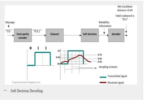
Voltage levels of the received signal at each sampling instant are shown in the figure. The soft decision block calculates the Euclidean distance between the received signal and the all possible codewords.
The minimum Euclidean distance is “0.49” corresponding to “0 1 1” codeword (which is what we transmitted). The decoder selects this codeword as the output. Even though the parity encoder cannot correct errors, the soft decision scheme helped in recovering the data in this case. This fact delineates the improvement that will be seen when this soft decision scheme is used in combination with forward error correcting (FEC) schemes like convolution codes, Goley Code etc.
II. LITERATURE REVIEW
reduce the huge hardware complexity required. The proposed method it improve the transmission system performance level. In this architecture our work is to design a Golay
code based on encoder and decoder architecture using CRC generation technique. This technique is used to reduce the circuit complexity for data transmission and reception process.
Pedro Reviriego et al. [2], Memories that operate in harsh environments, like for example space, suffer a significant number of errors. The error correction codes (ECCs) are routinely used to ensure that those errors do not cause data corruption. However, ECCs introduce overheads both in terms of memory bits and decoding time that limit speed. In particular, this is an issue for applications that require strong error correction capabilities. A number of recent works have proposed advanced ECCs, such as orthogonal Latin squares or difference set codes that can be decoded with relatively low delay. The price paid for the low decoding time is that in most cases, the codes are not optimal in terms of memory overhead and require more parity check bits. On the other hand, codes like the (24,12) Golay code that minimize the number of parity check bits have a more complex decoding. A compromise solution has been recently explored for Bose–Chaudhuri–Hocquenghem codes.
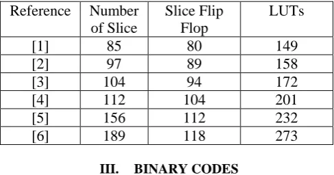
Satyabrata Sarangi et al. [3], this brief lays out cyclic redundancy check-based encoding scheme and presents an efficient implementation of the encoding algorithm in field programmable gate array (FPGA) prototype for both the binary Golay code (G23) and extended binary Golay code (G24). High speed with low-latency architecture has been designed and implemented in Virtex-4 FPGA for Golay encoder without incorporating linear feedback shift register. This brief also presents an optimized and low-complexity decoding architecture for extended binary Golay code (24, 12, 8) based on an incomplete maximum likelihood decoding scheme. The proposed architecture for decoder occupies less area and has lower latency than some of the recent work published in this area. The encoder module runs at 238.575 MHz, while the proposed architecture for decoder has an operating clock frequency of 195.028 MHz. The proposed hardware modules may be a good candidate for forward error correction in communication link, which demands a high-speed system.
P. Adde et al. [4], J.H. Conway and N.J.A. Sloane have introduced an algorithm for the exact maximum-likelihood decoding of the Golay (24, 12) code in the additive white Gaussian noise channel that requires significantly fewer computations than previous algorithms. An efficient bit-serial VLSI implementation of this algorithm is described. The design consists of two chips developed using path programmable logic (PPL) and an associated system of automated design tools for three-μm NMOS technology. It is estimated that this decoder will produce an information bit every 1.6-2.4 μs. Higher speeds can be achieved by using a faster technology or by replicating the chips to perform more operations in parallel.
T.-C. Lin et al. [5], new simple encoding and trellis decoding techniques for Golay codes, based on generalised array codes (GACs) are proposed. The techniques allow the design of (23, 12, 7) Golay and (24, 12, 8) extended Golay codes with minimal trellises. It is shown that these trellises differ only in the last trellis depth with different labelling digits. Xiao-Hong Peng et al. [6], Two product array codes are used to construct the (24, 12, 8) binary Golay code through the direct sum operation. This construction provides a systematic way to find proper (8, 4, 4) linear block component codes for generating the Golay code, and it generates and extends previously existing methods that use a similar construction framework. The code constructed is simple to decode.
Table 1: Comparison of the Encoder architecture considering latency and area
Reference
Number
of Slice
Slice Flip
Flop
LUTs
[1]
85
80
149
[2]
97
89
158
[3]
104
94
172
[4]
112
104
201
[5]
156
112
232
[6]
189
118
273
III. BINARY CODES
Block codes are referred to as (n, k) codes. A block of k information bits are coded to become a block of n bits. n=k + r, where r is the number of parity bits and k is the number of information bits.
The more commonly employed Block codes are: 1. Single Parity-Check Bit Code
2. Repeated Codes 3. Hadamard Code 4. Hamming Code
5. Convolution Code Codes 6. Cyclic Codes
7. Golay Code
8. Extended Golay Codes
Marcel Golay was born in Neuchatel, Switzerland in 1902. He was a successful mathematician and information theorist who was better known for his contribution to real world applications of mathematics than any theoretical work he may have done. Golay‟s sought the perfect code. Perfect codes are considered the best codes and are of much interest to mathematicians. They play an important role in coding theory for theoretical and practical reasons. The following is a definition of a perfect code:
A code C consisting of N codewords of length N containing letters from an alphabet of length q, where the minimum distance d=2e+1 is said to be perfect if:
N
q
q
i
n
ni e
i
)
1
(
)
(
0
(1)
The possible sets of non-zero coordinates as w ranges over W are called code words. In the extended binary Golay code, all code words have the Hamming weights of 0, 8, 12, 16, or 24. Up to relabeling coordinates, W is unique. The perfect binary Golay code, G23 is a perfect code. That is the spheres of radius three around code words form a partition of the vector space.
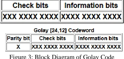
Codeword Structure: A codeword is formed by taking 12 information bits and appending 11 check bits which are derived from a modulo-2 division, as with the CRC. Golay [23, 12] Codeword. The common notation for this structure is Golay [23, 12], indicating that the code has 23 total bits, 12 information bits, and 23- 12=11 check bits. Since each codeword is 23 bits long, there are 223, or 8,388,608 possible binary values. However, since each of the 12-bit information fields has only one corresponding set of 11 check bits, there are only 212, or 4096, valid Golay code words.
Figure 3: Block Diagram of Golay Code
The binary Golay code leads us to the extended Golay code. Codes can be easily extended by adding an overall parity check to the end of each code word.
This extended Golay Code can be generated by the 12 × 24 matrix G = [I12 | A], where I12 is the 12 × 12 identity matrix and A is the 12 × 12 matrix
1
0
0
0
1
1
1
0
1
1
0
1
0
0
0
1
1
1
0
1
1
0
1
1
0
0
1
1
1
0
1
1
0
1
0
1
0
1
1
1
0
1
1
0
1
0
0
1
1
1
1
0
1
1
0
1
0
0
0
1
1
1
0
1
1
0
1
0
0
0
1
1
1
0
1
1
0
1
0
0
0
1
1
1
0
1
1
0
1
0
0
0
1
1
1
1
1
1
0
1
0
0
0
1
1
1
0
1
1
0
1
0
0
0
1
1
1
0
1
1
0
1
0
0
0
1
1
1
0
1
1
1
1
1
1
1
1
1
1
1
0
1
1
0
A
(4)Properties of the extended binary Golay code
o The length of G24 is 24 and its dimension is 12.
o A parity-check matrix for G24 is the 12 × 24 matrix H = [A | I12].
o The code G24 is self-dual, i.e., G⊥ 24 = G24.
o Another parity-check matrix for G24 is the 12 × 24 matrix H0 = [I12 | A] (= G).
o Another generator matrix for G24 is the 12 × 24 matrix G0 = [A | I12] (= H).
o The weight of every codeword in G24 is a multiple of 4.
o The code G24 has no codeword of weight 4, so the minimum distance of G24 is d = 8.
o The code G24 is an exactly three-error-correcting code.
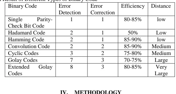
Table 2: Comparison Result of Different Types of Binary Code Binary Code Error
Detection
Error Correction
Efficiency Distance Single
Parity-Check Bit Code
1 1 80-85% low
Hadamard Code 2 1 50% Low
Hamming Code 2 1 85-90% low
Convolution Code 2 2 85-90% Medium
Cyclic Codes 3 2 75-80% Medium
Golay Codes 7 3 70-75% Large
Extended Golay Codes
8 3 80-85% Very
Large
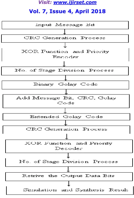
IV. METHODOLOGY
Figure 4: Flow Chart of Golay Encoder and Decoder V. CONCLUSION AND FUTURE SCOPE
In this paper, the Golay code and operation for various encoder and decoder is discussed. This encoding and decoding algorithm have been successfully applied to short block codes such as Golay code. Decoding algorithm consists of syndrome measurement unit, weight measurement unit and weight constraint.
The purpose of this study is to review the published encoding and decoding models in the literature and to critique their reliability effects. We will try to reduce the area, maximum combinational path delay (MCPD) of decoding algorithm of Golay code.
REFERENCES
[1] Pallavi Bhoyar, “Design of Encoder and Decoder for Golay code”, International Conference on Communication and Signal Processing, April 6-8, IEEE 2016, India.
[2] Pedro Reviriego, Shanshan Liu, Liyi Xiao, and Juan Antonio Maestro, “An Efficient Single and Double-Adjacent Error Correcting Parallel Decoder for the (24,12) Extended Golay Code”, IEEE Transactions On Very Large Scale Integration (VLSI) Systems, Vol. 34, No. 3, pp. 01-04, 2016.
[3] Satyabrata Sarangi and Swapna Banerjee, “Efficient Hardware Implementation of Encoder and Decoder for Golay Code”, IEEE Transactions on Very Large Scale Integration (VLSI) Systems 2014.
[4] P. Adde, D. G. Toro, and C. Jego, “Design of an efficient maximum likelihood soft decoder for systematic short block codes,” IEEE Trans. Signal Process. vol. 60, no. 7, pp. 3914–3919, Jul. 2012.
[5] T.-C. Lin, H.-C. Chang, H.-P. Lee, and T.-K. Truong, “On the decoding of the (24, 12, 8) Golay Code,” Inf. Sci., vol. 180, no. 23, pp. 4729– 4736, Dec. 2010.
[7] Ayyoob D. Abbaszadeh and Craig K. Rushforth, Senior Member, IEEE, “VLSI Implementation of a Maximum-Likelihood Decoder for the Golay (24, 12) Code”, IEEE Journal on Selected Areas in Communications. VOL. 6, NO. 3, APRIL 1988.
[8] B. Honary and G. Markarian, “New simple encoder and trellis decoder for Golay codes”, Electronics Letters 9th December 1993 Vol. 29 No. 25.
[9] Xiao-Hong Peng, Member, IEEE, and Paddy G. Farrell, Life Fellow, IEEE, “On Construction of the (24, 12, 8) Golay Codes”, IEEE Manuscript received January 19, 2005; revised July 7, 2005 and December15, 2005, respectively.
[10] W. Cao, “High-speed parallel VLSI-architecture for the (24, 12) Golay decoder with optimized permutation decoding,” in Proc. IEEE Int. Symp. Circuits Syst. (ISCAS), Connecting World, vol. 4. May 1996, pp. 61–64.
[11] W. Cao, “High-speed parallel hard and soft-decision Golay decoder: Algorithm and VLSI-architecture,” in Proc. IEEE Int. Conf. Acoust., Speech, Signal Process. (ICASSP)., vol. 6. May 1996, pp. 3295–3297.
[12] Michael Sprachmann, “Automatic Generation of Parallel CRC Circuits”, 0740-7475/01/$10.00 © 2001 IEEE.
[13] Giuseppe Campobello, Giuseppe Patane`, and Marco Russo, “Parallel CRC Realization”, IEEE Transactions On Computers, Vol. 52, No. 10, October 2003.