Design and Analysis of SRM Drive Control
powered by Fuel Cell
A.Aruna1, Dr A Rajendran2
M.E Scholar, Dept. of EEE, Sona College of Technology, Salem, India1
Asst. Professor, Dept. of EEE, Sona College of Technology, Salem, India2
ABSTRACT: This is change over to eco-friendly energy sources such as solar light, wind power, fuel cell due to
global warming and fossil fuel potential shortage. Non-renewable energy such as fuel cell used for power generation. Power generated by fuel cell used for operating SRM motor. Fuel cell Further next generation there will have advanced power electronics and industrial drives as major components in hybrid motor vehicle designs. This paper includes fuel operated for electric vehicle operation and its applications with using MPPT algorithms with PI and PID controllers.
KEYWORDS: DC motor, MPPT algorithm, PV array, Fuel cell, PID controller.
I. INTRODUCTION
A fuel cell is a device which generates electricity by a chemical process. Fuel cell has two electrodes, one positive and one negative, called, respectively, the anode and cathode. The chemical reactions that generate electricity take place at the electrodes. Hybrid drive using PV array methodology and maximum power point tracking (MPPT) with variation in the irradiance and converter is used to improve accuracy of MPPT. MPPT incremental conductance method is used to derive maximum power range, and with variation in irradiances the MPPT tracks down the power v/s voltage or power v/s current characteristics.
The additional source is fuel cell, it acts as IC engine for electric vehicle, H2 fuel cell is used. When for solar panel if corresponding sunlight is unavailable the fuel cell can be used as secondary source or it can be driven by vehicle along with PV array topology to run with higher efficiencies. For Energy storage system (ESS) a battery is used, it is charged and discharged as per requirements and the charging of batteries becomes complicated as the battery technology improves due to high currents and voltages in the system, so there is necessity of high efficient and chargers having less distortion a useful.
II. RELATEDWORK
The situation in the automotive industry is such that the demands for higher fuel economy and more electric power are driving advanced vehicular power system voltages to higher level. In order to realize the transition smoothly and effectively, energy conservation systems, currently based on power electronics technology. Advanced power electronic converter and traction motor drives will be responsible for a major part of the vehicles energy usage. The automotive market is making rapid development in case of the hybrid electric vehicles. By the time the commercialization of the next generation car comes around, advanced power electronics and moor drives will have already established themselves as prime components of advanced vehicular drive trains. Commercially available HEVs include the Toyota Prius, Toyota highlander hybrid, Toyota Camry hybrid, Lexus RX 400h, Honda Insight, Honda Civic hybrid, Honda Accord hybrid, and Ford Escape hybrid. In the case of future HEVs, power electronic converters and associated motor drives, which control the flow of electrical energy within the HEV power system, promise to be the keys to making HEVs more fuel efficient and emit lower harmful pollutants.
The bidirectional DC-DC converter is able to transfer or balance energy between different dc sources, such as fuel cell and battery hybrid supplied power system. This converter plays an important role in system backup or in reserving energy for the battery. In discharging mode, the converter acts as a two stage boost converter, controlling one power switch to achieve high voltage step up conversion. In charging mode, the converter acts as two cascaded buck converters that control two power switches simultaneously to achieve high voltage step down conversion. Finally, a 24-V/200-V prototype circuit with output power of 200w is implemented to verify the feasibility of the proposed converter. The maximum efficiency levels in discharging and charging modes are about 94.3% and 91.6% respectively. The bidirectional DC-DC converter is widely used in renewable energy applications. This converter is able to transfer or balance energy between two different dc sources, such as fuel-cell and battery hybrid supplied power systems, island photovoltaic generation systems, and wind power system. The bidirectional DC-DC converter can be applied in uninterruptible power supplies to transfer the energy between the source and the battery. The bidirectional DC-DC converter plays an important role in system backup or in reserving energy for the battery. The battery can balance energy between the power source and the load. The voltage difference between the battery and the dc bus is large, thus a bidirectional DC-DC converter with a high step up/down voltage conversion ratio is required.
III.HYBRIDELECTRICVEHICLE
A converter used for propulsion is bidirectional converter with higher power conversions and efficiencies, it operates in two modes buck and boost modes. A permanent magnet synchronous motor is used as electric motor in design of vehicles due to its constant speed and permanent interlocking in the motor, decrease in ripple and harmonics as torque as made choice of PMSM compared with DC series and other motors.
The block diagram of hybrid electric vehicle (HEV) integrated with energy storage system (ESS) which drives traction motor drives is shown in fig1.
The solar and fuel cell operates as resources to the electric vehicle. The electric vehicle operates in three modes: 1. First the resources charges the battery, solar panel uses the maximum power point technique (MPPT) and
fuel cell uses water as fuel for ecofriendly.
2. The battery gets discharged while in acceleration mode by bidirectional operating in boost mode.
3. While braking in vehicle makes the battery to recharge by method of regenerative braking operation buck mode in bidirectional converter.
Fig1 shows the block diagram of hybrid electric vehicle with PI controllers.The coordinated operation of solar sources and fuel cell sources and interconnected converter are investigated for proportional locomotion. The bidirectional converter acts as boost/buck converter depending on the necessity of drive.
A hybrid electric vehicle is a type of hybrid vehicle and electric vehicle that combines a conventional internal combustion engine system with an electric propulsion system. The presence of the electric power train is intended to achieve either better fuel economy than a conventional vehicle or better performance. There is a variety of HEV types, and degree to which each functions as an electric vehicle also varies. The most common form of HEV is the hybrid electric car, although hybrid electric trucks and buses also exist.
IV ANALYSIS OF SIMULATION AND RESULT
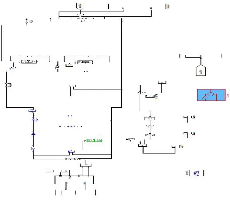
Figure 3 Simulation of normal mode
Fig 4 shows the simulation sub block as per the proposed system. The input voltage and current are measured from the PV panel by using scope. Fig shows that waveform of input current and voltage from PV panel. The input voltage value is taken as 61V and the input current is taken as 1.5A.
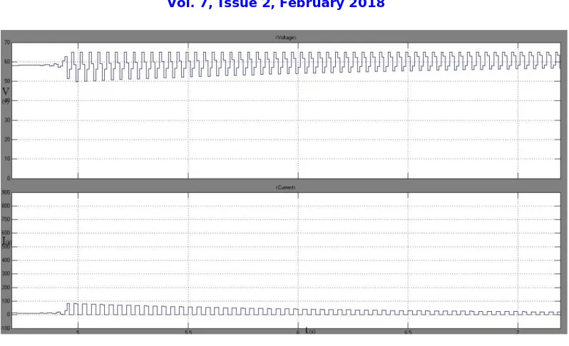
Fig 5: Input voltage and current waveform
Fig 5 shows the fuel cells are used to measure voltage and current waveform and it acts as battery. DC motor is used to measure speed, stator current, torque and EMF waveform by using MOSFET device. Gate pulses are given to device. Gate and decoder value are given to the devices, so the motor are used to measure the waveform of DC motor.
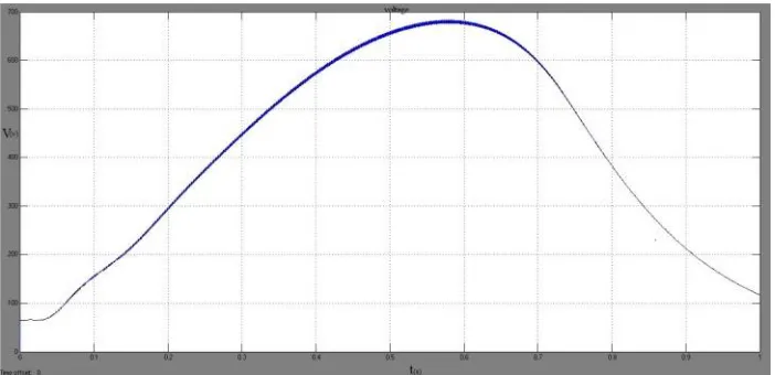
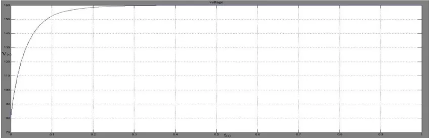
Fig 6 Output voltage from normal mode
Fig 7: Fuel cell voltage and current
The simulation of 6KW fuel cell of hydrogen and air with the propulsion motor, the sepic converter is used to step down the fuel cell ratings as shown in fig 7. The negative current waveform in this figure shows that the fuel cell can drive the vehicle and in braking conditions the battery gets charged. .
Fig 8: Current and EMF waveform of motor
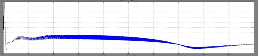
Fig 9: Rotor speed waveform
Fig 9 shows the rotor speed waveform and the value are measured about 4250 RPM. The rating of motor will be 1500RPM and 18W. During acceleration the battery gets discharge and in braking, the battery gets charged again by regenerative braking technique with help of bidirectional converter
Fig 10: Motor torque waveform
Given mechanical input torque as constant 1.4 NM as shown in fig10.Electric propulsion motor used in permanent magnet brushless DC motor which runs along with engine to have locomotion in the vehicle.
The permanent magnet gives best vibrant enactment by having strong torque characteristics, constant speed, permanent interlocking, smooth start off and it also provides smooth acceleration and motor converts mobile energy during regenerative braking and charges the battery.
CONTROL STRATEGIES
Figure 11 shows the control strategies of simulation. Switches are use in the simulation and these switches are operated by means of control strategies. Switches s1 and s4 are operated as forward mode whereas switches s2 and s3 are operated as reverse mode.
REGENERATIVE MODE SIMULATION
Fig 12: Regenerative mode simulation
The design of bidirectional converter with reference speed and giving gate signals to inverter from propulsion motor acts as closed loop simulation of electric drive system. Fig 12 shows the simulation of regenerative mode. In closed loop, for bidirectional controller the two port network method in which PID controller technique is implemented.
Figure 13 Regenerative output voltage waveform
Controller current sources and voltage sources are used as two port network system. The closed loop simulation output waveform, as shown in figure 13.A regenerative brake is an energy recovery mechanism which slows a vehicle or object by converting its kinetic energy into a form which can be either used immediately or stored until needed.
V. CONCLUSION
Hybrid electric vehicle presented here comprises the two ecofriendly sources solar and fuel cell driving a vehicle interconnected by a bidirectional DC/DC converter. Electric power flow among all the sources to vehicle is achieved through bidirectional converter which uses PID controller technique and coordinated operation of solar and fuel cell source and interconnected converter are investigated for proportional locomotion. The simulation results show that the efficient power sharing of hybrid sources with drive by a bidirectional converter. The bidirectional converter acts as buck/boost converter depending on the necessity of drive. The operation of hybrid electric vehicle with new topology fuel cell and solar energy by an interconnection of bidirectional converter using PID control technique for power sharing is investigated by simulation.
In this paper study with fuel cell acts as engine, and in case when there is absence of solar irradiation power, the fuel cell drives the electric vehicle in acceleration mode, and if there is a braking in the drive train, the battery gets charged. The design of bidirectional converter with reference speed and giving gate signal to inverter from propulsion motor acts as closed loop simulation of electric drive system.
REFERENCES
[1]. DeepeshSKanchan and NiranjanHadagali, “Bidirectional DC/DC Converter System for Solar and Fuel Cell Powered Hybrid ElectricVehicle”,
IEEE international conference on magnetics, Machines &Drives(AICERA), 2014 .
[2]. V. K. P. K, C. A. Asha, and M. K. Sreenivasan, “design , simulation and hardware implementation of efficient solar power converter with high mpp tracking accuracy for dc microgrid applications,” pp. 380–387, 2014.
[3]. K. Supreeth, K. S. Sundar, and D. Balamurugan, “Performance Evaluation & Simulation of Solar Power System,” vol. 2, no. 7, 2014. [4]. J. Park, H. Kim, Y. Cho, and C. Shin, “Simple Modeling and Simulation of Photovoltaic Panels Using Matlab / Simulink Modeling of
Photovoltaic Module,” vol. 73, no. Fgcn, pp. 147–155, 2014.
[5]. A. Shukla, M. Khare, and K. N. Shukla, “Modeling and Simulation of Solar PV Module on MATLAB / Simulink,” pp. 18516–18527, 2015. [6]. E. G. S, P. S. Dhivya, and T. Sivaprakasam, “Solar Powered High Efficient Dual Buck Converter for Battery Charging,” pp. 448–452,2013. [7]. J. Patel and G. Sharma, “modeling and simulation of solar photovoltaic module using matlab / simulink,” pp. 225–228, 2013.
[8]. S. S. Mohammed-, “Modeling and Simulation of Photovoltaic module using MATLAB / Simulink,” vol. 2, no. 5, 2011.
[9]. M. Thakur and B. Singh, “Simulink Modal of Triple-Junction Solar Cell and MPPT Based on Incremental Conductance Algorithm for PV System,” vol. 5, no. 9, pp. 92–95, 2015
[10]. Ramya,A, Dhivya,G,DhivyaBharathi,P,Dhyaneswaran, R &Ramakrishnan, P , ‘Comparative Study of Speed Control of 8/6 Switched Reluctance Motor Using PI and Fuzzy Logic Controller’, International Journal of Recent Technology and Engineering, vol.1, no.1, pp.120-125, 2012.
[11]. Shan K B, Joshi L , “Comparative analysis of incremental conductance base MPPT for multi-string photovoltaic system”
engineering(NUiCONE),international conference, nirma university, 2013.
[12]. Karthick and Rajendran,, “Comparison of Different Maximum Power Point Tracking Algorithm for PV Applications”, International Journal of Applied Engineering Research (IJAER), 10 (10), 9758-9763 , 2015.
[13]. Chun-yuan L.,Mian-huan W., Da-weiL.,“Combined control of Single Neuron PID and normal PID of switched reluctance motor,” International Conference on Consumer electronics, Communications and Networks, CECNet 2011, pp 146-149, 16-18 .2011.
[14]. Lukic M., EmadiA.,”State Switching Control Technique for Switched Reluctance Motor Drives: Theory and implementation”, IEEE Transactions on Industrial Electronics,Vol 57,Issue 9, pp 2932-2938,2010.
[15]. Muniraj, C., “Neural Network Based Speed Control for 6/4 Switched Reluctance Motor”, International Conference on Computational Intelligence and Multimedia Applications, vol 1, pp 227-231, 13-15 2007.