ISSN(Online): 2319-8753 ISSN (Print): 2347-6710
I
nternational
J
ournal of
I
nnovative
R
esearch in
S
cience,
E
ngineering and
T
echnology
(A High Impact Factor, Monthly, Peer Reviewed Journal)
Visit: www.ijirset.com
Vol. 6, Issue 10, October 2017
A Study on Airflow over a Plane
Mohd. Rashaduddin1, Ahmed Waheedullah2
Research ScholarDepartment of Mathematics, Dravidian University, Kuppam, (A.P.), India1
Professor Lords Institute of Engineering and Technology, Hyderabad, India2
ABSTRACT: An airfoil is kept in wind tunnel under different pressures and velocities and the results are verified. ANSYS software is used to get lift and drag forces at different velocities. The objective is to simulate an airfoil model to increase its efficiency in terms of lift by managing drag and downforce. On the CFD analysis of the flow over air foil we can conclude that at the zero degree of AOA there is no lift force generated and if we want to increase amount of lift force and value of lift coefficient then we have to increase the value of AOA.
By doing that obviously amount of drag force and value of drag coefficient also increased but the amount of increment in drag force and drag coefficient is quite lower compare to lift force.
KEY WORDS: Airfoil model; ANSYS; Wind tunnel; Aerodynamical parameters.
I.INTRODUCTION
Airplane becomes the need of today’s world. Without it cannot be imagined to have long travelling. Many people ask a simple question "How airplane flies"? The answer is generally not known or just wrong. We hope that the answers provided here will clarify many misconceptions about it.
The important thing to understand is “lift” and lift is easier to understand if one starts with Newton rather than Bernoulli. We will also show that the popular explanation that most of us were taught is misleading and that lift is due to the wing diverting air down. Let us start by defining three descriptions of lift commonly used in textbooks and training manuals.
The first description which is the common and famous is based on the Bernoulli principle. The primary advantage of this description is that it is easy to understand and has been taught for many years. Because of its simplicity, it is used to describe lift in most flight training manuals. The major disadvantage is that it relies on the "principle of equal transit times" which is wrong. This description focuses on the shape of the wing and prevents one from understanding such important phenomena as inverted flight, power, ground effect, and the dependence of lift on the angle of attack of the wing.
The second description can be called as the Physical Description of lift. This description is based primarily on Newton’s laws. The physical description is useful for understanding flight, and is accessible to all who are curious. Little knowledge of Mathematics is enough to yield an estimate of many phenomena associated with flight. This description gives a clear understanding of such phenomena as the power curve, ground effect, and high-speed stalls. However, unlike the mathematical aerodynamics description, the physical description has no design or simulation capabilities. The one which we will discuss by using CFD is used by aeronautical engineers. This description uses complex mathematics and computer simulations to calculate the lift of a wing. These are design tools which are powerful for computing lift.
II.RELATED WORK
From the past work in this field following results can be derived. For an airplane to fly, it must always engage in a tug
of war between the opposing forces of lift versus weight and thrust versus drag. Consider an airplane moving from
right to left and the flow of air moving from left to right.The weight or force due to gravity pulls down on the plane
ISSN(Online): 2319-8753 ISSN (Print): 2347-6710
I
nternational
J
ournal of
I
nnovative
R
esearch in
S
cience,
E
ngineering and
T
echnology
(A High Impact Factor, Monthly, Peer Reviewed Journal)
Visit: www.ijirset.com
Vol. 6, Issue 10, October 2017
blades which is attached to aircraft) and opposes drag caused by air resistance to the airplane. During takeoff, thrust
must be greater than drag and lift must be greater than weight so that the airplane can become airborne.For landing thrust must be less than drag, and lift must be less than weight.
THE FOUR FORCES ACTING ON AN AIRPLANE
III(A).Lift-How Wings Lift the Plane
Airplane wings are shaped to make air move faster over the top of the wing. When air moves faster the pressure of the air decreases. So the pressure on the top of the wing is less than the pressure on the bottom of the wing. The difference in pressure creates a force on the wing that lifts the wing up into the air.
ISSN(Online): 2319-8753 ISSN (Print): 2347-6710
I
nternational
J
ournal of
I
nnovative
R
esearch in
S
cience,
E
ngineering and
T
echnology
(A High Impact Factor, Monthly, Peer Reviewed Journal)
Visit: www.ijirset.com
Vol. 6, Issue 10, October 2017
III (B).Thrust
Thrust is a force created by a power source which gives an airplane forward motion. It can either "pull" or "push" an airplane forward. Thrust is that force which overcomes drag. Conventional airplanes utilize engines as well as propellers to obtain thrust.
III(C) .Drag
Drag is the force which delays or slows the forward movement of an airplane through the air when the airflow direction is opposite to the direction of motion of the airplane. It is the friction of the air as it meets and passes over and about an airplane and its components. The more surface area exposed to rushing air, the greater the drag. An airplane's streamlined shape helps it pass through the air more easily.
It is common experience that a body in motion through a fluid experience a force which in generally a resistance to the motion. However the component of the force normal to the direction to the motion is many times greater than the component resisting the motion.
Airfoil is such an aerodynamic shape that when it moves through air, the air is split and passes above and below the wing. The wing’s upper surface is shaped so the air rushing over the top speeds up and stretches out. This decreases the air pressure above the wing. The air flowing below the wing moves in a straight line so its speed and air pressure remain the same. Since high air pressure always moves toward low air pressure, the air below the wing pushes upward toward the air above the wing. The wing is in the middle, and the whole wing is “lifted.” The faster an airplane moves, the more lift there is. And when the force of lift is greater than the force of gravity, the airplane is able to fly.
IV. NOMENCLATURE OF AN AIRFOIL
ISSN(Online): 2319-8753 ISSN (Print): 2347-6710
I
nternational
J
ournal of
I
nnovative
R
esearch in
S
cience,
E
ngineering and
T
echnology
(A High Impact Factor, Monthly, Peer Reviewed Journal)
Visit: www.ijirset.com
Vol. 6, Issue 10, October 2017
front of the airfoil that has maximum curvature. The trailing edge is defined similarly as the point of maximum curvature at the rear of the airfoil. The chord line is a straight line connecting the leading and trailing edges of the airfoil. The chord length or simply chord is the length of the chord line and is the characteristic dimension of the airfoil section.
V. ANGLE OF ATTACK
If we stretch our arm out through the window of car that is moving at a good speed, we can feel our arm pushed backward. If we hold our arm straight with your hand parallel to the road, and change the angle slightly, you can suddenly feel that it is drown upwards. The hand and arm work like the wing of an airplane and with the right angle (of attack) we can feel a strong lift force.Let AOA is the angle between the oncoming air and a reference line on the airplane or wing. Sometimes the reference line is a line connecting the leading edge and trailing edge at some average point on a wing. Most commercial jet airplanes use the fuselage center line or longitudinal axis as the reference line. It makes no difference what the difference line is as long as it used as consistently. As the nose of the wing turns up, angle AOA increases, and lift increases. Drag goes up also, but not as quickly as lift. During take-off an airplane builds up to a certain speed and then the pilot “rotates” the plane that is, the pilot manipulates the controls so that the nose of the plane comes up and the wings generate enough lift to take the plane into the air. Since an airplane wing is fixed to the fuselage, the whole plane has to rotate to increase the wing's angle of attack. Front wings on racecars are fabricated so the angle of attack is easily adjustable to vary the amount of down force needed to balance the car for the driver.
VI. LIFT AS A FUNCTION OF ANGLE OF ATTACK
There are many types of wing: conventional, symmetric, conventional in inverted flight, the early biplane wings that looked like warped boards, and even the proverbial "barn door." In all cases, the wing is forcing the air down, or more accurately pulling air down from above. What all of these wings have in common is an angle of attack with respect to the oncoming air. It is this angle of attack that is the primary parameter in determining lift. The lift of the inverted wing can be explained by its angle of attack, despite the apparent contradiction with the popular explanation involving the Bernoulli principle. A pilot adjusts the angle of attack to adjust the lift for the speed and load. The popular explanation of lift which focuses on the shape of the wing gives the pilot only the speed to adjust.
ISSN(Online): 2319-8753 ISSN (Print): 2347-6710
I
nternational
J
ournal of
I
nnovative
R
esearch in
S
cience,
E
ngineering and
T
echnology
(A High Impact Factor, Monthly, Peer Reviewed Journal)
Visit: www.ijirset.com
Vol. 6, Issue 10, October 2017
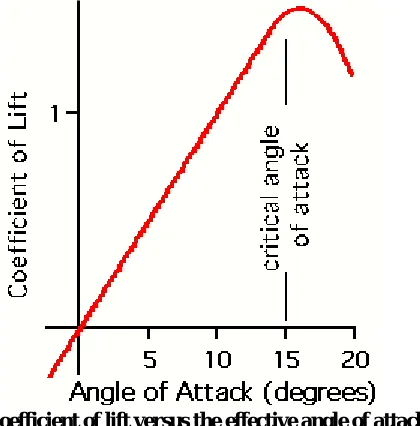
747 or a barn door. The role of the angle of attack is more important than the details of the airfoil's shape in understanding lift.
Fig Coefficient of lift versus the effective angle of attack.
Typically, the lift begins to decrease at an angle of attack of about 15 degrees. The forces necessary to bend the air to such a steep angle are greater than the viscosity of the air will support, and the air begins to separate from the wing. This separation of the airflow from the top of the wing is a stall.
VII. COEFFICIENT OF DRAG AND COEFFICIENT OF LIFT
The drag equation is given as
= Where coefficient of drag is =
This statement says that the drag force on any object is proportional to the density of the fluid and proportional to the square of the relative speed between the object and the fluid.
In fluid dynamics is a dimensionless quantity that is used to quantify the drag or resistance of an object in a fluid
environment such as air or water. It is used in the drag equation where a lower drag coefficient indicates the object will have less aerodynamic or drag. The drag coefficients always associated with a particular surface area.
The drag coefficient of any object comprises the effects of the two basic contributors to fluid dynamics drag: skin friction and from drag. The drag coefficient of a lifting airfoil or hydrofoil also includes the effects of lift induced drag. The drag coefficient of a complete structure such as an aircraft also includes the effects of interference drag. The overall drag coefficient defined in the usual manner is the reference area depends on what type of drag coefficient is being measured. For automobiles and many other objects, the reference area is the
projected frontal area of the vehicle. This may not necessarily be the cross sectional area of the vehicle, depending on where the cross section is taken and for an airfoil the surface area is a plane form area. The lift equation,
=1 2
ISSN(Online): 2319-8753 ISSN (Print): 2347-6710
I
nternational
J
ournal of
I
nnovative
R
esearch in
S
cience,
E
ngineering and
T
echnology
(A High Impact Factor, Monthly, Peer Reviewed Journal)
Visit: www.ijirset.com
Vol. 6, Issue 10, October 2017
A fluid flowing past the surface of a body exerts a force on it. Lift is the component of this force that is perpendicular to the oncoming flow direction. It contrasts with the drag force, which is the component of the surface force parallel to the flow direction. If the fluid is air, the force is called an aerodynamic force.
VIII. RELATIONSHIP BETWEEN ANGLE OF ATTACK, COEFFICIENT OF DRAG AND COEFFICIENT OF LIFT
The lift coefficient (CL) is a dimensionless coefficient that relates the lift generated by a lifting body to the fluid
density around the body, the fluid velocity and an associated reference area. A lifting body is a complete foil-bearing
body such as a fixed-wing aircraft. CL is a function of the angle of the body to the flow, its Reynolds number and
it’s Mach number. The lift coefficient CL refers to the dynamic lift characteristics of a two-dimensional foil section,
with the reference area replaced by the foil chord.
The lift coefficient of a fixed-wing aircraft changes with angle of attack. If the angle of attack increases then lift coefficient also increases up to the maximum lift coefficient, after which lift coefficient decreases.
As the angle of attack of fixed-wing aircraft increases, separation of the airflow from the upper surface of the wing becomes more pronounced, leading to a reduction in the rate of increase of the lift coefficient.
A symmetrical wing has zero lift at 0 degrees angle of attack. The lift curve is also influenced by wing platform. A swept wing has a lower, flatter curve with a
higher critical angle. Identically the value of drag coefficient is zero at the zero
angle AOA and it increases slowly till the stall condition and at the time of stall as well as after stall it increase readily. Particular airspeed, the airspeed at which the aircraft stalls varies with the weight of the aircraft, the load factor, the center of gravity of the aircraft and other factors. However the aircraft always stalls at the same critical angle of attack. The critical or stalling angle of attack is typically around 15° for many airfoils.
IX.CFD ANALYSIS PROCESS
Fluid (gas and liquid) flows are governed by partial differential equations which represent conservation laws for the mass, momentum, and energy. Computational Fluid Dynamics (CFD) is the art of replacing such PDE systems by a set of algebraic equations which can be solved using digital computers.
Computational fluid dynamics (CFD) is a branch of fluid mechanics that uses numerical analysis and data structures to
solve and analyze problems that involve fluid flows. Computers are used to perform the calculations required to simulate the interaction of liquids and gases with surfaces defined by boundary conditions. With high-speed supercomputers, better solutions can be achieved. Ongoing research yields software that improves the accuracy and speed of complex simulation scenarios such as transonic or turbulent flows. Initial experimental validation of such software is performed using a wind tunnel with the final validation coming in full-scale testing, e.g. flight tests.
The fundamental basis of almost all CFD problems is the Navier–Stokes equations, which define many single-phase (gas or liquid, but not both) fluid flows. These equations can be simplified by removing terms
describing viscous actions to yield the Euler equations. Further simplification, by removing terms
describing vorticity yields the full potential equations. Finally, for small perturbations in subsonic and supersonic flows (not transonic or hypersonic) these equations can be linearized to yield the linearized potential equations.
Computational Fluid Dynamics (CFD) provides a qualitative (and sometimes even quantitative) prediction of fluid flows by means of
• Mathematical modeling (partial differential equations) • Numerical methods (discretization and solution techniques) • Software tools (solvers, pre- and post processing utilities)
CFD enables scientists and engineers to perform ‘numerical experiments’
ISSN(Online): 2319-8753 ISSN (Print): 2347-6710
I
nternational
J
ournal of
I
nnovative
R
esearch in
S
cience,
E
ngineering and
T
echnology
(A High Impact Factor, Monthly, Peer Reviewed Journal)
Visit: www.ijirset.com
Vol. 6, Issue 10, October 2017
S.No Step Process
1 Problem statement Information about the flow
2 Mathematical
model
Generate 3D model
3 Mesh generation Cells
4 Space
discretization
Coupled ODE/DAE systems
5 Time
discretization
Algebraic system Ax=b
6 Iterative solver Discrete function values
7 CFD software Implementation
8 Simulation run Parameters, stopping criteria
9 Post processing Visualization analysis of data
X. MESH GENERATION
In order to analyze fluid flow, flow domains are split into smaller sub domains. The governing equations are then discretized and solved inside each of these sub domains. The meshed area around the aerofoil is shown in below figure
XI. INPUTS AND BOUNDARY CONDITION
ISSN(Online): 2319-8753 ISSN (Print): 2347-6710
I
nternational
J
ournal of
I
nnovative
R
esearch in
S
cience,
E
ngineering and
T
echnology
(A High Impact Factor, Monthly, Peer Reviewed Journal)
Visit: www.ijirset.com
Vol. 6, Issue 10, October 2017
Operating parameters
S.No Input Value
1 Flow velocity 0.15 Mach or 51m/s
2 Temperature(operating) 300k
3 Pressure 101325pa
4 Fluid density 1.225kg/m3
5 Kinematic viscosity 1.4607 x e-5
6 Reynolds number 3.5 x e-6
7 Length 1m
8 AOA 0 and 6 degrees
9 Fluid Air
XII. CONTOURS OF STATIC PRESSURE OVER AIRFOIL
The static pressure of the air is simply the weight per unit area of the air above the level under consideration. For instance, the weight of the column of air with a cross-sectional area of 1sft and extending upward from sea level through the atmosphere is 2116 lb. The sea level static level is therefore 2116 psf. Static pressure is decrease as altitude is increased because there is less air weight above. At 18,000 ft altitude the static pressure is about half that at sea level .The Amalgamation (combination) of static pressure and dynamic pressure is known as total pressure.
XIII. CONTOURS OF VELOCITY MAGNITUDE OVER AIRFOIL
At the 0 degree of AOA the velocity contours are same as symmetrical and at 6 degree of AOA the stagnation point is slightly shift towards the trailing edge via bottom surface hence it will create low velocity region at lower side of the airfoil and higher velocity.
Conclusion
Based on the CFD analysis of the flow over air foil we can conclude that at the zero degree of AOA there is no lift force generated and if we want to increase amount of lift force and value of lift coefficient then we have to increase the value of AOA. By doing that obviously amount of drag force and value of drag coefficient also increased but the amount of increment in drag force and drag coefficient is quite lower compare to lift force. The amount of air diverted by the wing is proportional to the speed of the wing and the air density. The vertical velocity of the diverted air is proportional to the speed of the wing and the angle of attack.
Variables AOA =00 AOA = 60
Lift force 0.2486N 888.7298N
Drag force 21.79 N 40.0502N
Drag coefficient 0.01373 0.02566
Lift coefficient 0.00015 0.56947
REFERENCES
[1].Anderson Jr, Computational Fluid Dynamics – The basics with Applications, McGraw-Hill Series in Mechanical Engineering Series, McGraw Hill, Inc, 1995.
[2].Lift-Formula-Subject: Aeronatics, TOPIC: Lift DESCRIPTION: A set of problems dealing with the aerodynamic lift
equation. CONTRIBUTEDBY: CarolHodanbosi EDITED BY: Jonathan G. Fairman - August 1996 [3]. CFD Analysis of an Aerofoil by Karna S. Patel, Saumil B. Patel, Utsav B. Patel, Prof. Ankit P. Ahuja
UVPCE, Ganpat University (www.uvpce.ac.in) , International Journal of Engineering Research ISSN:2319-6890)(online),2347-5013(print) Volume
ISSN(Online): 2319-8753 ISSN (Print): 2347-6710
I
nternational
J
ournal of
I
nnovative
R
esearch in
S
cience,
E
ngineering and
T
echnology
(A High Impact Factor, Monthly, Peer Reviewed Journal)
Visit: www.ijirset.com
Vol. 6, Issue 10, October 2017
[4]. How Airplanes Fly: A Physical Description of Lift by David Anderson Fermi National Accelerator Laboratory Batavia IL [email protected] Scott Eberhardt Dept. of Aeronautics and Astronautics University of Washington Seattle WA 91895-2400 [email protected] . The Aviation
History Online Museum.Created November 28, 2001.Updated June 6, 2015.
[5]. International Journal of Mechanical Engineering and Technology Volume 7, Issue 2, March-April 2016, pp. 91–104, Article ID: