Lee, Michael E. DCAP: A Multichannel Protocol for Single Interface 802.11 Wireless Mesh
Networks. (Under the direction of Assistant Professor Mihail L. Sichitiu).
Wireless ad hoc networks are gaining popularity as quick and inexpensive methods
of connecting computers. In particular, Wireless Mesh Networks (WMNs) are becoming a
viable method of offering Internet access to entire neighborhoods. One reason WMNs are
attractive is because of their use of inexpensive 802.11 wireless hardware. However, using
802.11 standard compliant hardware has a major limitation: the 802.11 standard does not
support the use of multiple channels in the same network. Because of this limitation, wireless
802.11 networks are not able to achieve the traffic throughput possible when utilizing all
the available channels.
To increase the throughput in WMNs, this paper proposes a novel protocol
al-lowing the use of multiple channels with a single wireless 802.11 interface. This protocol,
Distributed Channel-switching Accessory Protocol, or DCAP, requires no modifications to
the 802.11 MAC layer. DCAP defines the methods wireless nodes use to send and receive
traffic across multiple channels with a single wireless interface. The key concept of our
approach is Home Channels. A node’s Home Channel is the only wireless channel on which
the node receives data. By requiring the sender to change to the receiver’s Home Channel
to transmit a packet, all nodes know on which channel to transmit each packet. Once on
the receiver’s Home Channel, the transmission of the packet follows the 802.11 standard.
In this work, DCAP is implemented in the ns-2 event simulator to evaluate its
performance. DCAP is implemented as a separate protocol immediately above the 802.11
MAC layer in ns-2. The implementation of DCAP makes no modifications to the 802.11
MAC protocol. A series of performance evaluation tests are performed to compare DCAP’s
performance against a single channel 802.11 network. These tests compare the throughput of
the two networks in a variety of different network traffic conditions and network topologies.
The simulation results show the network with the DCAP protocol achieves significantly
higher throughputs than the single channel 802.11 network (up to four times in a network
Mesh Networks
by
Michael E. Lee
A thesis submitted to the Graduate Faculty of North Carolina State University
in partial fulfillment of the requirements for the Degree of
Master of Science
Computer Networking - Electrical and Computer Engineering
Raleigh
2006
Approved By:
Dr. Wenye Wang Dr. Alexander G. Dean
Dr. Mihail L. Sichitiu
Biography
Michael Lee was born and grew up in Arkansas. He completed his early education
in Russellville, AR, and graduated from Russellville High in 1999. He graduated from
the University of Arkansas at Fayetteville, AR in May 2003 with a bachelor’s degree in
Computer Engineering and a minor in Mathematics. He then began full time work toward
the Master of Science degree in Computer Networking at North Carolina State University
Acknowledgements
I would like to thank my advisor, Dr. Mihail Sichitiu, for his patient guidance and
support. This thesis would not have been possible without his constructive criticism and
suggestions. I am grateful to my advisory committee members, Dr. Wenye Wang and Dr.
Alexander G. Dean, for their suggestions and comments on my work. I also appreciate my
collegues in the WALAN Research Group, especially Jangeun Jun, for all their suggestions.
I would like to thank my parents, David and Becky Lee, for their support
through-out my educational journey. Most of all, I want to thank my wife, Angela, for her patience
Contents
List of Tables vii
List of Figures viii
List of Abbreviations ix
1 Introduction 1
1.1 Related Work . . . 3
1.1.1 Multi-Radio, Custom MAC . . . 3
1.1.2 Multi-Radio, 802.11 MAC . . . 5
1.1.3 Single-Radio, Custom MAC . . . 6
1.1.4 Single-Radio, 802.11 MAC . . . 7
1.2 Contribution . . . 9
2 DCAP Design 10 2.1 Overview . . . 10
2.2 Receiving Packets . . . 12
2.3 Sending Packets . . . 12
2.4 Listen Time (TL) . . . 15
2.5 Determining a Receiver’s Channel . . . 18
2.6 Channel Table . . . 19
2.7 Neighbor Discovery (TN) . . . 20
2.8 Gateway Node . . . 21
2.9 Home Channel Assignment . . . 21
2.9.1 Hyacinth Channel Assignment Algorithm . . . 23
2.9.2 Differences Between Channel Assignment Algorithms . . . 24
2.9.3 DCAP’s Modified Channel Assignment Algorithm . . . 25
3 Implementation 27 3.1 Test One: Two Nodes . . . 29
3.2 Test Two: Three Nodes . . . 31
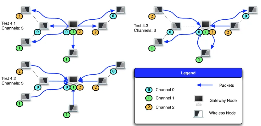
3.4 Test Four: Three Channels . . . 37
4 Performance Evaluation 40 4.1 Dependency on Channel Request Packet Timeout (TQ) . . . 42
4.2 Dependency on Listen Time (TL) . . . 45
4.3 Dependency on Home Channel Assignment Interval (TC) . . . 45
4.4 Dependency on Neighbor Discovery Interval (TN) . . . 47
4.5 Dependency on Channel Table Purge Interval (TP) . . . 49
4.6 Dependency on Channel Load (Poisson Interarrival Time) . . . 51
4.7 Dependency on Number of Channels . . . 55
4.8 Dependency on Number of Nodes . . . 57
4.9 Dependency on Distance Between Nodes . . . 61
4.10 Dependency on Node Positions . . . 63
5 Conclusion and Future Work 64
Bibliography 67
List of Tables
List of Figures
1.1 Wireless Mesh Network . . . 2
2.1 DCAP is Implemented Between the IP and the MAC Layers . . . 11
2.2 Node A Sending a Packet to Node B . . . 13
2.3 Sending a Broadcast Packet on Multiple Channels . . . 14
2.4 Sending on Busy Channel . . . 15
2.5 A Value ofTL to Small Leading to Transmission Failures From Node A to B When B Also Sends to C . . . 17
2.6 Hop Distance Between Neighbors . . . 22
3.1 Ns-2 Implementation of the Gateway Node . . . 28
3.2 Test One: Two Nodes . . . 30
3.3 Subtest 1.3 Throughput . . . 30
3.4 Test Two: Three Nodes . . . 31
3.5 Subtest 2.3 Throughput . . . 32
3.6 Test Three: Multihop Network . . . 33
3.7 Subtest 3.1 Throughput . . . 34
3.8 Subtest 3.2 Throughput . . . 35
3.9 Subtest 3.3 Throughput . . . 36
3.10 Subtest 3.4 Throughput . . . 38
3.11 Test Four: Three Channels . . . 38
3.12 Subtest 4.3 Throughput . . . 39
4.1 Performance Evaluation Network . . . 41
4.2 Dependency of Throughput and Delay as a Function of Channel Request Packet TimeoutTQ . . . 43
4.3 Dependency of Throughput and Delay as a Function of Listen TimeTL . . 44
4.4 Dependency of Throughput and Delay as a Function of Home Channel Se-lection IntervalTC . . . 46
4.6 Dependency of Throughput and Delay as a Function of Channel Table Purge
Interval TP . . . 50
4.7 Dependency of Throughput and Delay as a Function of Offered Load . . . . 52
4.8 Dependency of Throughput and Delay as a Function of HTTP traffic on Offered Load . . . 54
4.9 Dependency of Throughput and Delay as a Function of Number of Channels 56 4.10 Dependency of Throughput and Delay as a Function of the Number of Nodes in the Network . . . 58
4.11 Dependency of Throughput and Delay as a Function of the Distance Between Nodes . . . 60
4.12 Dependency of Throughput and Delay as a Function of Node Positions . . . 62
A.1 Subtest 1.1 Throughput . . . 71
A.2 Subtest 1.2 Throughput . . . 72
A.3 Subtest 1.3 Throughput . . . 72
A.4 Subtest 2.1 Throughput . . . 73
A.5 Subtest 2.2 Throughput . . . 73
A.6 Subtest 2.3 Throughput . . . 74
A.7 Subtest 3.1 Throughput . . . 74
A.8 Subtest 3.2 Throughput . . . 75
A.9 Subtest 3.3 Throughput . . . 75
A.10 Subtest 3.4 Throughput . . . 76
A.11 Subtest 3.5 Throughput . . . 76
A.12 Subtest 3.6 Throughput . . . 77
A.13 Subtest 4.1 Throughput . . . 77
A.14 Subtest 4.2 Throughput . . . 78
List of Abbreviations
• 802.11 - IEEE 802.11 Wireless Standard
• ACK - Acknowledgment
• AODV - Ad Hoc On-Demand Distance Vector Routing
• AP - Access Point
• CBR - Constant Bitrate
• CTS - Clear to Send
• DCAP - Distributed Channel-switching Accessory Protocol
• DIFS - Distributed Inter Frame Space
• FHSS - Frequency-Hopping Spread Spectrum
• GPS - Global Positioning System
• HTTP - Hyper Text Transfer Protocol
• IP - Internet Protocol
• MAC - Media Access Control
• NAV - Network Allocation Vector
• PDR - Packet Delivery Ratio
• RTS - Request to Send
• TCP - Transport Control Protocol
• TDMA - Time Division Multiple Access
Chapter 1
Introduction
Wireless networks based on the IEEE 802.11 standard [14] have become a
com-monplace in aspects of our daily lives over the past five years. This popularity is due to
the inexpensive 802.11 hardware and the easy deployment of wireless networks. Although
these networks are common, they typically operate in infrastructure mode. In this mode, a
wireless node connects directly to an Access Point (AP). All wireless traffic is received by
the AP and forwarded to the correct destination. Using the APs, a wireless node is able to
send and receive packets from other networks such as the Internet. This type of network
is called a single-hop with infrastructure network since all wireless nodes must be within
transmission range of the AP.
Wireless networks are also capable of operating in ad hoc mode. In ad hoc
net-works, the wireless nodes are not required to be in radio range of an AP. Instead, traffic
from wireless nodes is forwarded by the other wireless nodes to reach the destination. Ad
hoc networks are beneficial because they can create a network in places where it is difficult
or nearly impossible to create a wired network. Ad hoc networks are gaining popularity
for use in connecting neighborhoods to the Internet without the expense of laying the wires
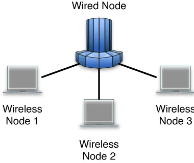
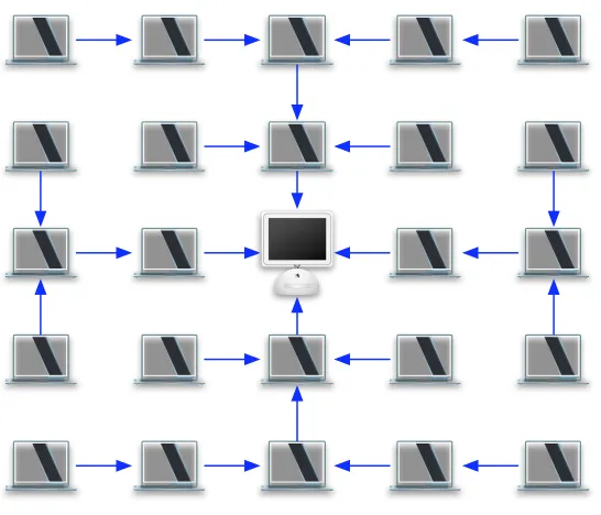
necessary for wired networks [7]. This type of network, known as a Wireless Mesh
Net-work (WMN), is an ad hoc netNet-work that is connected to a wired netNet-work (see Figure 1.1).
WMNs can be used to connect wireless nodes with the Internet through special wireless
nodes called gateways. The gateways in a WMN connect the wireless ad hoc network to
Inte rne t
G atew ay N o de
W ire le ss N ode W ire le ss
No de W ire less
N od e
W ire less N od e W ire le ss
No de
W ire le ss No de W ir
e less N ode W ire less
N ode
Le ge n d
W ired L ink W ire le ss Lin k
Figure 1.1: Wireless Mesh Network
Although WMNs allow for the creation of a network without any physical wires,
their throughput is less than that of a single-hop with infrastructure network. This decrease
in throughput is the result of more wireless nodes competing for the wireless channel. Nodes
outside the transmission range of a gateway node must have their traffic forwarded by nodes
closer to the gateway. This results in more transmissions per packet in an WMN than in a
single-hop with infrastructure network. In an ad hoc network, as the distance between the
sender and receiver increases, the throughput decreases due to interference from wireless
neighbors [7]. This is caused by a wireless node having to compete with its neighbors for
exclusive access of the channel before sending.
To further compound the throughput problem in a WMN, the network’s traffic
will concentrate around the gateway nodes. All traffic must go through a gateway node,
since most traffic in a WMN is going from the wireless nodes to the wired network (or vice
versa). This increase in traffic flowing through the gateway nodes causes an increase in
competition for the channel around the gateway nodes, and decreases the throughput in
the network.
Throughput in a WMN can be increased by increasing the bandwidth available
non-overlapping channels for wireless nodes to use, and the 802.11a standard provides 12
non-overlapping channels. According to the 802.11 standard, each of these channels has
a fixed amount of bandwidth. By following the 802.11 standard, a network is able to
utilize the inexpensive 802.11 hardware instead of expensive, custom hardware. Although
multiple channels exist in the 802.11 standards, most ad hoc networks operate only on
a single channel. A method of increasing the throughput in a multi-channel network by
utilizing 802.11 hardware will result in higher throughput while still following the 802.11
standard. By utilizing multiple channels, the interference between neighbors will also be
reduced [3]. The following section describes several different methods currently available
for increasing the throughput in WMNs by utilizing multiple channels.
1.1
Related Work
There are two methods of utilizing multiple channels in wireless mesh networks:
multi-radio and single-radio. Multi-radio solutions utilize multiple radios on each wireless
node to achieve greater throughput in wireless networks with multiple channels.
Single-radio solutions, however, attempt to increase the throughput in a wireless network with
using only a single wireless radio. Although multi-radio solutions are more expensive to
implement, they typically achieve a higher throughput than single-radio solutions.
Multi-channel wireless solutions can be further divided into methods that use an
unmodified 802.11 MAC protocol and methods that use custom MAC protocols. The
advan-tage of using the unmodified 802.11 MAC protocol is that existing 802.11 wireless hardware
can be used to implement the solution. Since 802.11 wireless hardware has become
inex-pensive due to mass production, using unmodified 802.11 wireless hardware would decrease
the cost of deployment compared to custom MAC solutions. The following sections describe
existing solutions in each of these categories.
1.1.1 Multi-Radio, Custom MAC
Most methods of utilizing multiple channels in a WMN involve using multiple
wireless interfaces with a custom MAC protocol. In these methods, each interface is located
channel. Although this method would allow the use of all channels in the network, it does
not scale well for networks with large numbers of channels. A network with 20 channels
would require 20 wireless interfaces in each node. Another method is to use only one
wireless interface to send packets while using multiple wireless radios to receive packets
[9]. In this protocol each node has a wireless radio listening on each interface for incoming
packets. When a node sends a packet, it will randomly choose an idle interface to send
the packet, giving priority to the previously used interface. Since all nodes are listening on
every channel, the receiver will be able to receive a packet sent on any channel. Although
this solution can utilize all channels in the network, it requires a seperate wireless radio
listening on each channel in the network.
Most methods use N wireless interfaces in a network with M available channels
where N ≤ M. This allows a more scalable solution while still gaining the benefits by
using multiple interfaces. In these networks with fewer wireless interfaces than available
channels, a method of assigning channels to interfaces is needed to utilize the multiple
chan-nels while maintaining the network’s connectivity. Several static and dynamic algorithms
have been developed that assign a pair of interfaces within transmission range to a channel
[8]. The static algorithms are centralized and do not allow the channels to be reassigned
to other nodes to accommodate changes in traffic patterns. Although the dynamic
algo-rithms allow channel reassignment to accommodate traffic pattern changes, they require
time synchronization and contain overhead for coordinating the channel reassignment.
Several other custom protocols use multiple interfaces to increase the throughput
in a WMN by designating one channel as a control channel [19], [6], [20]. These protocols
use the control channel to reserve a data channel for the exclusive use of transmitting a
single packet. In a network withM available channels, this allowsM−1 simultaneous data
transmissions. These protocols exchange messages similar to Request to Send (RTS) and
Clear to Send (CTS) messages on the control channel to reserve a pre-selected idle data
channel for exclusive use during the transmission of the packet. This method guarantees
that there is no channel contention on any channel except the control channel.
All nodes keep one wireless interface on the control channel and use the remaining
wireless interfaces to send data packets on the other channels. When a node sends a
RTS-type message on the control channel, the message will specify the data channel the packet
will be sent on and how long the transmission will take. All nodes that receive the RTS-type
it is busy for the duration of the transmission. This protocol requires information, including
the NAV, to be stored for each channel.
The primary disadvantage of these protocols is the bottleneck the control channel
creates. In order to send any packet, a node must send the RTS-type message on the control
channel. When many nodes are trying to transmit at once, there will be heavy competition
for access to the control channel. This competition can lead to under-utilization of the
data channels as a result of collisions on the control channel. In cases when there are a
few large packets to be transmitted, the control channel’s bandwidth will be wasted due to
infrequent RTS-type and CTS-type messages, while the data channels’ bandwidth will be
entirely consumed by the large data payloads.
1.1.2 Multi-Radio, 802.11 MAC
Another method of utilizing multiple channels in a WMN is to use multiple 802.11
wireless interfaces. This is less expensive and easier to deploy than using custom interfaces;
however, the 802.11 MAC protocol only works on a single channel. The Hyacinth network
accommodates this limitation by assigning each 802.11 wireless interface to operate on a
specific channel [12], [10], [11]. Two variations of the Hyacinth network exist. One performs
the channel assignment using a centralized method, and the other performs the channel
assignment using a distributed method.
The Hyacinth network can perform static channel allocation by sending link load
estimations to a centralized location [12]. The centralized location will perform two tasks:
interface-to-channel binding and neighbor-to-interface binding. These tasks are different
because a node has fewer interfaces than neighbors, so the centralized location must ensure
the network maintains connectivity when performing the neighbor-to-interface binding. The
centralized location also has to maximize throughput in the network by carefully performing
the interface-to-channel binding to minimize the amount of interference.
A centralized approach to channel allocation does not scale well for large networks,
so the Hyacinth network was modified to allow dynamic channel allocation [10], [11].
Dy-namic channel assignment is performed by the nodes sending link load estimates to the
node’s neighbors. Before a node assigns any of its interfaces to a channel, it must first
create a tree out of the network topology. The tree will contain the gateway node as the
node’s UP-NIC corresponds to a DOWN-NIC of the node’s parent. Nodes can only assign
channels to their DOWN-NICs. A node’s UP-NICs must always stay on the same channel
as the parent’s corresponding DOWN-NIC, so the node’s parent determines the channel of
UP-NICs. This method of assigning channels allows the Hyacinth network to efficiently use
multiple channels.
The Hyacinth network achieves a higher throughput by using multiple 802.11
inter-faces. This requirement of multiple interfaces is the primary disadvantage of the Hyacinth
network. Multiple interfaces are more expensive and consume more power than a single
in-terface. Using a single wireless interface to harness multiple channels for increased
through-put results in a lower cost of deployment. The following two sections describe methods of
using a single wireless interface to send and receive packets on multiple channels.
1.1.3 Single-Radio, Custom MAC
Several protocols use a single wireless interface with a custom MAC to utilize
multiple channels for increased throughput. These protocols work by dividing time into
slots, called Time Division Multiple Access (TDMA). TDMA requires clock synchronization
between nodes. The Multi-channel MAC (MMAC) protocol breaks time up into beacon
intervals [13]. At the beginning of each beacon interval nodes negotiate which channel they
will use for the remainder of the beacon interval. The Group Allocation Multihop Multiple
Access (GAMMA) protocol also uses TDMA to reserve channels, but it reserves channels
for only a single slot instead of for the entire interval.
The Hop Reservation Multiple Access (HRMA) protocol uses TDMA to reserve
time slots for each transmitting node; however, it also uses slow frequency-hopping spread
spectrum (FHSS) when sending packets [15]. In slow FHSS, a node will change channels
according to a set schedule. HRMA uses FHSS to decrease the effects of noise on the
channels by limiting the time nodes spend on each channel.
Another use of slow FHSS is performed by Channel-Hopping Multiple Access
(CHMA) and Receiver-Initiated Channel-Hopping with Dual Polling (RICH-DP) [16], [17].
In both of these protocols, a common channel sequence is used by all nodes. When two
nodes need to send to one another, they will exchange RTS and CTS frames. A successful
RTS/CTS exchange will reserve that channel for use by the two nodes. While the two nodes
the hop sequence by switching to the next channel in the sequence. This allows other nodes
to reserve other channels and transmit while the original two nodes are still transmitting.
Although all of these single-radio, custom MAC solutions achieve greater
through-put than a single channel 802.11 network, they all require clock synchronization. Clock
synchronization results in more network traffic or specialized hardware to maintain the
synchronization. By frequently communicating each node’s current time, nodes can
syn-chronize their clocks. However, this synchronization requires additional network traffic for
the time exchange. The additional traffic decreases the number of other packets that can
be sent in the network. Extra communication can be avoided by using specialized
hard-ware. By using more accurate hardware clocks on each wireless node, synchronization can
be maintained longer. Using Global Positioning System (GPS) hardware, also allows nodes
to synchronize their clocks. However, these specialized hardware solutions result in more
expensive wireless nodes. The additional traffic or specialized hardware prevent protocols
requiring clock synchronization from scaling well to large networks. Also, most of these
protocols have synchronization or contention time slots that introduce overhead regardless
of how many nodes need to transmit.
1.1.4 Single-Radio, 802.11 MAC
Using a single wireless interface results in less energy consumption, and using a
802.11 interface results in easier deployment due to more commonly found and inexpensive
hardware. However, utilizing multiple channels using a single, unmodified 802.11 wireless
interface is difficult because the 802.11 standard does not support utilizing multiple channels
in the same network. The Slotted Seeded Channel Hopping (SSCH) protocol is able to use
unmodified 802.11 hardware by implementing the SSCH protocol immediately above the
802.11 hardware [18]. Although SSCH does not modify the 802.11 hardware, it does change
the behavior of the 802.11 standard by reimplementing some of the 802.11 MAC protocol’s
functionality like retransmission of RTS frames.
SSCH uses channel hopping (identical to FHSS) to utilize the multiple interfaces.
SSCH uses a different channel hopping schedule for each node. Nodes are made aware of
each other’s channel hopping schedules by periodically propagating their channel hopping
schedules to their neighbors. A node propagates its channel hopping schedule by
that channel will receive the updated information. SSCH maintains packets in per-neighbor
FIFO queues. When a node changes to a channel, it determines which receivers it believes
are currently on the channel by examining its copies of their channel hopping schedules. It
sends any queued outgoing packets for all neighbors it believes to be on the current channel
until it changes to the next channel in its schedule.
Because SSCH stores all outgoing packets in per-neighbor FIFO queues and only
transmits to neighbors on the current channel, SSCH introduces an additional delay when
sending packets. Before being sent, outgoing packets must wait until the node changes to a
channel where it believes the receiver is present. Because a receiving node might not be on
the current channel (even through its channel hopping schedule indicates it should be there),
SSCH must keep a copy of all packets until it realizes they have been successfully received.
SSCH does not drop any packets until all packets to that destination have been dropped for
the duration of an entire cycle through its channel hopping schedule. It must wait through
the entire cycle before dropping any packets to make sure the receiver’s channel hopping
schedule does not overlap with its own.
Because nodes are frequently on different channels, broadcast packets transmitted
on any one slot are likely to reach only a small subset of the nodes that are within
trans-mission range. SSCH addresses this issue by periodically retransmitting broadcast packets
so they statistically are received by a significant number of the nodes in transmission range.
SSCH relies on upper layer protocols to ensure the destination receives the proper broadcast
packets since it does not guarantee a broadcast packet reaches all its neighbors.
Since SSCH uses channel hopping, clock synchronization is needed. Although
SSCH will work when all nodes’ clocks in the network are not properly synchronized, its
throughput will be dramatically less. Simulations of SSCH showed a significant decrease in
throughput when clocks drifted more than 100 microseconds apart. Also, SSCH only works
well when all nodes know each other’s channel hopping schedules and current offsets. If
a sender does not have this information accurate, it will not be able to determine which
channel the receiver currently occupies to send packets to it. Since channel hopping schedule
updates are performed in periodic broadcast packets, neighbors are not guaranteed to receive
these updates.
To avoid modifications to the 802.11 hardware, SSCH must circumvent some of the
802.11 hardware functionality. To maintain control over transmission attempts, the 802.11
a single RTS frame for each packet. SSCH requires these modifications because it handles
packet retransmissions in a significantly different manner. Although SSCH uses a single
802.11 interface, it requires clock and schedule synchronization between nodes, introduces
delays while sending packets, and does not guarantee the reception of broadcast packets to
all nodes in transmission range.
1.2
Contribution
The contribution of this work is the design and performance evaluation of a
sin-gle interface, 802.11, multi-channel protocol named DCAP (pronounced ’d-cap’). DCAP
(Distributed Channel-switching Accessory Protocol) is a new protocol to augment,
with-out modification, the 802.11 MAC protocol withwith-out requiring clock synchronization. Using
DCAP, a WMN is able to achieve more network throughput than is possible with
cur-rent 802.11 networks using only a single channel. This work demonstrates this increased
throughput with a series of validation tests and performance evaluations.
The remainder of this paper is organized into the following sections:
• Chapter 2 - Describes the DCAP protocol and how it sends and receives on multiple
channels.
• Chapter 3 - Provides modifications to the ns-2 simulator that implements DCAP.
• Chapter 4 - Evaluates the performance of the proposed protocol.
• Chapter 5 - Concludes the paper and describes future research that could result from
Chapter 2
DCAP Design
2.1
Overview
DCAP (Distributed Channel-switching Accessory Protocol) is a protocol to utilize
multiple channels of a 802.11 wireless network to maximize the network’s capacity. DCAP
defines the methods wireless nodes use to switch channels, receive packets, and send packets.
It allows a wireless node with a single 802.11 wireless interface to utilize multiple channels
to achieve better throughput than networks using only a single channel. DCAP distributes
the network’s traffic load across all available channels in the network. By distributing this
load, DCAP can achieve better throughput than a network utilizing only a single channel.
DCAP allows multiple, simultaneous communications to occur between wireless
nodes inside transmission range of one another. Since each node can receive packets on a
different channel, multiple nodes within transmission range of each other can be sending
packets on different channels at the same time. Although only a single transmission can
occur within transmission range on each channel, using multiple channels allows multiple
transmissions to occur simultaneously. This ability to use multiple transmissions to occur
allows DCAP to achieve a higher throughput than is possible in a network using only a
single channel.
DCAP achieves this better throughput without making any modifications to the
layer (see Figure 2.1). It intercepts packets going to the 802.11 MAC protocol [14] and, based
on the destination MAC address, determines which channel is the receiver’s Home Channel.
It then switches to this channel before passing the packet to the 802.11 MAC. Because of
this separation from the MAC protocol, DCAP will work with any 802.11 network. DCAP
will also work with any routing protocols since it works under the IP protocol.
P h y s ic a l L a y e r 8 0 2 .1 1 P h y s ic a l
D a ta L in k L a y e r 8 0 2 .2
8 0 2 .1 1 M A C
N e tw o rk L a y e r IP
D C A P
Figure 2.1: DCAP is Implemented Between the IP and the MAC Layers
DCAP achieves a much higher throughput by each node determining a “Home
Channel” that they will receive packets on. A node will only receive packets on its Home
Channel, and will always reside on this channel when idle. In order to send a packet,
the sender must change to the Home Channel of the receiving node so both nodes will be
on the same channel. By using this method to send and receive, the network maintains
connectivity while taking advantage of multiple channels.
The following sections describe in detail how DCAP works in conjunction with the
802.11 MAC protocol to send and receive packets on multiple channels. These sections also
explain the information obtained and used by DCAP, and how nodes determine their Home
2.2
Receiving Packets
A node will stay on its Home Channel unless it is currently sending a packet.
While on its Home Channel, a node will listen to the channel so it can receive incoming
packets. When the node sends a packet, it will switch to the receiver’s Home Channel to
send the packet, but it will return immediately to its Home Channel to listen for incoming
packets. When a node returns to its Home Channel, it will remain there for TL time to
receiving incoming packets sent on its Home Channel (see Section 2.3). Whenever a node
detects a channel is busy, it will set its backoff timer according to the 802.11 standard. It
will then return to its Home Channel until the timer expires so it can receive any incoming
packets sent during this time.
For example, when a sender, node A, wants to send a packet to node B, it will
change to node B’s Home Channel (see Figure 2.2). If node A is sending a unicast packet,
it will send an RTS frame to node B. Node B will respond by transmitting a CTS to node
A. Node A will then send the data, and node B will send an ACK. This entire exchange of
information is done on the receiver’s (B’s) Home Channel. Once node A has received the
ACK, it will then switch back to its Home Channel and remain there for TL time. Node B
will continue to listen on its Home Channel for other incoming packets.
By always staying on its Home Channel when not sending, a node is available
to receive incoming packets for the maximum amount of time. Nodes are always able to
determine which channel to send to a neighbor because nodes only receive packets on their
Home Channels. The only information a node must have to send a packet is the receiver’s
Home Channel. The Home Channel assignment algorithm, discussed in Section 2.9, is the
method nodes use to select their Home Channel.
2.3
Sending Packets
To send a packet, DCAP must change to the Home Channel of the receiver.
How-ever, it must first identify the receiver. When a node sends a packet, DCAP will intercept
the packet from the IP protocol. After intercepting the packet, DCAP examines the packet’s
MAC address. If the MAC address indicates the packet is a broadcast packet, then DCAP
must broadcast the packet on every channel (see Figure 2.3). DCAP transmits broadcast
C h a n n e l 1 A 's H o m e C h a n n e l
A
B
C h a n n e l 2 B 's H o m e C h a n n e l
D IF S R T S
C T S S IF S
A C K S IF S D A T A S IF S A c h a n g e s
t
o c h a n n e l2
T L
A
B
A c h a n g e s
t
o c h a n n e l 1
Figure 2.2: Node A Sending a Packet to Node B
times so it can send the packet on each channel which is the major source of overhead in
DCAP. To send a broadcast packet, DCAP starts broadcasting the packets on its Home
Channel then continues broadcasting the packet on each channel sequentially in increasing
order. When a node changes to the channel, it will wait for Distributed Inter Frame Space
(DIFS) + backoff time before sending the broadcast packet. After the packet has been
successfully sent, DCAP will change to the next channel, wait for DIFS + backoff time, and
repeat the transmission. Once DCAP has broadcast the packet on every channel, it returns
to its Home Channel to listen for incoming packets.
If, after intercepting a packet from the IP protocol, DCAP determines from the
packet’s MAC address that the packet is a unicast packet, it will only transmit the packet
on the receiver’s Home Channel. The Channel Table (described in detail in Section 2.6)
contains the MAC address and Home Channel of each node in transmission range. If the
node does not find the receiver’s Home Channel in its Channel Table, then it will need to
send a Channel Request Packet to determine the receiver’s Home Channel (see Section 2.5).
However, if DCAP’s Channel Table contains the Home Channel of the receiver, DCAP will
C h a n n e l 2
A 's H o m e C h a n n e l D A T A D IF S C h a n n e l 1
D A T A D IF S
C h a n n e l 4
D A T A D IF S C h a n n e l 3
D A T A D IF S A c h a n g e s to c h a n n e l3
A c h a n g e s to c h a n n e l4
A c h a n g e s to c h a n n e l 1
A c h a n g e s to c h a n n e l 2
T L
Figure 2.3: Sending a Broadcast Packet on Multiple Channels
Channel, DCAP transmits the packet identical to the 802.11 standard.
After the node changes to the receiver’s Home Channel, it will determine if the
channel is idle. If it is, then the node will wait DIFS time before sending the RTS packet
(see Figure 2.2). The node will continue to follow the 802.11 standard while receiving the
CTS, sending the data, and receiving the ACK. After the node has finished receiving the
ACK, it will return to its Home Channel to listen for incoming packets. The node will listen
on its Home Channel for TL seconds so it can receive incoming packets before leaving its
Home Channel again (see Figure 2.2). Determining theTL time is explained in more detail
in Section 2.6. If a node changes to the receiver’s Home Channel and detects that the node
is busy, it will set its backoff timer according to the 802.11 standard. It will then return
to its own Home Channel to listen for incoming packets while waiting. When the backoff
timer expires, it will change to the receiver’s Home Channel again to send (see Figure 2.4).
If the channel is detected as busy again, it will set its backoff timer and return to its Home
Channel again. Only when it detects the receiver’s Home Channel as idle, will it wait the
DIFS time and send the packet.
C h a n n el 1 A 's H om e C h an n el
A
B
C h a n n e l2 B 's H o m e C h a nn e l
D IFS R T S
C T S S IFS
A C K S IFS D A T A S IFS
A
B
A ch a ng e s
t
o ch a nn e l2
A c ha n ge s to ch an n el 1
A ch a ng e s
t
o cha n ne l2
A ch an g es to ch a nn e l1
A ch a ng e s
t
o ch a nn e l2
A c ha n ge s to cha n n el 1
T L
BUS Y
BA C KO FF BA C KO F F
Figure 2.4: Sending on Busy Channel
the node to receive incoming packets during the duration of the backoff timer. If a node
is backing off on its Home Channel and it receives an incoming packet, it will pause its
backoff timer and receive the packet according to the 802.11 standard. After the reception
is complete, it will resume its backoff timer and continue to listen on its Home Channel.
After the backoff timer expires, it will then switch to the receiver’s Home Channel to
transmit the packet.
2.4
Listen Time (
T
L)
Since a node must change to the receiver’s Home Channel to send a packet, it might
leave its Home Channel for the duration of the transmission. Ideally, its Home Channel
will be different than the receiver’s to insure minimal interference (see Section 2.9). If its
Home Channel is different than the receiver’s Home Channel, it will have to leave its Home
Channel to send the packet. If a node has many packets to send, it will frequently leave
its Home Channel. During the time a node is sending packets, it will not be on its Home
Channel to receive incoming packets.
If a node were to immediately leave its Home Channel when it has a packet to send,
insure a node stays on its Home Channel long enough to receive incoming packets, DCAP
will delay sending a new packet, with a receiver on another channel, to the 802.11 MAC
protocol forTLseconds. ThisTLtime must be long enough for the receiving node to receive
an RTS frame from a sender before it changes from its Home Channel. Once theTLtime has
expired, DCAP will send down the next packet to the 802.11 MAC protocol. By delaying
the packet from being received by the 802.11 MAC protocol and returning to the node’s
Home Channel, DCAP forces the 802.11 MAC to receive incoming packets. The 802.11
MAC protocol will receive incoming packets since it will be unaware that it has any packets
to send. If the next packet to be sent has a destination node on the sender’s Home Channel,
then DCAP does not wait theTL time before sending the packet.
TheTLvalue also reduces the number of packets dropped because a node is unable
to reach the receiver. If the sender sends a packet on the receiver’s Home Channel while the
receiver is on another channel, then the sender’s transmission will fail. However, the sender
may detect an idle channel because no other nodes are transmitting on the receiver’s Home
Channel (see Figure 2.5). This problem is called the Absent Receiver Problem because the
receiver is not on its Home Channel to receive the packet. In this case, the RTS transmission
will time out, and the sender will set its backoff timer and return to its Home Channel.
After the backoff time expires, the sender will return to the receiver’s Home Channel to
transmit the RTS frame again.
In this scenario, the sender is unable to set it’s NAV to wait until the receiver’s
transmission is complete, since it does not hear the receiver’s transmission. The sender
must continue to send the RTS frames on the receiver’s Home Channel until the receiver
responds with a CTS frame. This process follows the 802.11 standard for retransmitting
RTS frames. As defined in the 802.11 standard, the retransmission of RTS frames will
end after seven retransmissions. At this point, the packet will be dropped and the next
packet sent. By using a sufficiently large value forTL, DCAP can ensure that a node stays
on its Home Channel long enough to receive the RTS frame so the number of RTS frame
C h a n n e l 2 B 's H o m e C h a n n e l
D IFS R T S
B c h a n g e s to ch a n n e l3
T L
A
B
B ch a n g e s to c h a n n e l3
C
C h a n n e l 3 C 's H o m e C h a n n e l
D IFS R T S
C T S S IFS
A C K S IFS D A T A S IFS
A
B
C
C h a n n e l 1 A 's H o m e C h a n n e l
A
B
C
A ch a n g e s
to c h a n n e l2
BA C KO FF
D IFS R T S
BA C KO FF
D IFS R T S
C T S S IFS
A c h a n g e s
to ch a n n e l1
A ch a n g e s
to ch a n n e l2
A c h a n g e s
to ch a n n e l 1
A ch a n g e s
to c h a n n e l2
Figure 2.5: A Value of TL to Small Leading to Transmission Failures From Node A to B
2.5
Determining a Receiver’s Channel
When DCAP intercepts a unicast packet, it must look up the receiver’s MAC
address in its Channel Table. If the Channel Table contains the receiver’s Home Channel,
then it will switch to that channel to send the packet (see Section 2.3). However, if the
Channel Table does not contain the receiver’s Home Channel, the sender must request
it from its neighbors. The sender requests a node’s Home Channel by broadcasting a
Channel Request Packet. The Channel Request Packet contains the MAC address of the
host whose Home Channel is needed. The Channel Request Packet is broadcasted in the
same manner as other broadcast packets (see Section 2.3). The node will transmit the
Channel Request Packet on all channels starting with its Home Channel and continuing
sequentially in increasing order (see Figure 2.3).
When a node receives a Channel Request Packet, it will examine the requested
MAC address. If the receiving node does not know the Home Channel of the requested MAC
address, it will ignore the Channel Request Packet. However, if the node knows the Home
Channel of the requested MAC address (even if its MAC address is not the requested one),
it will send a Channel Reply Packet back to the sender. The Channel Reply Packet contains
the MAC address of the requested node and the node’s Home Channel. Any node hearing
the Channel Reply Packet will update their Channel Table with the requested node’s MAC
address and Home Channel. After the original sender receives the Channel Reply Packet
and records the requested node’s MAC address and Home Channel, it will transmit the
original packet to the receiver.
Since the Channel Request Packet is a broadcast packet, the receiving nodes will
not acknowledge the successful reception of the packet. Packet collisions or radio interference
can cause the broadcast packet to become corrupted and discarded by the receivers. To
ensure that the neighbors successfully receive the Channel Request Packets, the sender will
set a retransmission timer, TQ. Once the TQ timer has expired, the sender will retransmit
the Channel Request Packet on all channels. When the sender receives a Channel Reply
Packet or a Home Channel Packet that resolves its channel request, it will cancel the timer
and proceed to send the original packet. However, if the request has not been resolved after
three failed Channel Request Packet transmissions, the node will cancel the TQ timer and
drop the original packet.
store the original packet in DCAP’s packet queue. This packet queue contains all the
packets whose receiver’s Home Channels are not known. Whenever a node receives a Home
Channel Packet (see Section 2.6) or Channel Reply Packet, it will check it’s DCAP queue
for any packets it is able to send. When it determines it can send a packet from the queue,
it will send the packet down to the 802.11 MAC protocol when the MAC protocol indicates
it is available to send another packet. This process ensures that packets in the DCAP queue
are sent before other packets.
2.6
Channel Table
Each node maintains a table of MAC addresses and Home Channels. This table,
called the Channel Table, is used to resolve nodes’ MAC addresses with their Home Channels
when sending packets. The Channel Table contains information about each of the node’s
one-hop and two-hop neighbors. Each entry in the Channel Table contains the following
information:
• MAC address
• Home Channel
• time of the last successful transmission
• reported channel load
• hop distance
The MAC address is used as the index into the table and identifies the information
as belonging to that neighbor. The Home Channel is the channel on which the neighbor
receives packets on (see Section 2.2). The time of the last successful transmission is used to
purge old entries from the Channel Table. The reported channel load and the hop distance
are used in the distributed channel assignment algorithm (see Section 2.9).
The hop distance to a node is the number of hops it takes a packet to reach the
node. This includes the receiver and all nodes that forward the packet towards the receiver.
Every wireless node keeps entries in its Channel Table of all nodes within a two-hop distance.
a hop distance of one-hop are used to determine Home Channels when sending packets since
a node can only directly communicate with nodes with a one-hop distance.
Since information in a node’s Channel Table can become inaccurate over time, a
node must purge old entries occasionally. A node determines which entries are accurate by
using the time of the last successful transmission. After every successful transmission to
a host, the sender updates the Channel Table entry corresponding to that host with the
current time. A node also updates its Channel Table when it receives a Home Channel
Packet (see Section 2.7). To purge old entries, every TP seconds the time of the Channel
Table’s entries are examined and all entries that have a time older than TP seconds are
removed. This ensures that the Channel Table contains accurate information.
2.7
Neighbor Discovery (
T
N)
Determining a receiver’s Home Channel after DCAP intercepts a packet to send
introduces a small delay. To reduce this delay, DCAP provides a method of proactive Home
Channel discovery through the exchange of Home Channel Packets. These packets are
exchanged every TN seconds. Home Channel Packets are also used in the Home Channel
assignment algorithm (see Section 2.9). To proactively discover neighbors, a node will
periodically send Home Channel Packets. Home Channel Packets include a node’s MAC
address and its Home Channel. The Home Channel Packet also includes the MAC addresses
and Home Channels of all of the node’s neighbors within transmission range (one-hop
neighbors).
When a node receives a Home Channel Packet, it will update its Channel Table
with the sender’s MAC address and Home Channel (see Section 2.6). It will also update the
Channel Table with all of the MAC addresses and Home Channels of the sender’s one-hop
neighbors. When the node updates its Channel Table with the sender’s information, it will
update the record’s time of last successful transmission. A node does not update this time
when updating records of the sender’s one-hop neighbors. A node only updates the time
value of the sender because, by sending the Home Channel Packet, the sender verifies the
information is still accurate. Information about the sender’s one-hop neighbors might not
be accurate, so the one-hop neighbor’s time of last successful transmission should not be
A node will broadcast a Home Channel Packet every TN seconds. The periodic
broadcasts of Home Channel Packets allows nodes to maintain accurate information about
their neighbors and reduces the delay caused by sending Channel Request Packets to
re-solve a node’s Home Channel. DCAP does not require this neighbor discovery ability to
function, since it will obtain the a receiver’s Home Channel as needed by sending
Chan-nel Requests Packets. Using a small value of TN will introduce more overhead as nodes
frequently broadcast Home Channel Packets unnecessarily. Using a larger value ofTN will
reduce this overhead but introduce the overhead and delay associated with Channel Request
Packets. The neighbor discovery ability can be disabled completely with aTN value of zero.
Performance results of the TN value are discussed in Section 4.4.
2.8
Gateway Node
The gateway node is a special wireless node in the wireless mesh network. Since
most traffic in a wireless mesh network is coming from or going to the Internet or wired
network, all this traffic will flow through the gateway node. To handle the higher traffic
demands, the gateway node is constructed differently than the other wireless nodes. The
gateway node will have a separate wireless 802.11 interface for each channel used in the
network. This allows the gateway to simultaneously carry on several communications at
once by utilizing the different channels. However, only the single gateway node uses multiple
wireless interfaces. Since the gateway node has a separate wireless interface for each channel,
its wireless interfaces do not change channels to send packets. Instead, the gateway node
sends the packets to the correct wireless 802.11 interface based on the Home Channel of the
packet’s MAC address.
2.9
Home Channel Assignment
Nodes receive all incoming packets on their Home Channel and send packets to
their neighbors on their neighbor’s Home Channel. To minimize interference between
neigh-boring nodes, a node must select a Home Channel different from all nodes in interference
range. The interference range is assumed to be twice the reception range. Thus, all
In addition, a node will be able to detect the presence of communication from nodes up
to two-hops away. Although a node cannot receive the communication from nodes farther
than one-hop away, the node will be able to detect that the channel is currently busy if the
node is two-hops away. Since nodes over two-hops away do not cause interference, a node
can select the same Home Channel as a node that is three-hops away. However, since nodes
two-hops and closer cause interference, a node must select a different Home Channel from
all nodes up to two-hops away.
1 áh o p 2 áh o p
3 áh o p
Figure 2.6: Hop Distance Between Neighbors
The channel assignment algorithm that DCAP uses is based on the algorithm used
in the Hyacinth architecture [1]. Hyacinth utilizes multiple channels in a wireless mesh
network by using multiple 802.11 interfaces per node. They use the channel assignment
algorithm to determine the channels that each of a node’s interfaces should remain on.
Although they use multiple network interfaces, their algorithm can be modified for DCAP’s
channel assignment requirements. DCAP uses a modified version of their algorithm to select
which channel a node should designate as its Home Channel. The remainder of this section
will be divided into three parts. First, the Hyacinth channel assignment algorithm will be
described. Next, the differences between the Hyacinth channel assignment algorithm and
the modified algorithm used by DCAP will be covered. Last, DCAP’s modified channel
2.9.1 Hyacinth Channel Assignment Algorithm
In the Hyacinth network, multiple channels are used by equipping all wireless
nodes with multiple interfaces. Unlike DCAP, the wireless nodes do not change channels
to send packets. Instead, a wireless node can only send packets to those neighbors that
have a wireless interface located on the same channel as the node’s interface. A wireless
node with two interfaces can only use two channels. Network connectivity issues arise
since a network might have more available channels than its nodes have interfaces. For the
Hyacinth network, proper channel assignment for each interface is important to maintain
network connectivity. Channel assignment is also done to increase network throughput, so
a node attempts to select the channel with the most available bandwidth.
The Hyacinth network has a single gateway node and multiple wireless nodes.
Before the channel assignment algorithm is run, the nodes arrange themselves in a tree
with the gateway node as the root. Multiple gateway nodes can be used, but each will
result in a separate tree. Building the tree allows several of Hyacinth’s algorithms to be run
such that they understand the path and the number of hops to the gateway.
The Hyacinth channel assignment algorithm divides the channel assignment
prob-lem into two subprobprob-lems: neighbor-interface binding and interface-channel binding. In
neighbor-interface binding, a node divides its wireless interfaces into UP-NICs and
DOWN-NICs. UP-NICs are used to communicate with a node’s parents, while DOWN-NICs are
used to communicate with a node’s children. Most nodes attempt to split the available
interfaces equally between DOWN-NICs and UP-NICs. However, nodes further from the
gateway will assign fewer interfaces as UP-NICs to help aggregate traffic.
The primary reason behind the distinction between UP-NICs and DOWN-NICs is
to prevent channel changes from propagating throughout the network. A node selecting a
new channel for one of its interfaces might cause all of the node’s neighbors to select new
channels for their interfaces. Also, to maintain network connectivity, a node must verify
that both it and its neighbors have interfaces on the same channel. To solve these problems,
a node can only assign a new channel to one of its DOWN-NICs. Its UP-NICs will always
stay on the channel that the node’s parent determines.
For the second subproblem, interface-channel binding, the channel for each
inter-face will be determined. The channel assignment of a node’s UP-NICs is done by the node’s
within interference range. Interference can be caused by any of a node’sk-hop neighbors,
where k is the ratio of interference range to transmission range. Thus, each node must
periodically exchange individual usage information with all of its (k+ 1)-hop neighbors to
create a valid estimate of the channel’s usage.
A node must communicate with all (k+1)-hop neighbors because it will be making
a channel assignment decision for itself as well as all of its children. Since all nodes khops
away from its children can cause interference, it must use the channel usage information of its
children’sk-hop neighbors (its (k+1)-hop neighbors). A node’s channel usage is determined
by the amount of data a node transmits. The channel usage estimate is computed by the
weighted combination of the sum of all interference neighbor’s channel usage and the number
of nodes on the channel.
Once a node has computed the channel usage of all channels, it will then select
a new channel for its DOWN-NICs. A node will select a new channel for only one of its
DOWN-NICs everyTC time units. Channel assignment priority is given to nodes closer to
the gateway since they need more bandwidth to forward traffic. During the assignment,
the node will exclude all channels containing interference neighbors with higher priority.
This restriction allows nodes closer to the gateway to choose the channels with the least
usage. Once a node has determined its new channel, it will send a message including its
new channel to its children so they can reassign their corresponding UP-NICs. The node
will then send its new channel usage information to each of its (k+ 1)-hop neighbors to
ensure they know the load of the new channel.
2.9.2 Differences Between Channel Assignment Algorithms
Since the Hyacinth channel assignment algorithm is used in a network with multiple
wireless interfaces on each node, it had to be modified to be used in DCAP. Only minimal
modifications were required to apply the Hyacinth algorithm to a wireless nodes with a
single interface. The primary modification is the elimination of the UP-NICs. Since DCAP
dynamically changes channels to send packets, it does not have the connectivity problems
present in the Hyacinth network. Also, since DCAP uses only a single interface per wireless
node, the number of DOWN-NICs is always one. These two changes eliminates the
neighbor-interface binding subproblem solved by the Hyacinth network.
sub-problem. Like Hyacinth, DCAP makes channel assignments based on channel usage.
How-ever, unlike Hyacinth, DCAP uses the amount of data a node receives for the channel usage
computation instead of the amount of data transmitted. Since, in DCAP, a node transmits
on many channels, but always receives only on one, basing the channel usage on the amount
of data receives is more appropriate. DCAP bases the channel usage only on unicast packets
since broadcast packets are sent on all channels.
Since DCAP does not have access to a network topology tree to determine
par-ents, children, and distance to the gateway, DCAP handles channels of interference
neigh-bors slightly differently. Instead of excluding interference neighneigh-bors closer to the gateway,
DCAP places priority on channels with no interference neighbors. In addition to selecting
channels with no interference neighbor closer to the gateway, this method also selects
chan-nels with no other nodes that might cause interference. Since selecting a channel with no
interference neighbor present might be impossible, DCAP does not require their selection.
Instead, DCAP will prioritize it by selecting a channel that has more channel usage with no
interference neighbors over a channel with less channel usage with interference neighbors.
The last modification to the Hyacinth channel assignment algorithm DCAP makes
is to reduce the number of neighbors it must exchange information with. Since DCAP is
only making the channel assignment decision for itself, it only needs to base the channel
assignment decision on the channel usage of its k-hop neighbors instead of its (k+ 1)-hop
neighbors.
2.9.3 DCAP’s Modified Channel Assignment Algorithm
DCAP’s channel assignment algorithm uses the modifications to the Hyacinth
algorithm described in Section 2.9.2. DCAP’s channel assignment algorithm is run every
TC+X seconds whereXis a random number between 0 and 0.1. The random value is used
to ensure that two nodes are not likely to change Home Channels at the same time. If two
nodes were to change Home Channels at the same time, they might both independently
decide to change their Home Channel to the same new channel. This would result in more
contention on that channel and could decrease the throughput in the network. EveryTC+X
seconds, each node decides which channel has the least load and designates this channel
as its new Home Channel. Priority is given to channels that do not contain interference
The channel assignment algorithm determines the load of each channel by summing
the channel utilization reported by all nodes on that channel. Each node calculates the
channel utilization by determining the total size of all unicast packets received in each
TC+X time interval. Only unicast packets are used, because broadcast packets are sent
on all channels and received by all nodes. The load calculation is shown in Equation 2.1.
The load on channeliis the sum of the channel utilization of all nodesj that have a Home
Channel ofi. The channel utilization ofj is the total size in bytes (B) of all unicast packets
received by node j since node j last changed its Home Channel (TC +X). The result of
Equation 2.1 is the traffic load on each channel in the network. This value is used to select
the least loaded channel to designate as a node’s Home Channel.
channel loadi =
X B TC +X
j
,∀ nodesj with Home Channel i (2.1)
Once a node has determined the load of each channel, it will choose the channel
with the least load. Priority will be given to channels with no one-hop or two-hop neighbors
to reduce the amount of interference. A node will select the channel with the least load
that contains no one-hop or two-hop neighbors. If all channels contain at least one one-hop
or two-hop neighbor, then the node will chose the channel with the least load that contains
only two-hop neighbors. If no channels exist that contain only two-hop neighbors, then the
node will select the least loaded channel out of all available channels. This priority system
is used to reduce the amount of interference caused by nodes one-hop or two-hops away
Chapter 3
Implementation
The performance of DCAP was studied through a series of validation tests and
performance evaluations. The validation tests were done to verify that DCAP performed
as expected and to examine any overheads that DCAP introduced. The performance
eval-uation (discussed in Chapter 4) examines DCAP’s performance in real-world scenarios.
The performance of DCAP was studied using ns-2 simulations. Ns-2 is a discrete
event simulator supporting simulation of wireless networks, including the 802.11 MAC
pro-tocol [2]. Ns-2 was modified to allow wireless nodes to change channels during the
sim-ulation. DCAP was implemented in ns-2 by inserting the new protocol between the IP
protocol and 802.11 MAC Protocol. Ns-2 does not support wireless nodes with multiple
network interfaces, so the gateway node was implemented as a wired node connected to a
separate wireless node for each interface on the gateway (see Figure 3.1). The gateway’s
interface nodes were connected to the wired node with network links with zero latency and
a transmission rate of 100 gigabits per second. The result emulates a single gateway node
with multiple interfaces since the network links introduce insignificant delay.
Ns-2’s AODV (Ad hoc On-Demand Distance Vector Routing) routing protocol only
supports a pure wireless ad hoc network, and does not support routing between wireless
and wired nodes. Other routing methods are required to allow wireless nodes to determine
proper routes to the wired nodes. To overcome this limitation, Ali Hamidian’s AODV+
module was used as the routing protocol [5]. Ali Hamidian modified ns-2’s AODV protocol
W ire d N o d e
W ire le s s N o d e 3 W ire le s s
N o d e 2 W ire le s s
N o d e 1
Figure 3.1: Ns-2 Implementation of the Gateway Node
nodes in both the DCAP and non-DCAP networks can resolve routes to and from the wired
node portion of the gateway node.
To prove the correctness of the modifications and determine DCAP’s performance,
a series of validation tests were performed. These tests computed the network throughput of
various network topologies to compare the performance of DCAP against a single-channel
network (non-DCAP). These tests used the same network topology and traffic patterns
between the DCAP and non-DCAP networks to make this comparison. All DCAP variables
were set to specific values and the nodes were prevented from selecting new Home Channels.
Nodes were precisely placed before the beginning of the simulation and there was no node
movement during the simulation. Chapter 4 discusses the impact of the DCAP variables
on the network throughput.
The number of channels utilized in the network, the number of nodes in the
net-work, and the number of nodes sending and receiving from the gateway are different for
each test; however, the distance between the nodes and the DCAP variables are all the
same. All nodes are located 200 meters apart so they are within transmission range. Three
nodes located in a straight line, however, are not all within transmission range since the
400 meter distance between the first and third is beyond the reach of the node’s radio. The
DCAP values TC, TN, and TP were all set to values beyond the end of the test to disable
TL was set to the time it would take to send and receive the RTS and CTS frames (0.67
milliseconds).
Each node’s Home Channel is manually set to achieve an optimal distribution of
channels, and nodes were prevented from selecting a new Home Channel. At the beginning
of each test, nodes sent Home Channel Packets to determine their neighbors and sent a
single data packet to allow AODV to setup the routes. After 50 seconds, selected nodes
start to send or receive data from the gateway. These data traffic flows were constant bitrate
(CBR) traffic, and lasted for 110 seconds. The start and duration of the data traffic was
constant for all tests, but the traffic rate was varied for each test. The results of each test
are shown in the following sections as graphs of the network throughput as a function of
the CBR traffic rate. The following sections describe the different test scenarios and discuss
their results. Selected graphs of each test’s throughput are shown below, but all the graphs
of the validation results are shown in Appendix A.
3.1
Test One: Two Nodes
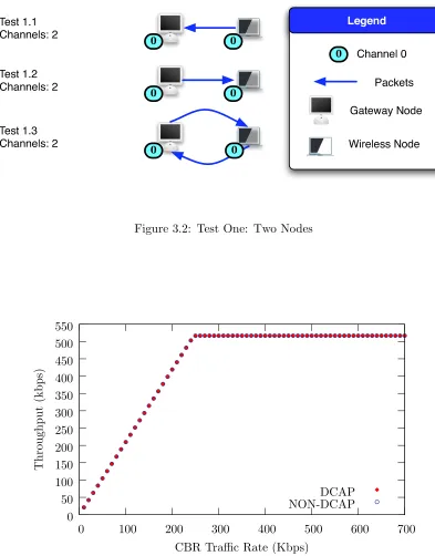
A network of two nodes was designed with one gateway node with a single interface
and one wireless node (see Figure 3.2). The two nodes were located 200 meters apart, and
the network had two available channels. Three subtests were performed (1.1, 1.2, and 1.3)
containing different traffic patterns. In each of these tests, the throughput of the network
with DCAP closely matches the throughput of the network without DCAP. In subtest 1.1,
all traffic was coming from the wireless node and being received by the gateway. In subtest
1.2, all traffic was going from the gateway to the wireless node. In the last subtest, 1.3,
traffic was going in both directions.
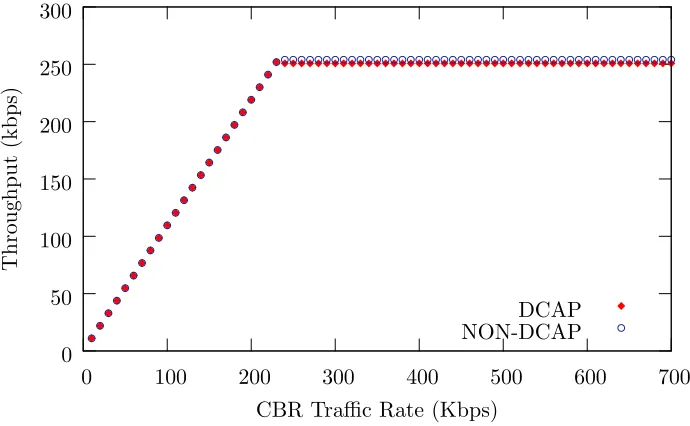
The results of test one show the throughput of the network was minimally
im-pacted by the addition of DCAP. The throughput of the network was predicted to be
nearly identical since the introduction of DCAP introduces no substantial overhead. Since
the two nodes are located on the same channel (the wireless node’s Home Channel), the
nodes will not perform any channel switching. As shown in Figure 3.3 for subtest 1.3, both
T e s t 1 .1
C h a n n e ls : 2 0 0
T e s t 1 .2
C h a n n e ls : 2 0 0
T e s t 1 .3
C h a n n e ls : 2 0 0
L e g e n d
P a c k e ts
0
C h a n n e l 0
G a te w a y N o d e
W ire le s s N o d
e
Figure 3.2: Test One: Two Nodes
0 50 100 150 200 250 300 350 400 450 500 550
0 100 200 300 400 500 600 700
T
h
ro
u
gh
p
u
t
(k
b
p
s)
CBR Traffic Rate (Kbps)
DCAP NON-DCAP
3.2
Test Two: Three Nodes
In test two, a network of three nodes was designed with all nodes in a line so the
two wireless nodes were outside of each other’s transmission range (see Figure 3.4). One
gateway node containing two network interfaces was located in between the wireless nodes.
Each wireless node had its own Home Channel, and one gateway interface was located on
each of these channels. The network contained only two available channels. Each of the
three subtests performed (2.1, 2.2, and 2.3) had different traffic patterns. The first subtest,
2.1, contained traffic going to the gateway node from the two wireless nodes. In subtest
2.2, the traffic was going to the wireless nodes from the gateway node, and subtest 2.3 had
traffic flowing in both directions.
T e s t 2 .1
C h a n n e ls : 2 0
0 1
1
T e s t 2 .2 C h a n n e ls : 2
0
0 1 1
T e s t 2 .3
C h a n n e ls : 2 0 0 1 1
L e g e n d
P
a c k e ts
0
C h a n n e l 0
1
C h a n n e l 1
G a te w
a y N o d
e
W ire le s s N o d e
Figure 3.4: Test Two: Three Nodes
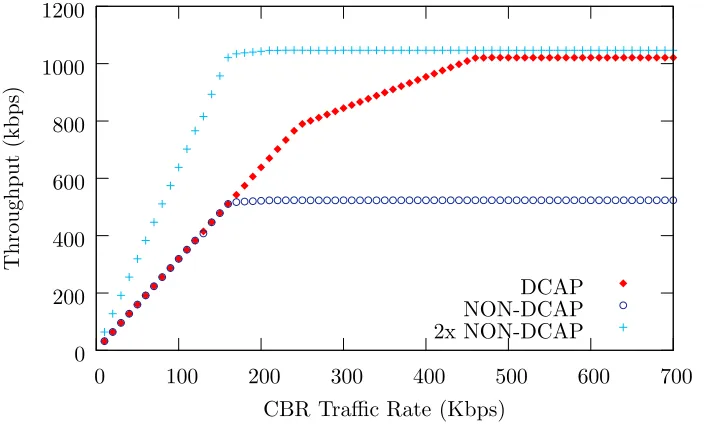
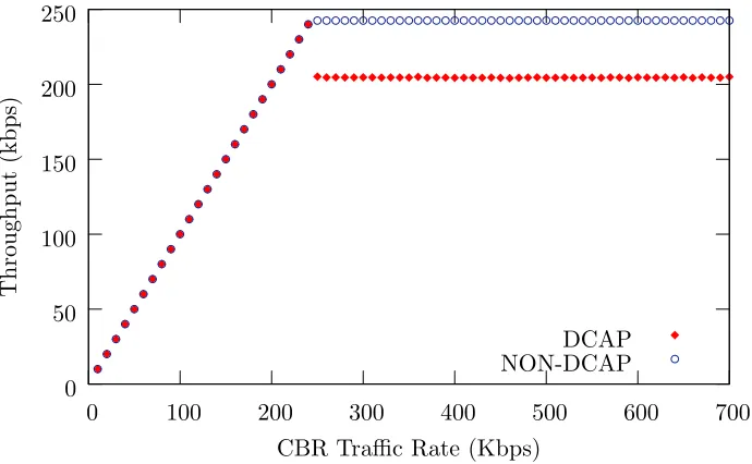
Since the DCAP network utilized two channels, DCAP’s predicted throughput
was slightly less than twice that of non-DCAP. As the graph (see Figure 3.5) for
sub-test 2.3 shows, the throughput in the DCAP network approaches twice the throughput
of the non-DCAP network, as expected. The throughput of the DCAP and non-DCAP
networks is identical as the offered load increases until the non-DCAP saturates the
chan-nel around 7Mbps. At that point, the non-DCAP throughput remains constant while the