Networks. (Under the direction of Associate Professor Injong Rhee).
There has been a recent spur of interest in the use of wireless multi-hop networks especially in the context of a replacement for traditional wired networks in small to medium-sized enterprises. However, as such networks increase in size, data rates, and number of users, it was quickly realized that contemporary congestion control protocols designed for wired networks, especially TCP, do not translate well into the wireless medium.
With TCP being so ubiquitous, it was a natural first step to take a top-down ap-proach and identify the problems that plague TCP in such wireless environments. Several key problem areas have been identified; to name a few – TCP’s reliance on losses as a con-gestion signal, TCP’s interaction with wireless routing protocols, TCP’s aggressive probing for bandwidth and self-interference between TCP data and ACK packets. As a response to these problems, the research community has proposed several enhancements to TCP, e.g. TCP-FeW [72], TCP-Veno [31], TCP-Westwood [18], TCP-ELFN [45]. Such protocols focus on improving the achievable capacity in such networks. However, as the number of such concurrent TCP flows increase, the focus has now shifted to improving thefairness in such networks. The wireless medium is shared among neighboring nodes; thus bandwidth must be allocated fairly among neighboring flows that do not necessarily share the same link. Protocols like TCP face severe unfairness or even starvation of a large number of flows [36]. A second challenge is the recent interest in exploiting the broadcast feature of wire-less networks, leading to the proposal of many creative protocols including opportunistic routing and network coding. These protocols enable the use of many diverse, yet dy-namically changing routing paths. Congestion control for these protocols using traditional end-to-end protocols such as TCP may result in too conservative rate control.
by Ajit C. Warrier
A dissertation submitted to the Graduate Faculty of North Carolina State University
in partial fullfillment of the requirements for the Degree of
Doctor of Philosophy
Computer Science
Raleigh, North Carolina
2008
APPROVED BY:
Dr. Rudra Dutta Dr. Do Young Eun
Dr. Injong Rhee Dr. Khaled Harfoush
DEDICATION
BIOGRAPHY
ACKNOWLEDGMENTS
TABLE OF CONTENTS
LIST OF TABLES . . . vii
LIST OF FIGURES . . . viii
1 Introduction . . . 1
1.1 Thesis Organization . . . 4
2 Prior Work . . . 6
2.1 TCP-variants . . . 6
2.2 Wireless Sensor and Mesh Networks . . . 6
2.3 Network Coding . . . 7
2.4 Multi-path Routing - Spatial Path Diversity . . . 8
2.5 Multi-path Routing - Temporal Path Diversity . . . 9
2.6 Cross-Layer Optimization . . . 10
3 Motivations . . . 12
4 DiffQ - Design . . . 17
4.1 Congestion control for single path routing . . . 18
4.2 Congestion control for multi-path routing . . . 21
4.3 Prioritized MAC . . . 23
5 QoS MAC . . . 24
5.1 Introduction . . . 25
5.2 Related Work . . . 27
5.3 Medium Access Mechanisms for Fairness and QoS . . . 29
5.3.1 Differentiated backoff-based schemes . . . 29
5.3.2 Beacon-based schemes . . . 29
5.3.3 Scheduling-based schemes . . . 30
5.4 MAC Modifications for ZigBee and Multihop Environments . . . 31
5.4.1 CC2420 Transceiver – Overview . . . 31
5.4.2 Large Packet Size Emulation . . . 32
5.4.3 Overhearing . . . 32
5.4.4 802.11e . . . 32
5.4.5 EY-NPMA . . . 33
5.4.6 DWOP . . . 38
5.4.7 Relative Overheads . . . 39
5.5 Implementing Fairness Policies . . . 40
5.5.1 Proportional Rate Allocation and Time Fairness . . . 40
5.5.2 EDF Scheduling in Multi-hop Networks . . . 42
5.6 Testbed Results . . . 43
5.6.1 Experimental Methodology . . . 43
5.6.2 EDF Scheduling . . . 44
5.6.3 Static Priority Scheduling . . . 46
5.6.4 DiffQ Performance . . . 48
5.6.5 Proportional Rate Allocation . . . 51
5.7 Conclusion . . . 51
6 DiffQ - Architecture and Implementation . . . 55
6.1 Overall architecture . . . 55
6.2 Interface into IP Layer . . . 56
6.3 DiffQ header format . . . 57
6.4 DiffQ scheduler . . . 58
6.5 MAC prioritization extension . . . 59
6.6 Integration with MORE . . . 59
7 DiffQ - Experimental Results . . . 61
7.1 WiSeNet Testbed . . . 61
7.2 Experimental Setup . . . 61
7.3 Multi-path congestion control . . . 65
7.4 Single-path congestion control . . . 67
7.5 Contribution of rate control, scheduling and MAC prioritization . . . 70
8 Conclusion and Future Work . . . 77
LIST OF TABLES
Table 6.1 802.11e configuration parameters . . . 59
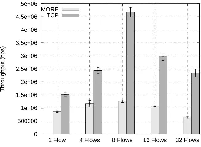
Table 7.1 Throughput of MORE and TCP . . . 64
LIST OF FIGURES
Figure 3.1 CDF of per-flow average throughput of MORE. Many concurrent MORE flows running without congestion control experience congestion collapse. . . 13
Figure 3.2 CDF of per-flow average throughput of TCP. Many concurrent TCP flows experience unfairness issues. . . 14
Figure 3.3 Average per-run total throughput for MORE and TCP. . . 15
Figure 3.4 The fairness problem of TCP in multi-hop wireless networks. We test three flows – one flow over three hops started at time 0 and the two other flows over one-hop started at seconds 45 and 70 respectively. We find that the throughput of flow 1 quickly reduces to zero as flows 2 and 3 join due to the fairness problem. . . 16
Figure 4.1 The operation of DiffQ. The thick lines represent channel accesses. According to DiffQ, nodesB and F get the channel access first as they have the largest queue differential values within their sensing ranges. . . 22
Figure 5.1 The working of Siren for nodes A, B, C and D with priorities 1,1,2 and 3 respectively is shown above. Both A and B send beacons after one CCA time.
C and D sense the beacons after two CCA times, and hence they postpone their transmissions to the next time slot. BothAandB enter the CR phase and contend for the channel. Apicks a shorter backoff and successfully transmits a packet while
B senses this packet and defers its transmission to the next slot. In the third time slot, C transmits a beacon after two CCA times which is sensed by D after three CCA times. Hence D defers its transmission whileC transmits its packet. Finally
D transmits its beacon and packet in the fourth time slot. . . 34 Figure 5.2 The expanded view of one time slot which clearly shows the PR and CR
phases.. . . 35
Figure 5.3 Figure shows how nodeA uses a higher beacon transmission power to block out potential interfering nodes for receiverB. C is a one-hop node whose transmis-sion toG would interfere with both A’s transmission and B’s reception. F and E
Figure 5.4 DWOP problem scenario in lossy networks. NodeAreserves the channel with a high priority packet using an RTS/CTS exchange. The small size of RTS/CTS allows nodes far away from A (e.g. C and D), to overhear A’s priority and enter
A’s priority in their priority cache. The consequent data packet from A informs neighboring nodes that A’s transmission is over and also advertises the priority of the next HOL packet. However, due to the higher packet loss rate caused by the large data packet size, A’s transmission to B is not overheard by C. Hence C
never knows that A has completed transmission. This causes C to defer its own transmissions needlessly. . . 38
Figure 5.5 Normalized priority resolution overhead for Siren, EY-NPMA and 802.11e with non-overlapped backoff periods with different data packet sizes. . . 39
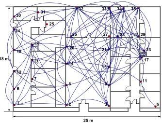
Figure 5.6 Above figure shows the 35 node mote testbed distributed across one floor of the MRC building. Lines between nodes indicate connectivity achieved with data transmission power of -5 dBm. . . 43
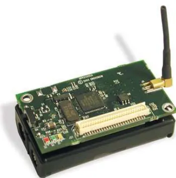
Figure 5.7 A single MicaZ node. Each node is equipped with 4K RAM, 128KB flash ROM, a 2.4 GHz ZigBee compatible radio capable of a raw data rate of 250 Kbps, and an 8 MHz CPU. . . 44
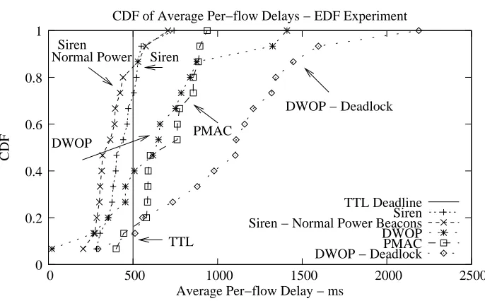
Figure 5.8 Distribution of delays in the EDF scheduling experiment. . . 45
Figure 5.9 Number of runs for each MAC where the average per-flow delay is below the EDF deadline. . . 46
Figure 5.10 Aggregate throughput for all runs where the average per-flow delay is below the EDF deadline. . . 47
Figure 5.11 Above figure illustrates the DWOP problem in lossy networks. Flows 33→ 32 → 31 and 7 → 8 → 14 are real-time flows from one of the runs in the EDF scheduling experiment. Node 3 is the source of a flow which was observed to be starved. We monitored node 3 and found that it was continuously deferring its own transmission due to perceived high priority packets in its neighborhood. The figure on the right represents the normalized fraction of time spent in deferring attributed to the constituent flow segments. About 75% of the time 3 defers due to the RTS heard from node 32 (32→31) or the CTS heard from 32 (33→32). . . 48
Figure 5.12 Average normalized per-flow throughput (with 90%) confidence intervals of high-priority flows in the static priority scheduling experiment. Note that the MACs are presented in the increasing order of normalized throughput. . . 49
Figure 5.14 Fraction of low priority flows getting starved (0 throughput) in the static
priority scheduling experiment. . . 51
Figure 5.15 Distribution of aggregate utility Plog(x) for CLO experiment. . . 52
Figure 5.16 Comparison of per-flow throughput of baseline CSMA with CLO-Siren for one specific run. Note that CSMA’s aggregate throughput is higher, but CLO-Siren gets better utility since no flow is starved. . . 53
Figure 5.17 Proportional rate allocations for DWOP and Siren compared with the ideal rate allocations for 4 and 6 sources. . . 54
Figure 6.1 Linux Netfilter hooks; DiffQ uses these hooks to capture packets from IP and reinject processed packets into IP. . . 56
Figure 6.2 DiffQ Architecture and Packet Header Format - DiffQ sits on top of IP and provides congestion control services to upper layer transport modules. It also con-trols the MAC priority of packets for scheduling and performs source rate concon-trols for the transport flows (for support of TCP, it disables TCP’s congestion control. . 58
Figure 6.3 DiffQ integration with MORE - DiffQ provides congestion control service to MORE which sits in the application layer.. . . 60
Figure 7.1 One floor of our testbed with 20 nodes. The full testbed has 46 nodes over three floors. . . 62
Figure 7.2 Soekris mesh nodes used on WiSeNet. . . 63
Figure 7.3 CDF of per-flow average throughput for DiffQ-MORE. . . 65
Figure 7.4 Average per-run fairness index of MORE and DiffQ-MORE . . . 66
Figure 7.5 Average per-run aggregate throughput of MORE and DiffQ-MORE . . . 67
Figure 7.6 Average per-run log utility of MORE and DiffQ-MORE . . . 68
Figure 7.7 Relative throughput difference between DiffQ-MORE and MORE with re-spect to path ETX. . . 69
Figure 7.8 The CDF of per-flow average throughput of TCP. It shows that DiffQ-TCP do not incur much flow starvation. . . 70
Figure 7.9 The instantaneous throughput of three DiffQ-TCP flows for the same sce-nario described in Figure 3.4. . . 71
Figure 7.11 Average per-run fairness index for single path reliable algorithms . . . 72
Figure 7.12 Average per-run logarithmic utility for single path reliable algorithms . . . 73
Figure 7.13 Scatter plot of per-flow throughputs for the 32 flow scenarios. . . 73
Figure 7.14 Average per-run jain’s fairness index for single path congestion control al-gorithms (unreliable transport). . . 74
Figure 7.15 Average per-run log utility for single path congestion control algorithms (unreliable transport) . . . 74
Figure 7.16 Average per-run aggregate throughput for single path congestion control algorithms (unreliable transport) . . . 75
Figure 7.17 Distribution of throughput of each flow when run together. . . 75
Chapter 1
Introduction
Wireless networks have proliferated significantly over the past decade – recent applications of wireless communications include habitat monitoring [90], Internet access through mesh networks [5], wireless video surveillance [61], etc. These deployments have been made possible due to several innovative research developments – on the hardware side, radio transceivers have become smaller and cheaper and on the software side, several inno-vative algorithms have been developed which exploit the features exclusive to the wireless environment. As such networks have progressively become larger in size, the applications being deployed on them are also demanding higher data rates. Hence congestion control for large scale multi-hop wireless networks is crucial to the success of such applications.
TCP is the dominant transport protocol in the Internet today, with an end-to-end approach to congestion control. TCP sources control their rates in an Additive Increase, Multiplicative Decrease (AIMD) manner, with rates being reduced on the detection of packet losses either by duplicate ACKs or timeouts. This approach works well on Internet backbone networks which predominantly consist of highly reliable wired links. However, with the advent of wireless links – first as one-hop access networks like wireless lans (WLANs) and later as full fledged multi-hop networks e.g. wireless mesh networks – it has become apparent that the TCP algorithm has finally begun to show its age. Applications using TCP over wireless networks observed significant performance problems [41, 12, 45].
bandwidth and self-interference between TCP data and ACK packets. As a response to these problems, the research community has proposed several enhancements to TCP, e.g. TCP-FeW [72], TCP-Veno [31], TCP-Westwood [18], TCP-ELFN [45]. Note that such protocols focus on improving the achievable capacity in such networks. However, as the number of such concurrent TCP flows increase, the focus has now shifted to improving the fairness in such networks.
The wireless medium is shared among neighboring nodes. The common form of media access control (MAC) is CSMA such as IEEE 802.11 where a radio transmission can affect a geographically scoped region instead of a specific receiver. In such a network, contention occurs not only among those flows that share the same links or routers, but also among neighboring flows that do not necessarily share the links. Directly applying TCP to these networks causes severe unfairness in resource usage among competing flows and this problem has been well-documented in a number of papers (see [36]).
The second major issue is the recent advances in wireless error control techniques which have completely changed the status quo and created environments which require a re-think of the way we approach the problem of wireless congestion control. The major challenge comes from the liberal use of multi-paths by schemes such as opportunistic rout-ing [17] and network codrout-ing [53], which leverage the broadcast nature of wireless networks to improve network capacity. In these protocols, packets of a single flow simply “flows” through many paths toward the destination just like a river flowing through valleys. They make possibly dynamic and local changes in routing paths adapting to dynamically vary-ing wireless link condition. Routvary-ing is also non-deterministic as it occurs opportunistically through intermediate routers thathappen toreceive packets through overhearing.
take. As the number of possible paths gets large, receiving feedback from all (possibly tem-porary) congestion incidents from various parts of the network can cause feedback implosion commonly seen in reliable multicast [26]. Protocols using TCP as end-point congestion con-trol must react to all these uncorrelated congestion signals from the network which limits the transmission rate to a very low rate, causing low resource utilization. Techniques to aggregate the feedback inside the network such as reporting only the maximum delays (e.g., ATP [15]) or minimum link rate (e.g., EXACT [20]) lead to too conservative rate control because the end-point rate control protocols must react only to the worst case condition in the network.
Congestion control over multi-path routing have also been studied in cross-layer optimization. Many existing cross-layer optimization frameworks are highly theoretical with unrealistic assumptions about wireless interference models and have too strong limitations to be applied directly to real networks. For instance, to achieve the optimal performance requires solving an NP-hard problem in general interference models. As a result, none of the existing solutions have been implemented in real systems.
In this thesis, we propose a new congestion control protocol for general purpose wireless multi-hop networks. This protocol is designed with the following informally defined goals: (1) it must support traffic carried by non-deterministic multi-path routing over pos-sibly diverse and many paths as well as single path routing. This means congestion control must be scalable to the number of paths being used, (2) congestion control is a service for diverse applications so that it should not require any changes in application operations such as reliability (e.g., coding) and application-level routing (e.g., opportunistic multi-path or single path), and (3) it must improve efficiency in resource usage to achieve high throughput and fairness in resource sharing among concurrent flows.
1.1
Thesis Organization
Congestion control for multi-hop networks has been studied extensively over the past decade. In Chapter 2, we present a survey of this work and try to put our work in the context of recent developments. In Chapter 3, we present the motivation for our work. Chapter 4 presents the DiffQ algorithm. DiffQ requires a MAC which supports prioritized packet transmissions. The most popular implementation of a prioritized MAC is the IEEE 802.11e [13] protocol which is available on most 802.11 [25] wireless cards. However, as we demonstrate in Section 5.6, 802.11e and its variants have numerous performance issues. As a result, we first conduct a performance evaluation of various MACs which support prioritized transmissions in Chapter 5.
In Chapter 6, we present the system architecture and implementation of DiffQ in an 802.11b-based mesh network. DiffQ is integrated into the Linux kernel and supports various transport protocols including UDP, TCP (without its congestion control), as well as application-level routing supported by MORE and ExOR.
In Chapter 7, we present the performance results of DiffQ in a testbed of 46 IEEE 802.11b nodes deployed over a 100,000 sq ft building. Our experiments show that DiffQ significantly improves the performance of MORE by 2 to 3 times when tested under 32 concurrent flows of MORE. The gain drastically improves with the increasing number of concurrent flows. This gain is possible because the congestion control mechanism of DiffQ avoids congestion collapse and ensures fair sharing of bandwidth among concurrently running MORE flows. The results demonstrate that DiffQ effectively handles multi-path routing used in opportunistic routing and network coding in wireless multi-hop networks. We also compare the performance of DiffQ augmented TCP-SACK and UDP with that of commonly used single-path congestion control algorithms such as SACK [70], TCP-FeW [72], and TFRC/ECN [30, 29]. TCP-TCP-FeW and TFRC/ECN are designed specifically for wireless multi-hop networks; TCP-FeW solves the capacity over-estimation problem of TCP [35] in wireless networks and TFRC is augmented with ECN [29] to remove TCP’s de-pendence on using packet losses as congestion indications. TFRC/ECN uses AQM marking as congestion indications and ignores packet losses. Our experiments show that the DiffQ augmented protocols show superior fairness properties than these protocols while achieving comparable average throughput.
Chapter 2
Prior Work
Lochert et al. [67] have compiled a comprehensive survey of wireless congestion control protocols. In this section, we build on top of this survey by describing recent advances, especially opportunistic routing and network coding, and put them in context with prior work.
2.1
TCP-variants
Lochert et al. [67] gives an extensive overview on proposals for improving TCP performance in wireless multi-hop networks. Many involve retaining the end-point conges-tion control of TCP with slight modificaconges-tions in router funcconges-tionality to give notificaconges-tions about link failures (e.g., [45, 66, 95, 57]) and congestion states (e.g., [29, 94, 99, 33]) or to use other congestion metrics such as delays (e.g., [32, 15, 18]) or explicit rate calculation (e.g., [102, 20, 89]) measured inside routers. Some (e.g., [34, 72]) fix the problems of TCP over-estimation of path bandwidth by reducing the source rate of TCP. These solutions however ignore the fairness issues arising from radio interference.
2.2
Wireless Sensor and Mesh Networks
that perform congestion mitigation, in that they aim to detect and reduce the effects of congestion. As noted by Rangwala et al. [81] this goal is slightly different from congestion control, where the aim is to regulate rates of all sources to achieve some optimal operating point.
Both Fusion [47] and CODA [93] use queue sizes to measure the degree of con-gestion. CODA goes one step further and also uses the MAC utilization at each node as a congestion indicator. Fusion also rate-limits the transit and self-traffic to achieve a per-node notion of fairness. Interference-aware Fair Rate Control (IFRC) [81] differs from the previous approaches by being a full-fledged congestion control protocol. In IFRC, nodes rely on the routing tree rooted at the sink node for congestion control. Each node knows the child nodes pumping data to itself, as well as its own parent and sibling nodes within radio range. This information is used to calculate the max-min fair rate for that node. This rate is then propagated down the routing tree. Again, congestion is detected from increasing queue sizes, and sources control their transmission rate by AIMD rate control. On similar lines, algorithms like C3L [82] and TAP-fairness [36] have been proposed for mesh networks where the specific topology and flow patterns in the network are used to calculate the fair share of rates for each flow explicitly.
DiffQ shares some aspects of the above algorithms. For instance, it uses queue sizes as a measure of congestion, and a prioritized MAC to flush a full queue. Also, like in IFRC, sources control their rate in an AIMD manner. However, the exact interaction of source rate control, queue size based scheduling and MAC prioritization is different in DiffQ. It is this difference that makes DiffQ more flexible and allows it to support general traffic patterns.
2.3
Network Coding
Note that network coding as performed in this manner does not alter the routing path being used. Hence it is possible to combine it seamlessly with TCP and other single path congestion control algorithms. It is in fact highly suited to TCP due to its bidirectional traffic pattern – consider nodes A, B and C in a chain topology. A transmits data to C via B. Node B can code TCP data packets being forwarded to C and TCP ACK packets being forwarded from C to A into the same packet. Since A and C already have the packets they transmitted in their cache, they can decode the packet they need, i.e. the TCP ACK and data respectively from the coded packet transmitted by B.
Along this line, Katti et al. proposed COPE [54] where they integrate TCP and XOR based network coding. The impact of network coding on TCP is studied in more detail by Huang et al. [46]. They found that if intermediate nodes delay their packet transmissions by a small time period, coding opportunities increase, but at the same time TCP throughput suffers due to increase in RTT. A per-node delay of 1-2 ms is advocated by the authors on small mesh networks where they observe a performance gain of 50-70% in throughput. This is of course an experimental result, and more analysis of the interaction between TCP and network coding needs to be done in the future. Also note that network coding as performed by COPE is a form of inter-flow coding – packets from different flows are coded together. Hence unidirectional flows, and even bi-directional flows with asymmetric network paths will not benefit from this form of network coding. In Section 2.5 we will study an intra-flow network coding technique which benefits unidirectional flows and does not rely on network paths to be symmetric.
2.4
Multi-path Routing - Spatial Path Diversity
Most congestion control studies for multi-path routing are on wired networks with the perspective of load balancing [65, 96, 55]. Load balancing is especially important in wireless networks to improve capacity. This is because routing algorithms usually choose the best links for routing, causing most routes to go through a set of nodes which happen to be well-connected. This set of nodes carry a disproportionate amount of traffic compared to the rest of the network. Multi-path routing was proposed as one way to counter this problem by performing load-balancing among available spatially diverse routing paths.
load-balancing, since most of the K shortest paths actually lie close to each other, thus increasing self-interference. Approaches like SMR [59] and AOMDV [68] which find node-disjoint and link-node-disjoint paths may also face the problem of self-interference. Clearly, achieving effective load-balancing requires findingK disjoint and interference-free paths in a wireless network. Popa et al [79] achieve this by using location information and geographic routing. In their solution, instead of selecting direct shortest paths toward a destination, packets are forwarded along curves. This mitigates the self-interference problem. Traffic is split locally at intermediate nodes as well as the source. The source node performs rate control along each path. Although very effective at load-balancing, this approach is limited due to the requirement of geographical information.
As the number of independent routes increase, the congestion control algorithm has two options: aggregate the path statistics from multiple routes or maintain distinct state on a per-path basis. Maintaining per-path statistics, e.g. MPLOT [84] does not scale well. Aggregating path statistics causes two problems. First, feedback from multiple uncorrelated temporary events in the wireless network may overwhelm the sender, similar to thefeedback implosion problem [26] in multicast. Second, the sender will conservatively tune its rate to the worst case among the available paths (since majority of the aggregated congestion events would be due to the worst path), leading to reduced performance.
2.5
Multi-path Routing - Temporal Path Diversity
Wireless being a broadcast medium, packets transmitted by a node may be over-heard by its neighbors, who may help in forwarding it. This basic principle is used in opportunistic routing [17] to improve network capacity. Packets traverse severaltemporally existent network paths on the way to the destination. The challenge is to ensure that among all nodes that overhear a packet, the node closest to the destination is the one who for-wards it. This is achieved in [17] by maintaining a strict MAC scheduler for all intermediate nodes between the source and the destination. To decouple the MAC from routing, Katabi et al. [19] propose MORE where opportunistic routing is combined with intra-flow network coding. In MORE, intermediate nodes randomly code overheard packets before forwarding them. Coding prevents forwarding nodes from transmitting redundant copies, since each packet is generated from the local cache of the node’s overheard packets.
unpre-dictability in wireless resource usage. The path taken by the packet is no longer known to the source, and hence conventional wired multi-path congestion control algorithms effectively break down in such environments.
2.6
Cross-Layer Optimization
DiffQ is inspired by theoretical cross-layer optimization approaches, especially dif-ferential backlog backpressure, first proposed for wireless multi-hop networks by [58]. There have been many follow-up studies (e.g., [77, 22, 80, 63, 75, 76]) that use the framework to jointly optimize various components of the protocol stack including scheduling, routing, congestion control, multi-receiver diversity and coding. However, these studies use interfer-ence models such as the one-hop interferinterfer-ence model to avoid solving an NP-hard problem for the optimal solution. But the interference in real wireless networks commonly affect a multi-hop neighborhood. More important, most of them require the network to be suf-ficiently loaded to offer the optimization in order to measure queue size differences. In these solutions, when the network is lightly loaded, packets are sent almost everywhere randomly to “create congestion”. This incurs high transport delays (see [97]). Since all these solutions optimize for maximizing a function of throughput, the high delays do not affect their optimality. But in practice, delay is an important issue for Internet applications (e.g. web, instant messaging) whose requirement is not real time, but fast response time is a key for their success. Because of combination of the above factors, we do not find any implementation of these solutions in real systems.
Recently, Neely et al. [77] have combined opportunistic routing, and several other approaches [80, 56, 27] have combined network coding into the cross-layer framework. Note that the main goal in such proposals is to manipulate the congestion control, routing, MAC and/or network coding components together to optimize a particular utility function. This differs from DiffQ’s goal, which is to provide congestion control as aserviceto an application without requiring application-specific modifications, e.g. in the case of MORE, DiffQ takes as input the potential forwarders for a node and performs congestion control among them. Hence the performance of DiffQ when combined with such applications would be lower than that obtained by cross-layer optimization approaches.
Chapter 3
Motivations
In this chapter, we motivate the need for DiffQ by studying two key congestion-related performance problems observed in wireless multi-hop networks.
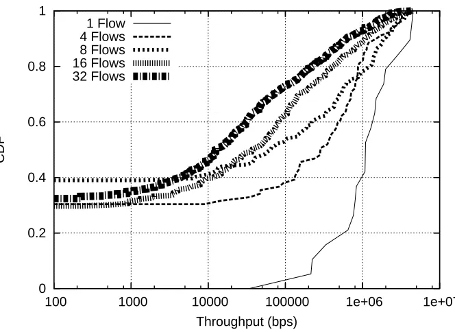
The following results are derived from a testbed network of 46 indoor IEEE 802.11 nodes deployed over a three story building of 100,000 sq. ft. space (more detailed description in Section 7). Tests are conducted between random pairs of source and destination nodes The maximum number of hops in our testbed is around 6 or 7 hops. MORE is representative of the multi-path schemes which can benefit from using DiffQ. In each experiment, we increase the number of concurrently running MORE flows. We repeat each experiment 20 times. Figure 3.1 (a) shows the CDF of per-flow throughput of MORE as we increase the number of flows in each run. We do not employ any congestion control for this experiment.As the number of flows increase, we observe that the number of starved flows increases quickly. With 32 flows, over 50% of flows are completely starved.
0 0.2 0.4 0.6 0.8 1
1000 10000 100000 1e+06
CDF
Throughput (bps) 1 Flow
4 Flows 8 Flows 16 Flows 32 Flows
Figure 3.1: CDF of per-flow average throughput of MORE. Many concurrent MORE flows running without congestion control experience congestion collapse.
competing flows; while a few flows get a disproportionally larger amount of throughput, many flows are starving.
0 0.2 0.4 0.6 0.8 1
100 1000 10000 100000 1e+06 1e+07
CDF
Throughput (bps) 1 Flow
4 Flows 8 Flows 16 Flows 32 Flows
Figure 3.2: CDF of per-flow average throughput of TCP. Many concurrent TCP flows experience unfairness issues.
bandwidth. The situation escalates to the eventual starvation of the first flow.
0 500000 1e+06 1.5e+06 2e+06 2.5e+06 3e+06 3.5e+06 4e+06 4.5e+06 5e+06
32 Flows 16 Flows
8 Flows 4 Flows
1 Flow
Throughput (bps)
MORE TCP
h i j k l m n o { j w G z { j w { j w { j w { j w G k m s v ~ GX m s v ~ GY m s v ~ GZ
(a) A test scenario; dotted circles represent interference ranges.
10M
1M
100K
10K
0 20 40 60 80 100 120
Throughput (bps)
Time (seconds) Flow 1
Flow 2 Flow 3
(b) Instantaneous throughput of three TCP flows
Chapter 4
DiffQ - Design
In this chapter, we present the design of DiffQ for single and multi-path routing algorithms.
In DiffQ, each node maintains a queue for each destination of the flows whose packets it forwards. At the reception of a packet, it can be delivered to the application if the node is the destination or placed into its destination queue in the FIFO order for forwarding to next hops. The queue information and states in a node are soft-state – a destination queue may disappear when there is no packet for that destination. We define a neighbor by its symmetric relation; if a node A is a neighbor of another node B, then
B is also a neighbor of A and we say there is a link between the two nodes. In wireless networks, asymmetric links are common. However, most wireless routing protocols rely on symmetric links where at least probes (e.g., ETX) can be acknowledged. Any ETX-metric based routing protocols including OLSR [49], SRCR [16], ExOR [17] and MORE [19] use this property implicitly.
4.1
Congestion control for single path routing
We assume that routing is determined by the underlying routing layer and each node knows its next hop forwarding nodes for destinations of received packets. The per-hop congestion control algorithm of DiffQ works as follows. Let us denote Qi(d) to be the destination queue for destinationdin nodei. For each destination queueQi(d), it maintains the following information every time a new packet is received or overheard from a neighbor destined to destination d. Suppose that j is the next hop node toward the destination d
from nodeiaccording to the underlying routing layer.
QDi(d) =|Qi(d)| − |Qj(d)| (4.1)
where|Qi|is the size of queueQi. We callQDi(d) thequeue differentialor differen-tial backlogof destinationdat nodei. For the head-of-line (HOL) packet of each destination queue, we assign a priority which is used for resolving MAC contention in IEEE 802.11 when it is transmitted. At each time that a new packet needs to be transmitted, nodeievaluates the priority of the HOL packet of each queue based on its queue differential – the larger the queue differential, the higher priority the packet gets. Since we can only support a finite number of priority levels, we quantize the queue differential value. For simplicity, we use a linear quantization by dividing the queue differential by a fixed interval that is set by dividing the maximum queue size by the number of supported priority levels. Node i
chooses the HOL packet of the highest priority among all HOL packets in its destination queues, for transmission next time. Ties are broken arbitrarily. The priority of the HOL packet is used to resolve the channel access. We modified the IEEE 802.11 MadWiFi driver to support prioritized access among competing nodes by adjusting the contention window sizes and AIFS. More details are given in Section 6. It ensures higher chances for channel access to the node with a higher priority packet for transmission. The pseudo code for the source and forwarder are given in Source Rate Control() and Forwarder Algorithm() respectively.
designed. In our study, we evaluate AIMD or logarithmic adjustment (which optimizes for the sum of log of per-flow throughput) as used in [23] or [83]. Our pseudo-code of DiffQ below describes a version of AIMD.
Algorithm Source Rate Control()
1. F = Destination of flow originating at this node 2. qlen ←|Qi(F)|;
3. if qlen >QUEUE THRESH 4. rate = rate/β; 5. else
6. rate = rate + α;
Algorithm Forwarder Algorithm()
1. ∆←Number of priority levels supported by MAC; 2. D←Maximum per-destination queue size;
3.
4. Flow Scheduling
5. F←argmaxdQDi(d); 6. P←HOL packet ofQi(F); 7. P.priority←MAX(⌈QDi(F)
D ∆⌉, 0); P.qlen ←|Qi(F)|; 8. Transmit P;
9.
10. On receiving packet P from local application
11. Encapsulate P with DiffQ header; 12. if P is the first packet
13. Create flow entry for P’s destination; 14. F ←Destination of P;
15. EnqueueP intoQi(F); 16.
17. On reception of packet P from node j
18. F ←Destination of P; 19. if F is this node
22. else
23. if No flow entry exists forF
24. Create flow entry forF; 25. if node j is the routing next-hop for F
26. QDi(F) ←|Qi(F)| − |Qj(F)|;
27. else
28. Enqueue P intoQi(F);
We now provide the rationale for the above algorithm. DiffQ looks a lot like a scheduling algorithm. But it also has a unique way of applying backpressure. Suppose that a flow f is forwarded through a chain of nodes X,Y, Z and so on in that order, and suppose the size of the destination queue of flow f at node Z is reducing as somehow Z
can forward the packets of f fast to its next hop. Then it will cause the queue differential at node Y to increase. This has effect of increasing the forwarding rate at nodeY because the channel access priority increases with the queue differential. AsY gets more prioritized access,Xwill be waiting and its queue builds up. AfterY’s queue gets depleted, then again
X’s priority increases because its queue differential against Y’s queue is rising, and then
X will have a higher chance to the channel next. For the opposite case, suppose that Z’s next hop is congested soZ cannot forward its packets. ThenZ’s queue will build up while increasing its priority. In the mean time, Y’s queue differential will reduce because Z’s queue is increasing and allows less chance accesses for Y. Consequently, Y’s queue builds up. This backpressure will propagate to the source ifZ’s congestion does not resolve soon enough.
Through backpressure, the size of a destination queue in a node reflects the ag-gregated condition of all paths from that node to the destination: small queues represent good path conditions on the paths as packets can leave the queue fast and indicate that the paths may be able to support additional load. Thus, when the destination queue size of the next hop node gets smaller, the priority of the flow being forwarded to that node gets increased, ultimately increasing the flow rate to that node. On the other hand, large queues represent bad path conditions from that node to the destination. This reduces the queue differential of the preceding hop node which reduces its transmission. This condition propagates until the backpressure reaches the source unless the situation improves soon.
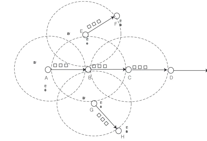
al-though those flows do not share the same routers or links. When a flow is continually denied of transmission at a node in a network path due to contention from its neighbors, then its queue size at that node will increase. This has an effect of increasing the queue differential for that flow at that node, and thus its channel access priority. Consider the scenario in Figure 3.4. As the one-hop flows send at a high rate, the first flow continues to be denied of channel access. In DiffQ, the destination queue of node B will increase and eventually, get a higher priority than the nodes with single-hop flows (E and G). Thus, B
will be allowed to forward the packets of flow 1. DiffQ ensures the nodes with more conges-tion to have a higher channel access priority so that they can relieve the congesconges-tion faster before the backpressure reaches the source. This feature allows DiffQ to enforce fairness among competing flows in wireless multi-hop networks.
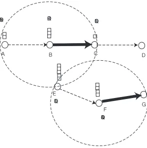
DiffQ is different from the queue occupancy based technique used in [48, 47] which sets the contention window size inversely proportional to the queue size, thus giving a higher priority to a node with a larger queue. While it also provides more congested nodes to send packets fast, the difference comes when an area is congested and many neighboring nodes are congested together. In that situation, the queue occupancy scheme allows the node with the largest queue to send packets first whether or not its next hop is congested or not. Thus, it is not clear whether those transmissions will relieve congestion. With DiffQ, those nodes with the largest queue differential make the first transmissions, allowing transmissions to occur always to the direction where congestion can be relieved. This difference is illustrated in Figure 4.1 where nodeEhas a largest queue. According to the queue occupancy scheme,
E will get the highest channel access priority. But in this case, E’s transmission only adds congestion already occurring in nodeF. But in DiffQ, nodes B and F get a channel access first as they have the largest queue differential values within their sensing ranges. This relieves congestion from the locations where it first happens and also backpressure quickly propagates back to the up-stream nodes.
4.2
Congestion control for multi-path routing
h i j k l m n x k Gd GY x k Gd GT
X xkGdGX
x k Gd GX x k Gd G[
h i j k
l m n x k Gd GY x k Gd GT
X xkGdGX
x k Gd GX x k Gd G[
Figure 4.1: The operation of DiffQ. The thick lines represent channel accesses. According to DiffQ, nodesB andF get the channel access first as they have the largest queue differential values within their sensing ranges.
nodes receiving that packet may become the next forwarding routers.
Existing opportunistic routing protocols use source-based routing where each packet contains information about the set of candidate forwarding nodes in the network. This means that at each node i, we can narrow down the possible set of forwarding routers by taking the intersection of the candidate forwarding router list in a forwarded packet p and the one-hop neighbors of that node. Let us call that intersection Fip. We assume that each packet provides the candidate forwarding list. This is not a difficult requirement as most multi-path routing algorithms such as MORE and ExOR use source routing. This assumption requires information sharing between routing and congestion control, but does not require changes in the operation of routing algorithms.
When evaluating the priority of an HOL packet p with destination d, each node
minimum of such queue differential values. We use that value for setting the priority of that packet at nodei. The following defines this operation.
QDi(d) = min j∈Fip
{|Qi(d)| − |Qi(d)|} (4.2)
Node i schedules for transmission the packet with the highest priority (i.e., the maximum queue differential) among all HOL packets and the priority of that packet is used by the MAC layer to schedule the transmission. Each node schedules its transmission based on the worst case next hop router. If there is a queue buildup at any next hop inFip, then the priority of packet p gets reduced and thus that packet will get a lower channel access priority, which effectively reduces the transmission rate of the flow packetpbelongs to. This approach is conservative because the packet may not be received by that worst case next hop.
4.3
Prioritized MAC
Chapter 5
QoS MAC
DiffQ requires a MAC which supports prioritized transmissions. There exists a rich history of literature on MACs capable of prioritized transmissions. As part of the design process of DiffQ, it is important to pick and choose the “best” MAC which performs this function. Surprisingly, we find no comparative study of such MACs in literature. The core reason for this is as follows. In response to various MAC layer fairness and QoS 1 issues, the wireless community have come up with numerous “point solutions”, with one-to-one comparison of their solution with existing MACs for the specific fairness model they target. Such solutions are closely tied to a particular fairness model, making a cross-model comparison of MACs difficult.
However, with some tradeoff of flexibility and efficiency, many of these MACs can be made relatively free of a a specific fairness model. This decoupling of the MAC from the fairness model is desirable because it allows objective testing of the MAC under different fairness models and also allows independent evolution of fairness policies and research into medium access issues. Hence, in this chapter, we take a brief detour from our main theme – DiffQ, and focus on a systematic evaluation of various MACs for their support of prioritized transmissions. We find that the ability to prioritize packet transmissions in the MAC is a desirable property not just for DiffQ but also to implement several different fairness poli-cies like proportional rate allocation, EDF scheduling, proportional fairness and temporal fairness.
1
5.1
Introduction
One of the frequently cited problems of current wireless networks is related to lack of fairness and QoS. The reported problems of MAC include, to name a few, starva-tion [86, 39, 99], priority inversion [100], inequitable allocastarva-tion of bandwidth [99], lack of QoS support [51] and multi-rate LAN unfairness [43]. The research community has come up with several novel solutions [86, 100, 51] to such problems. The common thread among such solutions is that they often require altering the MAC protocol significantly to achieve the authors’ notion of ”fairness”, in effect embedding a fairness policy into MAC. Clearly, this makes them ”point solutions”, wherein the proposed changes to MAC proposed for one so-lution are incompatible with those for other soso-lutions. To address this issue, Nandagopal et al. [73] propose a general analytical framework to allow automatic generation of MAC layer algorithms tailored to specific utility functions. In addition, extensive prior work [21, 64] on cross-layer optimization optimizes MAC functions to support a specific predefined utility function. However, note that in their work, each specific instance of a MAC algorithm is still specific to a fairness policy (or a utility function) used to generate it, and may not be used to support other fairness policies.
One main reason behind this lack of a comprehensive evaluation study is that most of the cited solutions [86, 100, 51, 52] require significant changes to MAC layer which were not possible to be implemented on current commercial radios. This is because efficiency considerations make most of the MAC layer functions in current radios be performed in firmware which is difficult to modify. This limitation forces even the one-to-one comparison of most cited solutions with existing work for a specific fairness policy to be limited to simulation. In the process significant real-world issues such as system latency, ambient channel noise, time synchronization issues, wireless channel errors, specific radio limitations such as minimum/maximum packet sizes etc. are simply glossed over. To some extent, this problem has been mitigated by the development of Software Defined Radios (SDRs) [3], which allow all components of the radio (including PHY modulation) to be specified in software. However the prohibitive per-unit costs of SDR radios make it difficult to be used for large testbed deployments. In this chapter, we address this issue by conducting an extensive experimental evaluation of existing MACs which provide fairness support in a real multihop wireless testbed environment.
Our methodology is as follows. We first survey existing work on fairness issues in single/multihop wireless environments and their corresponding proposed solutions. A com-mon technique to construct mechanisms for implementing various fairness policies is to (1) assign priorities to data packets, (2) manipulate these priorities dynamically to implement a specific policy dictated by applications, and (3) ensure channel access to be ordered in terms of the priorities. Several schemes [52, 51, 87, 92] follow this approach where fairness mechanisms are supported bypriority resolution (PR) – the mechanisms to implement the prioritized access of packets. We classify such MACs supporting PR into three categories based on the way they perform PR, and identify three representative schemes for each of the three categories.
1. Differentiated backoff based schemes, represented by 802.11e [13, 60].
2. Beacon-based schemes represented by EY-NPMA [88, 100, 11].
3. Scheduling-based schemes represented by DWOP [51, 52].
This radio is different from contemporary 802.11 radios in that it exposes a considerable amount of functionality such as clear channel assessment (CCA), transmission power and frequency control, etc. to software while still maintaining a raw bitrate of 250Kbps. The implementation of the above MACs on such a radio for multihop environments is a significant engineering and design challenge since it is important to make sure that our design decisions do not affect the experimental results and that the conclusions are valid not just for the CC2420 radio but also for other CSMA-based radios. The implementation of EY-NPMA for multi-hop environments is particularly difficult as it is designed only for wireless LAN single-hop networks and thus does not provide any mechanisms for hidden terminals. We extend EY-NPMA for multihop environments and call our extension Siren. In the next step, we identify and implement a list of commonly used fairness policies including static priority, temporal fairness proportional fairness and earliest deadline first (EDF) on top of these three MAC protocols. Finally we compare the performance of these MAC protocols in enforcing these fairness schemes on our 30 node multihop wireless testbed.
The rest of the chapter is structured as follows. Section 5.2 contains the related work. In Section 5.3 we describe the three MAC protocols we implement, while in Section 5.4 we present implementation details on the CC2420 ZigBee radio. In Section 5.5 we describe the fairness schemes we use for comparison. In Section 5.6 we present experimental results and we conclude in Section 5.7.
5.2
Related Work
Substantial research exists on the individual components of a fairness control framework i.e. fairness policy, PR, and medium access. However we will focus only on the PR scheme in this section. Priority resolution has been achieved in the MAC layer by vari-ous means. Broadly, they can be classified into three approaches – beacon based [88, 11, 100] or backoff based [13] or scheduling based [52, 51]. This bifurcation can be traced back to the original two competing standards for the wireless MAC – 802.11/802.11e [13], which uses a differentiated backoff strategy, and HIPERLAN/1 [11] which uses beacons (the scheduling-based algorithms came later).
prioritized access to the channel. Absolute service differentiation (where high priority traffic is never interfered by lower priority traffic) can be achieved in IEEE 802.11e by assigning
CWmin of lower priority classes to be larger thanAIF S+CWmaxof higher priority classes. Vaidya et al. propose a PR scheme, BTPS [100] (Busy Tone Priority Scheduling) supporting two priority levels. In this scheme, nodes are required to listen on three channels during idle periods – a data channel and two narrow-band busy-tone channels. A node with a backlogged high priority packet transmits a busy tone signal (BT1) every M slots. Neighbors that hear BT1 will forward this signal to the node’s two-hop neighbors on a different band (BT2). The node’s two-hop neighbors with backlogged low priority data that hear BT2 will defer their transmissions. This ensures the transmission of high priority packets. BTPS solves the hidden terminal problem effectively, but requires nodes to listen on multiple channels during idle periods. It is also constrained to two priority levels.
In black burst contention [88, 85], nodes with backlogged packets first wait for a short time period and then transmit small pulses of energy or black burstswhich serve to “jam” the channel. The length of a black burst is an increasing function of the priority of the backlogged packet and/or how long a node has been waiting for access to the channel. After transmitting the black burst, a node observes the channel for a short period of time to check if any other node is transmitting a longer black burst. If not it will transmit the data packet.
Kanodia et al. propose a scheduling-based PR algorithm for multihop wireless networks [51, 52]. In this scheme, nodes piggyback their priorities onto RTS,CTS, DATA and ACK packets. By overhearing such packets, nodes become aware of the priorities of the nodes in their neighborhood. This information is then used to co-ordinate channel access so that the order of packet transmissions agree with the order of priorities among the nodes. Since both schemes rely on overheard information, their performance degrades in lossy channels.
5.3
Medium Access Mechanisms for Fairness and QoS
We classify MAC schemes into three categories based on the manner in which they perform PR – (a) differentiated backoff-based schemes,(b) beacon-based schemes, and (c) scheduling based schemes. In this section, we describe these categories and their represen-tative schemes used for our evaluation.
5.3.1 Differentiated backoff-based schemes
In such schemes, nodes access the channel with a backoff-period which is a function of the priority of their head-of-line packet, e.g. a node A with higher priority2 will access the channel with a shorter backoff compared to neighboring node B with lower priority. This ensures that A captures the channel with high probability compared to B, with the exact probability of channel capture being a function of the relative backoff periods of A
and B. IEEE 802.11e and its numerous variants [13, 60] fall in this category. Note that the original standard defines 4 priority levels with varying but overlapping backoff periods for each priority. This allowed lower priority nodes to sometimes capture the channel in the presence of high priority nodes, or priority inversion [100]. In order to achieve absolute prioritization, where the higher priority nodes always capture the channel earlier than lower priority nodes, Aad et al. [14] propose having non-overlapping backoff periods for each priority, i.e. DIF Si = DIF Si−1+CWi−1, where CWi is the backoff window for priority leveli. We use this version of 802.11e for our evaluation.
5.3.2 Beacon-based schemes
In beacon-based schemes, nodes rely on short bursts of energy to inform their neighbors of their priority. The actual priority is encoded in the length of the beacon (e.g. black burst [88], prioMAC [85]) or the time (e.g. EY-NPMA [11]) at which they are sent. A subset of such schemes also rely on an additional channel to send beacons, (e.g. BTPS [100]). We focus our evaluation on EY-NPMA which uses short beacons sent at pre-defined moments in time to encode priority information. The reasoning for choosing EY-NPMA is twofold. First, encoding the priority in the length of the beacon wastes
2
For brevity, we will abuse terminology and refer to ”nodes with head of line packet priorityi” as ”nodes
energy. Second, using a separate channel for beacon transmissions is not possible in most contemporary radios which have only a single transceiver.
We refer the reader to the original EY-NPMA paper [11] for full details on its working. We give a brief description of its working. In EY-NPMA, each node goes through a PR phase followed by a contention resolution (CR) phase. The PR phase is as follows. As soon as the channel becomes idle, a node with a back-logged packet with priorityiwaits foribeacon periods which is defined to be the time to fully transmit a shortbeacon. At the end of i beacon periods, if the channel is idle, the node transmits the beacon and enters contention for the medium. However, if it hears any beacon transmission prior to the i
beacon periods, then it recognizes that a higher priority transmission is pending and defers its own transmission. If there exist more than one node with the same highest priority, they will all transmit beacons simultaneously and will enter the CR phase together. At the end of the PR phase, one or more nodes with the highest priority within two hops are left in contention, and they contend for the medium in the CR phase.
5.3.3 Scheduling-based schemes
In scheduling-based schemes, nodes disseminate priority information well before the actual packet transmissions and then co-ordinate their transmissions in such a way that the order of packet transmissions matches the advertised priorities. Distributed priority scheduling [51] and DWOP [52] follow this scheme. They are similar in the way they collect priority information: nodes piggyback their packet priorities onto RTS, CTS, DATA and ACK messages, which are overheard by neighbors. Thus each node builds a database of HOL (head-of-line) packet priorities of all its neighbors within a two-hop communication range. RTS and CTS messages of a node inform its immediate neighbors and potential two-hop interferers respectively about its HOL packet priority. DATA and ACK messages inform the neighbors that the packet has been successfully transmitted so that they may update their priority database. In addition, DATA and ACK messages also inform neighbors about the priority of the next packet in its queue.
corresponds to their HOL packet. We choose DWOP as our representative scheme due to this priority resolution mechanism as it provides the absolute prioritization property seen in our version of 802.11e (Section 5.3.1) and EY-NPMA. As we shall see later in Section 5.5, absolute prioritization allows a simplified implementation of various fairness policies.
5.4
MAC Modifications for ZigBee and Multihop
Environ-ments
We modify 802.11e, EY-NPMA and DWOP MACs to use them for multihop wire-less environments under the CC2420 radio. In this section we describe how each protocol is modified. Although the details are to some extent CC2420-specific, we believe that similar issues appear for other CSMA-based radios like commercial off-the-shelf 802.11 radios. Be-fore going into specific details for each MAC, we first give a brief description of the CC2420 transceiver.
5.4.1 CC2420 Transceiver – Overview
The MicaZ [9] sensor node contains the CC2420 [2] transceiver which is a Zig-Bee [10] compatible radio. It has a link speed of 250Kbps, resulting in a per-byte transmis-sion time of 32us. It supports 8 different transmistransmis-sion power levels ranging from a minimum of−25 dBm (<10µW) to a maximum of 0 dBm (1 mW). It contains two buffers of size 128 bytes each for outgoing and incoming packets respectively. Packets placed in the outgoing buffer need to strictly adhere to the ZigBee packet format, else they are dropped.
The ZigBee [10] standard specifies the minimum PHY layer header of 5 bytes (4 bytes preamble and 1 byte synchronization), a MAC layer header of 9 bytes and 2 bytes of CRC. This implies that the minimum packet size with no payload in CC2420 is 16 bytes. Also, the standard specifies that the maximum packet size (including PHY, MAC headers, CRC and payload) is restricted to 128 bytes.
When the link-layer ACK is disabled, CC2420 does not send ACK for received packets and leaves this responsibility to higher layers.
5.4.2 Large Packet Size Emulation
The maximum packet size of CC2420 is 128 bytes which is highly restrictive com-pared to commercial 802.11 radios with MTU of 1500 bytes. To overcome this limitation, we maintain avirtual packetat the MAC layer in which the transmission of larger packets is emulated. The size of a virtual packet is set toXtimes 128 bytes. For every data packet of size 128 bytes received from the upper layers, the MAC driver retransmits the same packet
X number of times. The receiver counts the number of CRC-valid copies of a packet it receives. If it receives X copies of the same packet, it will send ACK. Otherwise it will silently discard all copies of the packet. The sender, after sendingX copies, waits for ACK. If it does not receive ACK, it will signal a failure to the upper layer, and try again. This emulates closely the behavior of a packet of size 128×X bytes. In our experiment, we set
X to 3 for an emulated packet size of 384 bytes.
5.4.3 Overhearing
CC2420 disables overhearing when the link layer ACK is enabled. However, over-hearing is an important requirement for several of the fairness policies which we shall dis-cuss in detail in Section 5.5 where overheard information is used to decide packet priorities. Hence, we modified the default MAC driver for CC2420 to send MAC-level ACKs, and disabled the automatic link-level ACK feature of CC2420. We verified that this does not cause any appreciable loss in channel efficiency.
5.4.4 802.11e
an error and takes an appropriate error handling action. Hence the radio does not perform the CCA continuously in the transmit mode. This makes it difficult to pause and resume backoff timers based on the activity on the channel.
To get over this limitation, we do not follow the 802.11e standard of pausing backoff timers. In our implementation of 802.11e, which is called PMAC, when a node has a packet to transmit, it takes a random backoff. During the backoff period it does not check the channel. At the end of the backoff period, it will issue the STXONCCA command to the PHY. If it receives an error because the channel is busy, the node will take another random backoff. Otherwise the PHY will begin transmission.
PMAC uses non-overlapping backoff windows to support absolute prioritization. Despite this, it is still possible to have priority inversions if the backoff window is paused. To see why, consider two nodes A and B, with A having a higher priority than B. A
will naturally use a shorter backoff and will access the channel multiple times. However, during each channel access, there is some small channel idle time duringA’s backoff period. During this period,B’s backoff timer keeps counting down since the timer resumes during channel idle times and pauses during channel busy times. Hence eventually B will access the channel with a shorter backoff thanAcausing a priority inversion. Thus by not pausing backoff timers and forcing B to take a new backoff every time, PMAC completely avoids priority inversions.
A second issue with 802.11e is the use of exponentially increasing backoff timers. In the standard, if a node’s backoff timer expires, it checks the medium and if it is still busy, it doubles the backoff window and takes another random backoff within this window. However, PMAC needs to support several priority levels and supporting multiple exponential increases in the backoff window leads to large backoffs for each priority level. This greatly increases overhead for each priority level. As we shall see in Section 5.4.7, even while using a fixed window without exponential backoffs, PMAC still incurs high overhead since every priority level requires one backoff window. Hence we choose to use fixed backoff windows for PMAC.
5.4.5 EY-NPMA
time-synchronization among neighboring nodes. We refer to this modified protocol asSiren to differentiate it from EY-NPMA for the rest of this section. In Siren, time is slotted.
Note that the overhead incurred in the PR phase of EY-NPMA is the time taken for a beacon transmission times the number of priority levels supported. Clearly, a smaller beacon size incurs less overhead. Early radios (e.g. CC1000 [1]) support bit streaming which can be used to construct extremely small beacons. However the new generation of packetizing radios (e.g. CC2420 [2], most commercial 802.11 radios) does not support bit streaming and allows only valid packets with standard compatible headers to be transmitted. This limitation significantly increases the overhead of the priority resolution phase if the minimum packet size is large. Siren overcomes this limitation by the use ofbeacon sensing. The basic idea is that a node does not need to completely receive a beacon to sense a higher priority node in its vicinity; it only needs to detect the presence of the beacon on the channel through CSMA. We now discuss this concept in more detail.
Beacon Sensing 00 00 00 00 11 11 11 11 00 00 00 00 11 11 11 11 00 00 00 00 11 11 11 11 00 00 00 00 11 11 11 11 00 00 00 00 11 11 11 11 A B C D
Figure 5.1: The working of Siren for nodes A, B, C and D with priorities 1,1,2 and 3 respectively is shown above. Both A and B send beacons after one CCA time. C and D
sense the beacons after two CCA times, and hence they postpone their transmissions to the next time slot. Both A and B enter the CR phase and contend for the channel. A picks a shorter backoff and successfully transmits a packet whileB senses this packet and defers its transmission to the next slot. In the third time slot, C transmits a beacon after two CCA times which is sensed by Dafter three CCA times. Hence D defers its transmission while
000000000000 000000000000 000000000000 000000000000 000000000000 000000000000 000000000000 000000000000 000000000000 000000000000 000000000000 000000000000 000000000000 000000000000 000000000000 000000000000 000000000000 000000000000 000000000000 000000000000 111111111111 111111111111 111111111111 111111111111 111111111111 111111111111 111111111111 111111111111 111111111111 111111111111 111111111111 111111111111 111111111111 111111111111 111111111111 111111111111 111111111111 111111111111 111111111111 111111111111
Beacon Packet Data Packet
Random Backoff Beacon Sensing Time
Priority Resolution Phase Contention Resolution Phase
Figure 5.2: The expanded view of one time slot which clearly shows the PR and CR phases.
A node with a priorityiwaits foriCCA timeswhich is the minimum time to sense a (beacon) transmission from a neighbor. At the end of the i-th CCA time, if the channel is idle, the node transmits the beacon and enters the CR phase. However, if it senses any beacon before the i CCA times, then it defers its transmission to the next time slot. If there exist multiple nodes with the same priority, they all transmit beacons simultaneously and enter the CR phase together. As illustrated in Figure 5.1, the overhead for the PR phase in Siren is the CCA time multiplied by the number of priority levels plus one beacon transmission time. Since the CCA time for most radios is much smaller than the minimum valid packet transmission time, beacon sensing results in a significant overhead saving. The PR and CR phases of Siren in each timeslot is shown in Figure 5.2
The minimum packet size limitation of 16 bytes corresponds to a beacon transmis-sion time of 16×32 = 512µs. By means of experiments, we found out that CC2420 requires sensing the medium for 10 byte-times = 320µs to sense any activity on the channel. Hence we use a beacon sensing time of 320µs for our implementation. Unless otherwise specified, we use 6 priority levels for Siren incurring an overhead of 320×6 + 512 µs = 2.4ms per packet transmission for priority resolution.
Beacon Transmission Power
A B C
D
E F G
H
I
Data Transmission Power Range
Beacon Transmission Power Range
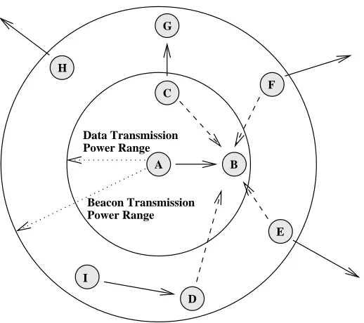
Figure 5.3: Figure shows how nodeAuses a higher beacon transmission power to block out potential interfering nodes for receiver B. C is a one-hop node whose transmission to G
would interfere with both A’s transmission and B’s reception. F andE are two-hop nodes whose transmission would affect B’s reception. I’s transmission to D would not affect A
or B, however D’s acknowledgment to I would interfere with B’s reception. Node H’s transmission would not affectA orB, but it will get blocked out. This is an instance of the exposed terminal due to Siren’s beacon transmission.
receiver [86, 39], as illustrated in Figure 5.3 This problem is not handled in EY-NPMA. To fix this problem, we adopt a higher transmission power for beacon transmissions compared to data transmissions to preserve the correctness of PR across two hops. The transmission power for beacons should be enough to reach all potential interfering nodes for A’s intended receiver. This approach has been used in [50, 71, 98] as well. In our study, we set the beacon transmission power of all nodes to be roughly three times that of their data transmission power for a simplified implementation. This is decided based on the following reasoning. Assuming free-space propagation, where the transmitted signal drops by square root of distance, quadrupling transmission power for beacons corresponds to doubling dis-tance, hence ensuring that the beacon is received by all two-hop interferers. However, since beacon packets need to be only sensed, not received, we find through experiment that simply using three times the data transmission power works for most cases.
conser-vative approach which may cause the beacon transmissions of some nodes to reach farther away from interfering nodes and shut down non-interfering nodes from transmission lead-ing to loss of network capacity. This problem is called the exposed terminal problem. An example is shown in Figure 5.3. Node H will be shut down byA’s beacon, even though its transmission will not interfere withA’s transmission toB. Recent work has established that it is possible to detect the interference relations between nodes on a run-time basis [103]. In addition, transmission power can also be tuned so that transmissions reach only a set of interfering nodes [62]. Hence it is possible to tune the beacon transmission power on a per-node basis, so that it reaches the set of interfering nodes and no farther. This will not eliminate all cases of exposed terminals, but will definitely result in improvement in network capacity. However, we do not explore this option in this thesis, and leave it for future work. Our experimental results presented in Section 5.6 are obtained without this tuning. We use -5 dBm (316µW) transmit power for data packets, and 0 dBm (1 mW) for beacons.
Time Synchronization
Siren does not require global clock synchronization. The protocol works as long as the sender is synchronized with all potential interferers (both one and two-hop nodes). Hence conventional distributed clock synchronization algorithms which depend on hop-by-hop clock synchronization [37, 69] are appropriate for Siren. We use FTSP [69] for our testbed.
We use the FTSP [69] algorithm for time synchronization. 3 In our multi-hop testbed comprising of 30 MicaZ sensor nodes, the FTSP algorithm takes 4 minutes (with time synch messages broadcast every 10 seconds) for all nodes to synchronize. All data transmissions begin 4 minutes after the start of the experiment. Since time synchronization messages are sent as broadcast they are prone to loss due to collisions with data packets. This makes it difficult to maintain time synchronization under high network load. To prevent this problem, synchronization messages are sent with a priority level 0.
3