Multi-Zone Security System for Controlling
the Trespasser
Y.Anusha1, P.V.V.N.D.P.Sunil2, V.Naga Gowthami3, K.Shadrak4 , M.Jhansi Tirumala5, S.Karteek Sai6
4th year Students, Department of Electronics and Communication Engineering, DMS SVH College of Engineering,
AndhraPradesh, India 1,3,4,5,6
Assistant Professor, Department of Electronics and Communication Engineering, DMS SVH College of Engineering,
Andhra Pradesh, India2
ABSTRACT: Safety and security of any living or working place is one of the most primary concerns. The increasing
occurances of trespassing and new ways of burglary have made it crucial to enhance safety as well as security through the use of modern technology. Thus our project aims to develop a low-cost and fast reactive means of building security system. Using array of passive Infrared sensors, this system can reduce the extent of danger that can be caused by the trespasser and alerts the owner or the authorized person of building about the same.
KEYWORDS: RFID; GSM module; ARM CORTEX; Buzzer; IR Sensors, L293D motor driver, DC Motor.
I. INTRODUCTION
Today’s security systems include surveillance cameras which are very costly and many of these systems do not trigger any alarm if intrusion is detected. Such systems usually have no mechanism to send critical information to users/authorized persons if any intruder enters into their office/home premises and cannot control him from entering into that area. Thus a low cost and fast-reactive security system is needed to be developed. The system presented in this paper aims to improve upon such shortcomings of other security systems.
Hence this system detects the trespasser using IR Sensors, gives out alarm to indicate that the person has entered into restricted area, sends alert message to authorized person and controls the trespasser from entering into the restricted area.
II. LITERATURE SURVEY
The present day security systems are suffering with the issue of security levels. The less number of security levels can be easily faked by robbers [1]. Such systems may offer some merits in the form of low cost and relative ease of installation but they also present some major drawbacks. Such systems usually have no mechanism to send critical information to users/home owners if they are not present in the home premises [2]. This security system is based on embedded system along with GSM and sensor networks. The human movement is detected using the IR sensors. In this time, the system triggers an alarm detecting the presence of person [3]. The introduced system operation is supported by a GSM Embedded mobile module, which enables the alert messages transmission to both mobile devices of end users, and security offices [4].
III. IMPLEMENTATION/KEY FEATURES
By using a number of IR sensor pairs and microcontroller that are described in the following sections, this system is able to incorporate some crucial features into its functioning.
This system uses Infrared radiation sensors placed in such a way to form three zones around the building to monitor the presence of trespassers and possible intruders near the homes entry around the building. This enables the system to react only when the trespasser enters.
This system uses buzzer to give out alarm initially when any person enters into this area.
Fig 1. System response when trespasser enters first zone
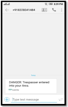
This system uses GSM module to immediately inform the owner or authorized person when the trespasser enters into this restricted area.
Fig 2. System response when trespasser enters second zone
This system should perform the shooting of chemical compounds when it perceives danger. But in this system
we have demonstrated it by activating the DC motor.
Fig 3. System response when trespasser crosses the third zone
This system uses the RFID module to know whether the person entering is authorized or not by verifying their
RFID tag.
There is also an integrated deactivating mechanism in this system placed along the gate way to allow the authorized members when they want to enter into this area.
The IR sensors are interfaced to the ARM CORTEX M4 which processes their outputs. The ARM CORTEX
IV. PROPOSED SYSTEM
A. Block diagram
Fig 4. Block diagram overview of the system Fig 5. Picture of system
Fig. 5 clearly explains the idea of proposed system. The main component is the ARM Cortex TM4C123GH6PM and all the sensors are given as the inputs to the processor. Depending on outputs received data, the processed data will give out alarm, sends alert message to authorized person using GSM module and activates the DC motor. Now the clear description of the components in the system is given below clearly.
B. ARM Cortex M4
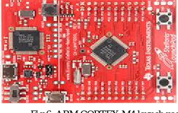
Fig 6. ARM CORTEX M4 launch pad
ARM CORTEX TM4C123GH6PM is a microcontroller launch pad. It is a 32 bit processer having 80MHz operating frequency, on chip memory of 256KB flash, 32KB RAM, 2KB EEROM, USB, 8 UART’s, 4 I2C SPI,12 bit ADC. It contains everything needed to support the microcontroller; simply connect it to a computer through a USB cable or supply power to it through adapter or battery to get started [5].
C. IR Sensors
An infrared sensor is an electronic instrument which is used to sense certain characteristics of its surroundings by either emitting and/or detecting infrared radiation. Everlights Infrared emitting diode IR533C is a high intensity diode wounded with a water clear plastic package. This is spectrally matched with phototransistor, photodiode and infrared receiver module. Infrared sensors are electronic devices which are used to measure the heat being emitted by an object
and detecting motion. The infrared waves typically have wavelengths between 0.75m and 1000µm. Passive IR sensors
Fig 7: IR LED and photodiode
D. RFID Tag
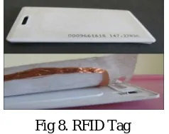
RFID tag is a small microchip designed for wireless data transmission. It is generally attached to an Antenna in a package that resembles an ordinary adhesive sticker. An RFID tag transmits data over the air in response to interrogation by an RFID reader. The data transmitted by the tag provides identification of the person. Below figure gives the inside view of the tag [7].
Fig 8. RFID Tag
For this system either passive tag or active tag can be used depending on the requirement and distance at which RFID is placed.
Fig 9. RFID Reader and Tag
The above figure shows how RFID reader and tag can ex-change the information.
E. RFID Reader
There are three types of RFID readers based on their frequency ranges, low frequency, high frequency and ultra-high frequency. The reader emits radio waves depending upon its power output and radio frequency used. When an RFID tag passes through the Electromagnetic zone, it detects the reader’s activation signal. The reader decodes the data encoded in the tags integrated circuit (silicon chip) and the data is passed to the microcontroller for processing. The EM-18 is a low frequency (125 KHz) RFID reader with serial output with at range of 8-12cm. It is a compact unit with built in antenna. It is an inexpensive solution for this RFID based application. The Reader module contains a microchip and an antenna and can be powered up with a 5V power supply [8].
G. GSM (Global System for Mobile Communications)
GSM was developed by the European Telecommunications Standards Institute (ETSI) which de-scribes the
protocols for 2G cellular networks used in mobile phones. It can communicate with microcontrollers by using various
900MHz or 1800MHz. As the GSM operators allow the users to use their same mobile phone in different countries by changing the SIM card [4].
Fig 10: GSM module
H. DC Motor
DC motor converts electrical power into mechanical power. It works on the Principle: "whenever a current carrying conductor is placed in a magnetic field, it experiences a mechanical force".
I. L293D Motor driver
L293D is a dual H-bridge motor driver integrated circuit. Motor driver take a low-current control signal and provide a higher-current signal, thus they act as current amplifiers. This higher current signal is used to drive the motors.
L293D contains two inbuilt H-bridge driver circuits. These two DC motors can be driven simultaneously, either in forward or reverse direction [9].
Fig 11. Motor driver l293D IC
J. Buzzer
A buzzer or beeper is an audio signaling device.
K. Energia
V. HARDWARE IMPLEMENTATION
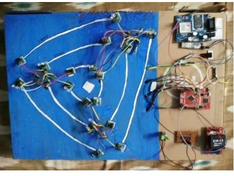
The below figure shows clearly the assembling of all the components.
Fig 12: Hardware connections
Here the 9 pairs of IR Sensors, RFID Reader, Buzzer, GSM Module and L293D Motor driver are interfaced with the ARM CORTEX Launch pad. The motor driver output pins are connected to the DC Motor. The analog outputs of all the IR pairs are continuously sends to the ARM CORTEX. The outputs of these are converted into digital value in it. Depending on the output value the ARM CORTEX process the further action. When an RFID tag passes through the Electromagnetic zone, the reader detects and decodes the data in tag and sends it to the microcontroller for processing.
VI. RESULTS
The results that are obtained when a trespasser starts entering into the building crossing the zones. When the trespasser starts crossing the first zone, then the output value of sensors changes as results of which the ARM cortex enables the buzzer to give out alarm.
Fig 13: Message sent using GSM module
When the trespasser is crossing the third zone, the output value of sensors changes as result of which the ARM cortex activates the DC motor indicating that shooting of chemical compounds into the trespasser takes place.
If any Authorized person wants to enter into the building, their RFID tag is brought into the EM field of RFID reader, then the data in tag is compared with RFID reader memory and if matches (green led glows), gate way IR sensors will be in off state allowing the Authorized person to enter through gate way and if it does match (red led glows) the system will be working as usually.
VII. CONCLUSION AND FUTURE WORK
This paper presents a security system to detect the trespasser using the IR sensors. It gives out alarm when trespasser initially enters into the restricted area using the Buzzer, Alerts the authorized person that a trespasser has entered into their area using the GSM module and Controls the trespasser from entering into the restricted area. It verifies whether the person with RFID tag is Authorized person decides whether to allow him or not. Thus cost effective and fast reactive security system is developed.
Further, the system in this paper can be easily expanded to include various additional features, functionalities and services. For example, the deactivation mechanism could be replaced from the current RFID tag to Iris scanning or even a voice-command based activation/deactivation of certain part of this security system.
REFERENCES
[1]”A Multi Layer Bank Security System”, Green computing, communication and conservation of Energy (ICGCE), 2013 International conference. [2]Manish Kumar, Shubham Kaul, “Technical Report on Intruder Detection and Alert System”, CII Innovation, 2015.
[3] M.Sathish kumar, S.Rajini, “ Smart Surveillance System Using PIR Sensor Network and GSM, International Journal of Advanced Research in Computer Engineering and Technology(IJARCET), volume 4, issue 1, January 2015.
[4]Eleni Isa, Nicolas Sklavos, “Smart Home Automation: GSM Security System Design and Implementation”, IEEE conference paper, May 2015. [5]” TM4C123GH6PM-ARM Cortex launch pad”, available at:-http://www.ti.com/product/TM4C123GH6PM
[6]”IR533C-Everlight infrared LED”, available at:-http://www.fairchip.com/everlight/infrared-products/emitter/21918-IR533C-Everlight-infrared-LED.html
[7]K.Varsha, Jyoti choudhary, Madhuri kodgi, M.S.Indira, “Barcode and RFID based Security System, International Journal of Engineering Innovation & Research, volume 4, issue 2, ISSN:2277-5668,2015.
[8]”EM-18 RFID reader”, available at:-http://www.nskelectronics.com/em-18_rfid_reader.html